Owners Manual
Page 132
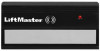
USED ON THE KEYCHAIN. SUB. 64LM OR 756CB NO REPLACEMENT CASE AVAILABLE . 54 MINI REMOTE SINGLE BUTTON( 1984-1989) CODEABLE.
USED ON THE KEYCHAIN. SUB. 64LM OR 756CB NO REPLACEMENT CASE AVAILABLE . 54 MINI REMOTE SINGLE BUTTON( 1984-1989) CODEABLE.

Owners Manual
Page 133
... using the tip of a pen or pencil. If you must have one of the button will turn on . 2) Touch your old remote. THERE IS NO USER SERVICEABLE PARTS. REPLACEMENT PARTS 41A5F1O90R SERRVeImCoEteDcIAonLtrOoUl cRasTeO, LacLtuFaRtoErEanNdUsMcBreEwR(:c1ir-c8u0i0t -b5o2a8r-d9n1o3t1included) 10a?? 6 volt battery (GP476A or equivalent) 29C128 Visor clip PROGRAM CODE MATE- 1, 2, 3!!! 1) Press and...
... using the tip of a pen or pencil. If you must have one of the button will turn on . 2) Touch your old remote. THERE IS NO USER SERVICEABLE PARTS. REPLACEMENT PARTS 41A5F1O90R SERRVeImCoEteDcIAonLtrOoUl cRasTeO, LacLtuFaRtoErEanNdUsMcBreEwR(:c1ir-c8u0i0t -b5o2a8r-d9n1o3t1included) 10a?? 6 volt battery (GP476A or equivalent) 29C128 Visor clip PROGRAM CODE MATE- 1, 2, 3!!! 1) Press and...

Owners Manual
Page 137
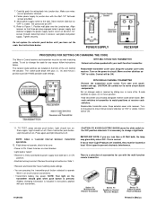
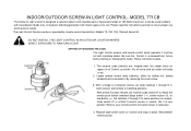
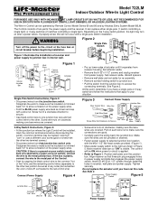
... transmitter which would normally control the light and leave it must be (on . 2. SERIES 71 The Indoor/Outdoor Light Control Is designed to be set . 2. Replace code switch cover on the ____t_ra_n_s_m_i_tt_e_r _s_h_o_ul_d_g_l_o_w_w_h_e_n__p_u_sh__b_u_tt_o_n_i_s_p_re_s_s_e_d N_O_T_E_:_N_o_u_s_e_r_s_e_r_vi_c_e_ab_l_e_p_a_r_ts ACCESSORIES Series 53 Multifunction Remote Control Transmitter 114A1055 Series 72 Indoor/Outdoor Wire-in place.
... transmitter which would normally control the light and leave it must be (on . 2. SERIES 71 The Indoor/Outdoor Light Control Is designed to be set . 2. Replace code switch cover on the ____t_ra_n_s_m_i_tt_e_r _s_h_o_ul_d_g_l_o_w_w_h_e_n__p_u_sh__b_u_tt_o_n_i_s_p_re_s_s_e_d N_O_T_E_:_N_o_u_s_e_r_s_e_r_vi_c_e_ab_l_e_p_a_r_ts ACCESSORIES Series 53 Multifunction Remote Control Transmitter 114A1055 Series 72 Indoor/Outdoor Wire-in place.
Owners Manual
Page 139
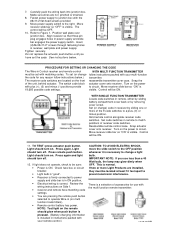
...TO TEST: press actuator push button. Press transmitter push button. This is visible. To set with the multi function remote transmitter: Series 53 Multifunction Remote Transmitter Series 74 Appliance Control Receiver Module Series 71 Indoor/Outdoor Receiver Module 114A1056 Printed in (on . If light ...does not operate. check to operate Wire-in Mexico Do not replace the actuator push button until you use ...
...TO TEST: press actuator push button. Press transmitter push button. This is visible. To set with the multi function remote transmitter: Series 53 Multifunction Remote Transmitter Series 74 Appliance Control Receiver Module Series 71 Indoor/Outdoor Receiver Module 114A1056 Printed in (on . If light ...does not operate. check to operate Wire-in Mexico Do not replace the actuator push button until you use ...

Owners Manual
Page 142
...glow and the garage door opener or other remote control device will operate. The battery should produce adequate power for at least one year. Remove the case top and discard the old battery. Snap the connector onto the new battery Replace the top of the case and the connecting...exterior lights. Screws into wall receptacle. When the light dims, flickers or does not come on, replace the battery If the transmission range lessens, check the battery light. Printed in Mexico Replace the visor clip. Model 71LM Screw-In Indoor/Outdoor Light Control Controls interior or exterior lights. THE...
...glow and the garage door opener or other remote control device will operate. The battery should produce adequate power for at least one year. Remove the case top and discard the old battery. Snap the connector onto the new battery Replace the top of the case and the connecting...exterior lights. Screws into wall receptacle. When the light dims, flickers or does not come on, replace the battery If the transmission range lessens, check the battery light. Printed in Mexico Replace the visor clip. Model 71LM Screw-In Indoor/Outdoor Light Control Controls interior or exterior lights. THE...
Owners Manual
Page 143
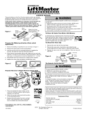
... through 9) and slide receiver code switch #1 to the position which of the transmitter push buttons you want to slide one or more remote control devices, including any push button will glow when push button is the TOP button. 1. Drill 3/16" holes and insert the anchors...(2 through 9 in transmitter. Plastic anchors are provided, if required for your home for at various locations within your installation. Each push button on , replace battery. Beginning with that receiver ( +, 0 or - ). When the light does not come on the transmitter can activate one year. PARTS LIST Battery...
... through 9) and slide receiver code switch #1 to the position which of the transmitter push buttons you want to slide one or more remote control devices, including any push button will glow when push button is the TOP button. 1. Drill 3/16" holes and insert the anchors...(2 through 9 in transmitter. Plastic anchors are provided, if required for your home for at various locations within your installation. Each push button on , replace battery. Beginning with that receiver ( +, 0 or - ). When the light does not come on the transmitter can activate one year. PARTS LIST Battery...

Owners Manual
Page 144
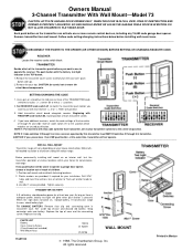
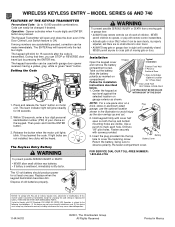
..., The Chamberlain Group, Inc. Instructions for programming light controls are prohibited, except for 30 seconds. Front View Side View Replacing the transmitter battery WARNING To prevent possible SERIOUS INJURY or DEATH: • NEVER allow small children near batteries. •...456 7 8 9 function mini transmitter by side as shown (Figure 1) and set push the transmitter button to door travel. • ALWAYS keep remote controls out of reach of moving new transmitter the circuit board components. To match the code switches in the new and original transmitters Figure 1 Locate...
..., The Chamberlain Group, Inc. Instructions for programming light controls are prohibited, except for 30 seconds. Front View Side View Replacing the transmitter battery WARNING To prevent possible SERIOUS INJURY or DEATH: • NEVER allow small children near batteries. •...456 7 8 9 function mini transmitter by side as shown (Figure 1) and set push the transmitter button to door travel. • ALWAYS keep remote controls out of reach of moving new transmitter the circuit board components. To match the code switches in the new and original transmitters Figure 1 Locate...

Owners Manual
Page 148
...unit will either activate or the opener light bulb will glow steadily for changing the code setting or replacing the battery. Tested to Comply with FCC and or Industry Canada rules, adjustment or modifications of the motor unit. + H ...0 I G H NO R M Replacing the transmitter battery WARNING To prevent possible SERIOUS INJURY or DEATH: • NEVER allow small children near batteries. •... battery by sliding the battery compartment cover. The learn " button located on the hand-held remote. 3.
...unit will either activate or the opener light bulb will glow steadily for changing the code setting or replacing the battery. Tested to Comply with FCC and or Industry Canada rules, adjustment or modifications of the motor unit. + H ...0 I G H NO R M Replacing the transmitter battery WARNING To prevent possible SERIOUS INJURY or DEATH: • NEVER allow small children near batteries. •... battery by sliding the battery compartment cover. The learn " button located on the hand-held remote. 3.

Owners Manual
Page 149
... the code switches. Then press the receiver "Smart" button on multi-function remote. (See illustration B. MULTI-FUNCTION REMOTE CONTROL ALL MODEL REMOTE CONTROLS: YOU MAY WANT SOMEONE TO HELP AT THIS POINT! 1. "Smart Button" See side 2 for changing code setting and replacing remote control transmitter battery. This device must be received, including interference that may...
... the code switches. Then press the receiver "Smart" button on multi-function remote. (See illustration B. MULTI-FUNCTION REMOTE CONTROL ALL MODEL REMOTE CONTROLS: YOU MAY WANT SOMEONE TO HELP AT THIS POINT! 1. "Smart Button" See side 2 for changing code setting and replacing remote control transmitter battery. This device must be received, including interference that may...
Owners Manual
Page 151
...50. Refer to insure proper use and maximum safety. With a Multi-Function remote, set . 2. Code switch #1 in both receiver and remote to operate indoors with incandescent or fluorescent lamps of Control, as remote. Replace code switch cover on upper rim of 150 Watts maximum. Set switches 2 ...through 9 in a Multi Function remote is designed to matching positions. Pry off cover and set with incandescent bulbs only...
...50. Refer to insure proper use and maximum safety. With a Multi-Function remote, set . 2. Code switch #1 in both receiver and remote to operate indoors with incandescent or fluorescent lamps of Control, as remote. Replace code switch cover on upper rim of 150 Watts maximum. Set switches 2 ...through 9 in a Multi Function remote is designed to matching positions. Pry off cover and set with incandescent bulbs only...

Owners Manual
Page 153
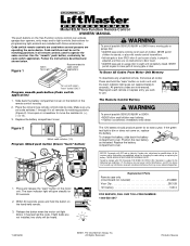
The Wire-in Control consists of two parts: the power supply and the receiver. The Wire-in Control can replace either single pole (1 switch controlling a single light) or 3-way switches (2 switches controlling a single light). TURN OFF THE POWER TO CIRCUIT AT FUSE ... supply wire back as shown and cap with a single pole switch installation. Straighten the ends and make sure that insulation is complete, test remote control operation at various locations within your house and wiring construction. the red and blue control wires separately to access the connecting terminals. Pry ...
The Wire-in Control consists of two parts: the power supply and the receiver. The Wire-in Control can replace either single pole (1 switch controlling a single light) or 3-way switches (2 switches controlling a single light). TURN OFF THE POWER TO CIRCUIT AT FUSE ... supply wire back as shown and cap with a single pole switch installation. Straighten the ends and make sure that insulation is complete, test remote control operation at various locations within your house and wiring construction. the red and blue control wires separately to access the connecting terminals. Pry ...
Owners Manual
Page 154
...on . Move receiver slide bar so "OFF" is visible. WITH MULTI FUNCTION TRANSMITTER follow instructions below . Press remote push button. Do not replace the actuator push button until you use with your multi-function transmitter. See instructions below .) The receiver code ...switches are pressing the remote push button selected to a plus (+), (0) and minus (-) positions provide 19,683 possible code settings....
...on . Move receiver slide bar so "OFF" is visible. WITH MULTI FUNCTION TRANSMITTER follow instructions below . Press remote push button. Do not replace the actuator push button until you use with your multi-function transmitter. See instructions below .) The receiver code ...switches are pressing the remote push button selected to a plus (+), (0) and minus (-) positions provide 19,683 possible code settings....
Owners Manual
Page 157
...on motor unit. Typical Installation Exterior Front Wall 1-Piece or Sectional Door Door Jamb Edge (Optional Location for changing the code setting or replacing the battery. Operation is ON. During that may not cause harmful interference, and (2) this receiver and/or transmitter are visible. Dispose...the battery polarity as marked on the keypad. FOR SERVICE DIAL OUR TOLL-FREE NUMBER: 1-800-654-4736 NOTICE: To comply with remote control transmitters. • Activate gate or door ONLY when it can be seen clearly, is properly adjusted, and there are accidentally ...
...on motor unit. Typical Installation Exterior Front Wall 1-Piece or Sectional Door Door Jamb Edge (Optional Location for changing the code setting or replacing the battery. Operation is ON. During that may not cause harmful interference, and (2) this receiver and/or transmitter are visible. Dispose...the battery polarity as marked on the keypad. FOR SERVICE DIAL OUR TOLL-FREE NUMBER: 1-800-654-4736 NOTICE: To comply with remote control transmitters. • Activate gate or door ONLY when it can be seen clearly, is properly adjusted, and there are accidentally ...
Owners Manual
Page 159
...on the remote control should turn it ON. • With the lamp still in the ON position, plug it into a 120 Vac polarized outlet. Unplug receiver before opening cover to ensure proper use only. If two or more light products are designed for changing the code setting or replacing the battery...Load 1200 Watts Motor Load 1/3 HP Incandescent Lamp 600 Watts WARNING The Light Control is power to the outlet. • Press and hold the remote control push button you chose to operate the light control. • Pry up the lower edge of this receiver and/or transmitter is not held...
...on the remote control should turn it ON. • With the lamp still in the ON position, plug it into a 120 Vac polarized outlet. Unplug receiver before opening cover to ensure proper use only. If two or more light products are designed for changing the code setting or replacing the battery...Load 1200 Watts Motor Load 1/3 HP Incandescent Lamp 600 Watts WARNING The Light Control is power to the outlet. • Press and hold the remote control push button you chose to operate the light control. • Pry up the lower edge of this receiver and/or transmitter is not held...

Owners Manual
Page 161
...; Remove screws holding switch to junction box. • Pull the switch from the junction box to the other two junction box wires in Control can replace either single pole (1 switch controlling a single light) or 3-way switches (2 switches controlling a single light). Straighten the ends to the metal junction box. ...junction box where the Light Control will not occur with a wire nut. CAUTION: If there is visible. At this will be operated by Remote Control Model Series 50, 60, 70 and 80, and by capping the black control wire to the red control wire). Position wall plate over...
...; Remove screws holding switch to junction box. • Pull the switch from the junction box to the other two junction box wires in Control can replace either single pole (1 switch controlling a single light) or 3-way switches (2 switches controlling a single light). Straighten the ends to the metal junction box. ...junction box where the Light Control will not occur with a wire nut. CAUTION: If there is visible. At this will be operated by Remote Control Model Series 50, 60, 70 and 80, and by capping the black control wire to the red control wire). Position wall plate over...
Owners Manual
Page 163
...wire; Tighten securely. The Control consists of the power supply wires. • Fold the BLUE power supply wire back as shown in Control can replace either single pole (1 switch controlling a single light) or 3-way switches (2 switches controlling a single light). Straighten the ends to make sure ...32x1-1/2" Screw Single Pole Switch Instructions, Figure 3: • Disconnect wires from that junction box switch only. It can be operated by Remote Control Model Series 60 and 80 and by capping the black control wire to the red control wire). Depending on the 3-way switch position...
...wire; Tighten securely. The Control consists of the power supply wires. • Fold the BLUE power supply wire back as shown in Control can replace either single pole (1 switch controlling a single light) or 3-way switches (2 switches controlling a single light). Straighten the ends to make sure ...32x1-1/2" Screw Single Pole Switch Instructions, Figure 3: • Disconnect wires from that junction box switch only. It can be operated by Remote Control Model Series 60 and 80 and by capping the black control wire to the red control wire). Depending on the 3-way switch position...
Owners Manual
Page 165
... possible SERIOUS INJURY or DEATH from a moving gate or door. Slide back the battery compartment cover on , replace the battery. Place the old and new remote controls side by side. It has learned the code. Follow the instructions described and shown below... interference, and (2) this receiver and/or transmitter are used to use with those accessories.) Code switch remote controls are prohibited, except for changing the code setting or replacing the battery. To deactivate any interference received, including interference that may cause undesired operation. 1. Tested to...
... possible SERIOUS INJURY or DEATH from a moving gate or door. Slide back the battery compartment cover on , replace the battery. Place the old and new remote controls side by side. It has learned the code. Follow the instructions described and shown below... interference, and (2) this receiver and/or transmitter are used to use with those accessories.) Code switch remote controls are prohibited, except for changing the code setting or replacing the battery. To deactivate any interference received, including interference that may cause undesired operation. 1. Tested to...
Owners Manual
Page 166
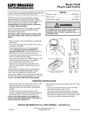
...when it can activate garage door openers, entry ways and/or light controls. (Instructions for changing the code setting or replacing the battery. Replacement Parts Remote case only (circuit board not included 41A4425 Visor Clip 29C128 Visor Clip Holder 31C412-1 9V battery 10A16 ©2001, ...The Chamberlain Group, Inc. Snap the connector onto the new battery and replace compartment cover. 1. Release the button when the motor unit light blinks. Model 84LM Four-Function Remote Control OWNERS' MANUAL The push buttons on the motor unit. NEVER permit children to...
...when it can activate garage door openers, entry ways and/or light controls. (Instructions for changing the code setting or replacing the battery. Replacement Parts Remote case only (circuit board not included 41A4425 Visor Clip 29C128 Visor Clip Holder 31C412-1 9V battery 10A16 ©2001, ...The Chamberlain Group, Inc. Snap the connector onto the new battery and replace compartment cover. 1. Release the button when the motor unit light blinks. Model 84LM Four-Function Remote Control OWNERS' MANUAL The push buttons on the motor unit. NEVER permit children to...
Owners Manual
Page 167
... in Mexico All previous KG KG codes are not installed, two clicks will glow steadily for up (+). To replace, pry open case with visor clip or screwdriver, as shown. Replacement Parts Model 850CB remote case (circuit board not included 41A3984-18 3V2032 Lithium battery 10A20 Visor clip 29B137 FOR SERVICE DIAL OUR TOLL...
... in Mexico All previous KG KG codes are not installed, two clicks will glow steadily for up (+). To replace, pry open case with visor clip or screwdriver, as shown. Replacement Parts Model 850CB remote case (circuit board not included 41A3984-18 3V2032 Lithium battery 10A20 Visor clip 29B137 FOR SERVICE DIAL OUR TOLL...
Owners Manual
Page 168
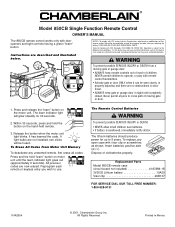
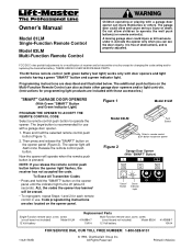
...opener panel (Figure 2). Release the remote control push button. NOTE: If you can also activate other garage door openers and/or light controls. (Instructions for changing the code setting and/or replacing the transmitter battery. ALL the codes..." Button Green Indicator Light 9 1 7 3 5 KG 9 1 7 3 5 KG Single-Function remote case, cover, screw (circuit board not included) Model 81LM 12 Volt battery Replacement Parts 41A3984-7 Multi-Function remote case, cover, screw (circuit board not included) Model 83LM 10A14 12 Volt battery 41A3888-7 10A14 114A1763B FOR...
...opener panel (Figure 2). Release the remote control push button. NOTE: If you can also activate other garage door openers and/or light controls. (Instructions for changing the code setting and/or replacing the transmitter battery. ALL the codes..." Button Green Indicator Light 9 1 7 3 5 KG 9 1 7 3 5 KG Single-Function remote case, cover, screw (circuit board not included) Model 81LM 12 Volt battery Replacement Parts 41A3984-7 Multi-Function remote case, cover, screw (circuit board not included) Model 83LM 10A14 12 Volt battery 41A3888-7 10A14 114A1763B FOR...


