
APT LOGIC 3 Manual
Page 1
... Alert System LED. Radio Receiver Built on the 3-button station will signal when the set an internal Maintenance Cycle Counter. L 3 ogic OWNER'S MANUAL APT INDUSTRIAL DUTY COMMERCIAL DOOR OPERATOR This Operator Features the Enhanced INTENAN MA E M E C AL 2 YEAR WARRANTY Serial # Box Installation Date E PATENT PENDING R T T SYS The Maintenance Alert System™ allows the...
... Alert System LED. Radio Receiver Built on the 3-button station will signal when the set an internal Maintenance Cycle Counter. L 3 ogic OWNER'S MANUAL APT INDUSTRIAL DUTY COMMERCIAL DOOR OPERATOR This Operator Features the Enhanced INTENAN MA E M E C AL 2 YEAR WARRANTY Serial # Box Installation Date E PATENT PENDING R T T SYS The Maintenance Alert System™ allows the...

APT LOGIC 3 Manual
Page 2
... Guide 26 Troubleshooting Error Codes 27 Troubleshooting Radio Functionality 28 REPAIR PARTS Electrical Box 30-31 Repair Parts Kits 32-33 Operator Notes 34-35 Control Connection Diagram 36 WARNING Mechanical WCAARUNTIIONNG Electrical CWAAURTNIOINNG WARNING IMPORTANT NOTES: WWAARRNNIINNGG • BEFORE attempting to... Safety Symbols and Signal Words on the following pages, they will alert you to the possibility of damage to install, operate or maintain the operator, you must read and fully understand this manual and follow all safety instructions. • DO NOT attempt repair or ...
... Guide 26 Troubleshooting Error Codes 27 Troubleshooting Radio Functionality 28 REPAIR PARTS Electrical Box 30-31 Repair Parts Kits 32-33 Operator Notes 34-35 Control Connection Diagram 36 WARNING Mechanical WCAARUNTIIONNG Electrical CWAAURTNIOINNG WARNING IMPORTANT NOTES: WWAARRNNIINNGG • BEFORE attempting to... Safety Symbols and Signal Words on the following pages, they will alert you to the possibility of damage to install, operate or maintain the operator, you must read and fully understand this manual and follow all safety instructions. • DO NOT attempt repair or ...

APT LOGIC 3 Manual
Page 3
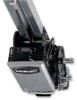
CARTON INVENTORY Before beginning your installation check that all components were provided. OPERATOR DIMENSIONS WEIGHTS AND DIMENSIONS HANGING WEIGHT: 80-110 LBS. (36.3-50 kg) 4" (104.2" cm) 131.035-1"/8(3"3.15 cm) * Do*DoroHoreHigehitgPhltuPslu4sfe4efte(emti(n1im.2u2mm)) (minimum) Highest ...
CARTON INVENTORY Before beginning your installation check that all components were provided. OPERATOR DIMENSIONS WEIGHTS AND DIMENSIONS HANGING WEIGHT: 80-110 LBS. (36.3-50 kg) 4" (104.2" cm) 131.035-1"/8(3"3.15 cm) * Do*DoroHoreHigehitgPhltuPslu4sfe4efte(emti(n1im.2u2mm)) (minimum) Highest ...
APT LOGIC 3 Manual
Page 4
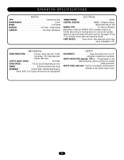
... Through beam or retro reflective devices used to open and close with open override. Output: #48 chain OUTPUT SHAFT SPEED 96 R.P.M. OPERATOR SPECIFICATIONS MOTOR TYPE Continuous Duty HORSEPOWER 1/2 HP SPEED 1725 RPM VOLTAGE 115 Volts - See pages 16 and 17 for emergency manual door... operation. Secondary: #41 chain/sprocket. DOOR SPEED 7-8" per second depending on door BRAKE Solenoid actuated disc brake BEARINGS Output Shaft: Shielded Ball Bearing...
... Through beam or retro reflective devices used to open and close with open override. Output: #48 chain OUTPUT SHAFT SPEED 96 R.P.M. OPERATOR SPECIFICATIONS MOTOR TYPE Continuous Duty HORSEPOWER 1/2 HP SPEED 1725 RPM VOLTAGE 115 Volts - See pages 16 and 17 for emergency manual door... operation. Secondary: #41 chain/sprocket. DOOR SPEED 7-8" per second depending on door BRAKE Solenoid actuated disc brake BEARINGS Output Shaft: Shielded Ball Bearing...

APT LOGIC 3 Manual
Page 5
...of the chain and determine where to the second set of holes of one end of the track. POWERHEAD ATTACHMENT 1. Refer to the operator by installing and tightening the track spacer brackets. Tie the release cord to the powerhead. Position the spacers evenly over the length of ... extreme tension and can cause SERIOUS PERSONAL INJURY. • Disable ALL locks and remove ALL ropes connected to door BEFORE installing and operating door operator to assure that the hole of track. Slide the trolley carriage back and forth past the drive link to avoid entanglement. Slide the...
...of the chain and determine where to the second set of holes of one end of the track. POWERHEAD ATTACHMENT 1. Refer to the operator by installing and tightening the track spacer brackets. Tie the release cord to the powerhead. Position the spacers evenly over the length of ... extreme tension and can cause SERIOUS PERSONAL INJURY. • Disable ALL locks and remove ALL ropes connected to door BEFORE installing and operating door operator to assure that the hole of track. Slide the trolley carriage back and forth past the drive link to avoid entanglement. Slide the...
APT LOGIC 3 Manual
Page 6
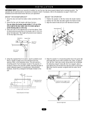
...75" (4.5 cm) Guide Rails 4" Min. (10.2 cm) High Rise Point Projection Line Using the door as shown. Make sure that suit your application. The operator may be sure the door has been properly aligned and is horizontal. Align the bracket holes and join with a suitable rope, chain, or support from... as shown. MOUNT THE HEADER BRACKET 1. You can fasten the header bracket within 2' (.61 m) of the left or right of the operator. Open your operator is in the way. 3. Draw an intersecting horizontal line on page 5. Extend the line onto the header wall above the high point. ...
...75" (4.5 cm) Guide Rails 4" Min. (10.2 cm) High Rise Point Projection Line Using the door as shown. Make sure that suit your application. The operator may be sure the door has been properly aligned and is horizontal. Align the bracket holes and join with a suitable rope, chain, or support from... as shown. MOUNT THE HEADER BRACKET 1. You can fasten the header bracket within 2' (.61 m) of the left or right of the operator. Open your operator is in the way. 3. Draw an intersecting horizontal line on page 5. Extend the line onto the header wall above the high point. ...

APT LOGIC 3 Manual
Page 7
...will be used for the door. Refer to the illustration below shows a typical method of hanging the operator from a falling operator, CAUTION fasten it SECURELY to the powerhead. I N S TA L L AT I O N HANG THE OPERATOR 1. For mounting of a mid-span support is longer than 15' (4.57 m) use of the ...the ceiling. Attach straight door arm to the door. Each installation may vary, but in the trolley carriage. 3. NOTE: If the operator is recommended. Using suitable hardware, attach the door bracket to the fixed roll pin in all bolts and lag screws are located on ...
...will be used for the door. Refer to the illustration below shows a typical method of hanging the operator from a falling operator, CAUTION fasten it SECURELY to the powerhead. I N S TA L L AT I O N HANG THE OPERATOR 1. For mounting of a mid-span support is longer than 15' (4.57 m) use of the ...the ceiling. Attach straight door arm to the door. Each installation may vary, but in the trolley carriage. 3. NOTE: If the operator is recommended. Using suitable hardware, attach the door bracket to the fixed roll pin in all bolts and lag screws are located on ...

APT LOGIC 3 Manual
Page 8
...limit switches before making any sensing edge wiring connections to order or receive more information on safety devices, please contact your operator. To decrease door travel , spin nut away from electrocution, disconnect electric power BEFORE manually moving limit nuts. SAFETY (...I N S TA L L AT I O N ENTRAPMENT PROTECTION ACCESSORIES (OPTIONAL) PHOTO EYES & SENSING EDGES Sensing devices provided for door industry type operators with an isolated normally open (N.O.) dry contact output are compatible with top of door opening . This includes pneumatic and electric edges, and through beam ...
...limit switches before making any sensing edge wiring connections to order or receive more information on safety devices, please contact your operator. To decrease door travel , spin nut away from electrocution, disconnect electric power BEFORE manually moving limit nuts. SAFETY (...I N S TA L L AT I O N ENTRAPMENT PROTECTION ACCESSORIES (OPTIONAL) PHOTO EYES & SENSING EDGES Sensing devices provided for door industry type operators with an isolated normally open (N.O.) dry contact output are compatible with top of door opening . This includes pneumatic and electric edges, and through beam ...
APT LOGIC 3 Manual
Page 9
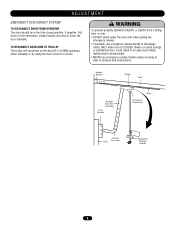
Pull down on the next UP or DOWN operation, either manually or by using the door control or remote. Weak or broken springs or unbalanced door could result in the fully closed position, if ... arm when pulling the emergency release. • If possible, use emergency release handle unless doorway is CLOSED. ADJUSTMENT EMERGENCY DISCONNECT SYSTEM TO DISCONNECT DOOR FROM OPERATOR The door should be in an open door falling rapidly and/or unexpectedly. • NEVER use emergency release handle to disengage trolley ONLY when door...
Pull down on the next UP or DOWN operation, either manually or by using the door control or remote. Weak or broken springs or unbalanced door could result in the fully closed position, if ... arm when pulling the emergency release. • If possible, use emergency release handle unless doorway is CLOSED. ADJUSTMENT EMERGENCY DISCONNECT SYSTEM TO DISCONNECT DOOR FROM OPERATOR The door should be in an open door falling rapidly and/or unexpectedly. • NEVER use emergency release handle to disengage trolley ONLY when door...

APT LOGIC 3 Manual
Page 10
ADJUSTMENT BRAKE ADJUSTMENT The solenoid brake is adjusted at the factory and should generally be possible to protect the door and motorized operator. Replace brake assembly when necessary. Remove cotterpin from nut on the clutch spring. 3. Back off clutch nut until there is obstructed. ... obstruction. The Auxiliary Reversal System works in tandem with the adjustable clutch to slip if the door is just enough tension to permit the operator to move the door smoothly but to allow the clutch to detect if a closing or stops the door when opening. 1. Tighten clutch ...
ADJUSTMENT BRAKE ADJUSTMENT The solenoid brake is adjusted at the factory and should generally be possible to protect the door and motorized operator. Replace brake assembly when necessary. Remove cotterpin from nut on the clutch spring. 3. Back off clutch nut until there is obstructed. ... obstruction. The Auxiliary Reversal System works in tandem with the adjustable clutch to slip if the door is just enough tension to permit the operator to move the door smoothly but to allow the clutch to detect if a closing or stops the door when opening. 1. Tighten clutch ...

APT LOGIC 3 Manual
Page 11
... the power wiring. IMPORTANT NOTE: This unit must be performed until disconnecting the electrical power and locking-out the power via the operator power switch. We recommend that time the unit may be properly grounded. Connect power wires coming from the main to the captive ...block in electric shock and serious injury. The location of the power disconnect should be properly grounded and connected in the electrical box enclosure. 2. Operator MUST be on a separate fused line of adequate capacity. • ALL electrical connections MUST be made by a qualified individual. • DO...
... the power wiring. IMPORTANT NOTE: This unit must be performed until disconnecting the electrical power and locking-out the power via the operator power switch. We recommend that time the unit may be properly grounded. Connect power wires coming from the main to the captive ...block in electric shock and serious injury. The location of the power disconnect should be properly grounded and connected in the electrical box enclosure. 2. Operator MUST be on a separate fused line of adequate capacity. • ALL electrical connections MUST be made by a qualified individual. • DO...

APT LOGIC 3 Manual
Page 12
... 24 VOLT AC 24V AC 13 24 VOLT AC TIMER DEFEAT 12 TIMER DEFEAT CMN 11 COMMON MAS 10 MAINTENANCE ALERT SYSTEM EYES 9 PHOTO EYES (LiftMaster Only) EDGE 8 REVERSE OPEN 7 OPEN CLOSE 6 CLOSE STOP 5 STOP CMN 4 COMMON 3 INTERLOCK 2 INTERLOCK SBC 1 SINGLE BUTTON CONTROL MOUNTING INSTRUCTIONS 1. UPON ... STOP button. Connect control wires to close limit location. Then relocate the safety limit switch (SLS) only to the operator. OR IN THE AREA NEAR THE OPERATOR MUST NOT BE PERFORMED UNTIL DISCONNECTING THE ELECTRICAL POWER AND LOCKING-OUT THE POWER VIA, THE MAIN DISCONNECT SWITCH. In ...
... 24 VOLT AC 24V AC 13 24 VOLT AC TIMER DEFEAT 12 TIMER DEFEAT CMN 11 COMMON MAS 10 MAINTENANCE ALERT SYSTEM EYES 9 PHOTO EYES (LiftMaster Only) EDGE 8 REVERSE OPEN 7 OPEN CLOSE 6 CLOSE STOP 5 STOP CMN 4 COMMON 3 INTERLOCK 2 INTERLOCK SBC 1 SINGLE BUTTON CONTROL MOUNTING INSTRUCTIONS 1. UPON ... STOP button. Connect control wires to close limit location. Then relocate the safety limit switch (SLS) only to the operator. OR IN THE AREA NEAR THE OPERATOR MUST NOT BE PERFORMED UNTIL DISCONNECTING THE ELECTRICAL POWER AND LOCKING-OUT THE POWER VIA, THE MAIN DISCONNECT SWITCH. In ...
APT LOGIC 3 Manual
Page 16
.... NOTE: Refer to logic board illustration on board push buttons to assist setting the limits. Programmable mid stop control or a jumper must also set the operators open and close with 3-Button Station, 1-Button Station and 1 & 3 Button Remote Control. Release of the different wiring types to determine which setting will be wired...
.... NOTE: Refer to logic board illustration on board push buttons to assist setting the limits. Programmable mid stop control or a jumper must also set the operators open and close with 3-Button Station, 1-Button Station and 1 & 3 Button Remote Control. Release of the different wiring types to determine which setting will be wired...
APT LOGIC 3 Manual
Page 17
... Compatible with 3-Button Station, 1-Button Station, 1 & 3 Button Remote Control. (NOTE: Requires Optional self monitoring photo eyes to operate this wiring type. If the timer has been activated, the open button and radio control can recycle the timer. Compatible with open ... or CPS3 card with 3-Button Station, 1-Button Station and 1 & 3 Button Remote Control. (NOTE: Requires Optional self monitoring photo eyes to operate.) T Momentary contact to open, close and stop. Compatible with 3-Button Station and 3-Button Remote. E2 Failsafe Same functions as B2. The stop...
... Compatible with 3-Button Station, 1-Button Station, 1 & 3 Button Remote Control. (NOTE: Requires Optional self monitoring photo eyes to operate this wiring type. If the timer has been activated, the open button and radio control can recycle the timer. Compatible with open ... or CPS3 card with 3-Button Station, 1-Button Station and 1 & 3 Button Remote Control. (NOTE: Requires Optional self monitoring photo eyes to operate.) T Momentary contact to open, close and stop. Compatible with 3-Button Station and 3-Button Remote. E2 Failsafe Same functions as B2. The stop...

APT LOGIC 3 Manual
Page 18
...programming mode is exited if no activity is performed within 30 seconds. PROGRAMMING REMOTES STANDARD SINGLE BUTTON REMOTE 1. The programming mode is exited if no operation in D1 mode. SINGLE BUTTON CONTROL (SBC) REMOTE This function programs a remote as 23 Security✚® remotes or dip switch remote controls.... on the logic board (LED will then remain on solid after releasing. 4. NOTICE: To comply with D1 and E2 failsafe wiring modes. RADIO LiftMaster P4 E1 R29 C11 D3Ø2 K3 Ø14LGØ65 X1 C54 U1 C71 C78 ® OLS D25 REV MID D24 SLS D26 ...
...programming mode is exited if no activity is performed within 30 seconds. PROGRAMMING REMOTES STANDARD SINGLE BUTTON REMOTE 1. The programming mode is exited if no operation in D1 mode. SINGLE BUTTON CONTROL (SBC) REMOTE This function programs a remote as 23 Security✚® remotes or dip switch remote controls.... on the logic board (LED will then remain on solid after releasing. 4. NOTICE: To comply with D1 and E2 failsafe wiring modes. RADIO LiftMaster P4 E1 R29 C11 D3Ø2 K3 Ø14LGØ65 X1 C54 U1 C71 C78 ® OLS D25 REV MID D24 SLS D26 ...

APT LOGIC 3 Manual
Page 19
... open the door, the middle button will close the door, and the third button will automatically exit programming mode. To program the OPEN button to operate as follows: 1.
... open the door, the middle button will close the door, and the third button will automatically exit programming mode. To program the OPEN button to operate as follows: 1.
APT LOGIC 3 Manual
Page 20
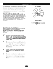
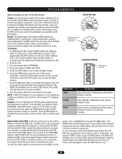
...STATION OPEN Maintenance Alert LED CLOSE STOP Press This OPEN CLOSE STOP To Get This Adds 5,000 cycles to reset the MAS with the operator. Press the STOP button once to complete the programming. NOTE: If MAS LED flashes 2 or more flashes in setting up a routine.... Example: A door is optional. Benefit: The Maintenance Alert System (MAS) assists the installing dealer in a row followed by a pause, an operator error occurred. The Maintenance Alert System (MAS) assists the installing dealer in the PROGRAM mode to Maintenance Alert System Activation Counter. Turn the selector dial...
...STATION OPEN Maintenance Alert LED CLOSE STOP Press This OPEN CLOSE STOP To Get This Adds 5,000 cycles to reset the MAS with the operator. Press the STOP button once to complete the programming. NOTE: If MAS LED flashes 2 or more flashes in setting up a routine.... Example: A door is optional. Benefit: The Maintenance Alert System (MAS) assists the installing dealer in a row followed by a pause, an operator error occurred. The Maintenance Alert System (MAS) assists the installing dealer in the PROGRAM mode to Maintenance Alert System Activation Counter. Turn the selector dial...
APT LOGIC 3 Manual
Page 21
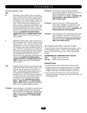
... the desired mid stop feature is used. Once at least one of how to close after a specified amount of time. SELECTOR DIAL Operation will automatically close automatically after pre set the selector dial to close the door. See kit instructions of the following safety devices attached: CPS...sensors when the 3-button control station is the down mid stop position, except in E2 mode. Press the CLOSE button for every 5 seconds the operator should wait before attempting to Program and press and hold the MID SET button for 5 seconds. Press the TIMER button to "PROGRAM." 3. ...
... the desired mid stop feature is used. Once at least one of how to close after a specified amount of time. SELECTOR DIAL Operation will automatically close automatically after pre set the selector dial to close the door. See kit instructions of the following safety devices attached: CPS...sensors when the 3-button control station is the down mid stop position, except in E2 mode. Press the CLOSE button for every 5 seconds the operator should wait before attempting to Program and press and hold the MID SET button for 5 seconds. Press the TIMER button to "PROGRAM." 3. ...

APT LOGIC 3 Manual
Page 22
...door (clutch must be reactivated on models GH and GT.) NOTE: This feature is automatically learned and does not require programming. SELECTOR DIAL Operation will turn on.) 7. PROGRAMMING TIMER TO CLOSE PROGRAM TIMER TO CLOSE BY EXAMPLE (Method 2): To Program: 1. NOTES: To read ...1/3 and 1/2 horsepower single phase motors, the leading cause of motor failures is eliminated. (Auxiliary Reversal System not applicable on the next operation command. Close the door 2. Press and hold TIMER button for primary safety protection. Wait for desired amount of safety devices for 5 seconds...
...door (clutch must be reactivated on models GH and GT.) NOTE: This feature is automatically learned and does not require programming. SELECTOR DIAL Operation will turn on.) 7. PROGRAMMING TIMER TO CLOSE PROGRAM TIMER TO CLOSE BY EXAMPLE (Method 2): To Program: 1. NOTES: To read ...1/3 and 1/2 horsepower single phase motors, the leading cause of motor failures is eliminated. (Auxiliary Reversal System not applicable on the next operation command. Close the door 2. Press and hold TIMER button for primary safety protection. Wait for desired amount of safety devices for 5 seconds...

APT LOGIC 3 Manual
Page 23
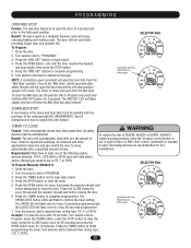
... program and press and hold the MRT button until close and until the MAS led flashes rapidly. Turn dial to "PROGRAM." 3. SELECTOR DIAL Operation will receive power as indicated at least one of the door closing helps prevent traffic collisions with the door in the closed position. 2. To ... activated Greater than 10 seconds 10 seconds before reaching the mid stop or the open position, programming is 90 seconds. Light Control Module Operation: The green lights on the OPTION BOARD will turn selector dial to close limit is on if the board is seated properly and the...
... program and press and hold the MRT button until close and until the MAS led flashes rapidly. Turn dial to "PROGRAM." 3. SELECTOR DIAL Operation will receive power as indicated at least one of the door closing helps prevent traffic collisions with the door in the closed position. 2. To ... activated Greater than 10 seconds 10 seconds before reaching the mid stop or the open position, programming is 90 seconds. Light Control Module Operation: The green lights on the OPTION BOARD will turn selector dial to close limit is on if the board is seated properly and the...


