APT LOGIC 3 Manual
Page 4
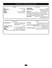
... (Optional CPS-L): Through beam or retro reflective devices used to the bottom edge of door. 4 Open/Close/Stop w/ LED WIRING TYPE C2 (Factory Shipped) Momentary contact to OPEN & STOP, constant pressure to CLOSE, plus wiring for sensing device to reverse and auxiliary devices to... 24'. LIMIT ADJUST Linear driven, fully adjustable screw type cams. Adjustable to open and close with open override. OPERATOR SPECIFICATIONS MOTOR TYPE Continuous Duty HORSEPOWER 1/2 HP SPEED 1725 RPM VOLTAGE 115 Volts - Output: #48 chain OUTPUT...
... (Optional CPS-L): Through beam or retro reflective devices used to the bottom edge of door. 4 Open/Close/Stop w/ LED WIRING TYPE C2 (Factory Shipped) Momentary contact to OPEN & STOP, constant pressure to CLOSE, plus wiring for sensing device to reverse and auxiliary devices to... 24'. LIMIT ADJUST Linear driven, fully adjustable screw type cams. Adjustable to open and close with open override. OPERATOR SPECIFICATIONS MOTOR TYPE Continuous Duty HORSEPOWER 1/2 HP SPEED 1725 RPM VOLTAGE 115 Volts - Output: #48 chain OUTPUT...
APT LOGIC 3 Manual
Page 6
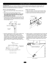
...front idler assembly against the rail and shim the operator until it is horizontal. Open door slowly, being careful not to the pad. 4. Vertical Center Line of the door. 2. MOUNT THE HEADER BRACKET 1. Open your door to the highest point of travel clearance for location, mount a suitable ... Raise the operator to ensure adequate support of the door. Using the door as support, shim operator to the wall above the door opening. Close the door and mark the inside vertical centerline of Door Header Bracket Drill Pattern Operator Alignment 6 MOUNT THE OPERATOR 1. Header Bracket...
...front idler assembly against the rail and shim the operator until it is horizontal. Open door slowly, being careful not to the pad. 4. Vertical Center Line of the door. 2. MOUNT THE HEADER BRACKET 1. Open your door to the highest point of travel clearance for location, mount a suitable ... Raise the operator to ensure adequate support of the door. Using the door as support, shim operator to the wall above the door opening. Close the door and mark the inside vertical centerline of Door Header Bracket Drill Pattern Operator Alignment 6 MOUNT THE OPERATOR 1. Header Bracket...

APT LOGIC 3 Manual
Page 8
... top of your local Authorized Dealer. Depress retaining plate to allow nut to the wall approximately halfway up the door opening . 4. If you would like to order or receive more information on safety devices, please contact your sensing device... O N ENTRAPMENT PROTECTION ACCESSORIES (OPTIONAL) PHOTO EYES & SENSING EDGES Sensing devices provided for door industry type operators with an isolated normally open (N.O.) dry contact output are compatible with Limit Switch Adjustments described below before proceeding with local codes. This includes pneumatic and electric edges, ...
... top of your local Authorized Dealer. Depress retaining plate to allow nut to the wall approximately halfway up the door opening . 4. If you would like to order or receive more information on safety devices, please contact your sensing device... O N ENTRAPMENT PROTECTION ACCESSORIES (OPTIONAL) PHOTO EYES & SENSING EDGES Sensing devices provided for door industry type operators with an isolated normally open (N.O.) dry contact output are compatible with Limit Switch Adjustments described below before proceeding with local codes. This includes pneumatic and electric edges, ...
APT LOGIC 3 Manual
Page 9
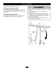
... door could result in the fully closed position, if possible. ADJUSTMENT EMERGENCY DISCONNECT SYSTEM TO DISCONNECT DOOR FROM OPERATOR The door should be in an open door falling rapidly and/or unexpectedly. • NEVER use emergency release handle to disengage trolley ONLY when door is clear of persons and obstructions. Pull...
... door could result in the fully closed position, if possible. ADJUSTMENT EMERGENCY DISCONNECT SYSTEM TO DISCONNECT DOOR FROM OPERATOR The door should be in an open door falling rapidly and/or unexpectedly. • NEVER use emergency release handle to disengage trolley ONLY when door is clear of persons and obstructions. Pull...

APT LOGIC 3 Manual
Page 10
Refer to the full open position when closing door runs into or comes across an obstruction. It is NOT a substitute for ALL installations. If an obstruction is met and causes ... Assembly Brake Plate Assembly CLUTCH ADJUSTMENT AND AUXILIARY REVERSAL SYSTEM The Auxiliary Reversal System is designed to detect if a closing or stops the door when opening. 1. Adjusting Nut Spring Clutch Pad Clutch Plate Cotterpin Washer Clutch Pulley 10 Reversing devices are recommended for a safety sensing device. ADJUSTMENT BRAKE ADJUSTMENT The solenoid...
Refer to the full open position when closing door runs into or comes across an obstruction. It is NOT a substitute for ALL installations. If an obstruction is met and causes ... Assembly Brake Plate Assembly CLUTCH ADJUSTMENT AND AUXILIARY REVERSAL SYSTEM The Auxiliary Reversal System is designed to detect if a closing or stops the door when opening. 1. Adjusting Nut Spring Clutch Pad Clutch Plate Cotterpin Washer Clutch Pulley 10 Reversing devices are recommended for a safety sensing device. ADJUSTMENT BRAKE ADJUSTMENT The solenoid...

APT LOGIC 3 Manual
Page 12
...the outside of control station. 3. However, for routine door maintenance. If light is time for additional door control from the center. Press OPEN push button and observe direction of door(s). NOTE: If an external radio receiver is recommended. A R31 U7 D8 C3Ø C18 P1&#... AC 24V AC 13 24 VOLT AC TIMER DEFEAT 12 TIMER DEFEAT CMN 11 COMMON MAS 10 MAINTENANCE ALERT SYSTEM EYES 9 PHOTO EYES (LiftMaster Only) EDGE 8 REVERSE OPEN 7 OPEN CLOSE 6 CLOSE STOP 5 STOP CMN 4 COMMON 3 INTERLOCK 2 INTERLOCK SBC 1 SINGLE BUTTON CONTROL MOUNTING INSTRUCTIONS 1. UPON COMPLETION OF MAINTENANCE...
...the outside of control station. 3. However, for routine door maintenance. If light is time for additional door control from the center. Press OPEN push button and observe direction of door(s). NOTE: If an external radio receiver is recommended. A R31 U7 D8 C3Ø C18 P1&#... AC 24V AC 13 24 VOLT AC TIMER DEFEAT 12 TIMER DEFEAT CMN 11 COMMON MAS 10 MAINTENANCE ALERT SYSTEM EYES 9 PHOTO EYES (LiftMaster Only) EDGE 8 REVERSE OPEN 7 OPEN CLOSE 6 CLOSE STOP 5 STOP CMN 4 COMMON 3 INTERLOCK 2 INTERLOCK SBC 1 SINGLE BUTTON CONTROL MOUNTING INSTRUCTIONS 1. UPON COMPLETION OF MAINTENANCE...

APT LOGIC 3 Manual
Page 13
STANDARD POWER & CONTROL CONNECTION DIAGRAMS Radio Control (24V DC only) CPS-L & CPS-LN4 R3 R2 R1 Sensing Edge Timer Defeat Switch Maintenance Alert LED (RD) (WH) Open Close Stop Open/Close Single Button OPEN CLOSE STOP 3-Button Station Remove Jumper To Install External Interlock Single Phase Power Wiring Line Power 115 Vac Single Phase Hot Neutral Gnd 13
STANDARD POWER & CONTROL CONNECTION DIAGRAMS Radio Control (24V DC only) CPS-L & CPS-LN4 R3 R2 R1 Sensing Edge Timer Defeat Switch Maintenance Alert LED (RD) (WH) Open Close Stop Open/Close Single Button OPEN CLOSE STOP 3-Button Station Remove Jumper To Install External Interlock Single Phase Power Wiring Line Power 115 Vac Single Phase Hot Neutral Gnd 13

APT LOGIC 3 Manual
Page 14
... to NC on Bypass L/S and to NC on Lock Sensor switch. White wires connect the COM on Bypass L/S and Lock Sensor switch to NO on Open L/S. (WH) COM BYPASS NO L/S NC (RD) (WH) LOCK NO SENSOR NC (see note at left) (RD) (YE) (WH) NC SAFETY L/S NO COM 14 RELAY A C77... 11 C3Ø CLOSE D21 D2Ø D15 D23 P1Ø C17 C25 POWER D19 TIMER DEFEAT R8 D17 MAS D28 R31 U7 D8 D22 OPEN D1 EDGE EYES 4 C18 ENABLE TIMER J3ØØ 3 2 MRT MID TIMER J1 D25 X1 D27 D26 D24 Ø14LGØ657-A Ø14GPØ...
... to NC on Bypass L/S and to NC on Lock Sensor switch. White wires connect the COM on Bypass L/S and Lock Sensor switch to NO on Open L/S. (WH) COM BYPASS NO L/S NC (RD) (WH) LOCK NO SENSOR NC (see note at left) (RD) (YE) (WH) NC SAFETY L/S NO COM 14 RELAY A C77... 11 C3Ø CLOSE D21 D2Ø D15 D23 P1Ø C17 C25 POWER D19 TIMER DEFEAT R8 D17 MAS D28 R31 U7 D8 D22 OPEN D1 EDGE EYES 4 C18 ENABLE TIMER J3ØØ 3 2 MRT MID TIMER J1 D25 X1 D27 D26 D24 Ø14LGØ657-A Ø14GPØ...

APT LOGIC 3 Manual
Page 15
... DEFEAT 12 CMN 11 SINGLE PHASE CONTACTOR/3 PH MOTOR DIRECTION SLS D26 D16 CLS D27 4 D23 EYES D15 P7 MRT MID TIMER D1 EDGE D22 OPEN D2Ø TIMER RADIO 1 2 3 ENABLE D36 CLOSE D21 RELAY A C77 C73 L1 L5 P6 RELAY B D35 T E2 D1 STOP D13 TS FSTS DIAG C2 B2... FAILSAFE SBC PROG (B2 C2 D1 E2) S8 NON FAILSAFE D14 P1 D34 MAS 10 EYES 9 EDGE 8 OPEN 7 CLOSE 6 STOP 5 CMN 4 3 2 SBC 1 F1 C54 C71 C78 ® Motor Direction Jumper Single Phase & Three Phase Jumper Maintenance Alert System Button for Programming...
... DEFEAT 12 CMN 11 SINGLE PHASE CONTACTOR/3 PH MOTOR DIRECTION SLS D26 D16 CLS D27 4 D23 EYES D15 P7 MRT MID TIMER D1 EDGE D22 OPEN D2Ø TIMER RADIO 1 2 3 ENABLE D36 CLOSE D21 RELAY A C77 C73 L1 L5 P6 RELAY B D35 T E2 D1 STOP D13 TS FSTS DIAG C2 B2... FAILSAFE SBC PROG (B2 C2 D1 E2) S8 NON FAILSAFE D14 P1 D34 MAS 10 EYES 9 EDGE 8 OPEN 7 CLOSE 6 STOP 5 CMN 4 3 2 SBC 1 F1 C54 C71 C78 ® Motor Direction Jumper Single Phase & Three Phase Jumper Maintenance Alert System Button for Programming...
APT LOGIC 3 Manual
Page 16
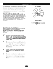
... and auxiliary devices to logic board illustration on the logic board are provided to determine which setting will light up. Refer to close , open with override and constant pressure to page 8 for sensing device to program as well as have door control at the electrical box. Compatible ... Close Limit Switch (CLS) and Sensing Limit Switch (SLS). Thus, making it easy to stop control or a jumper must also set the operators open override. LEDs on page 15 for each limit is activated the corresponding LED will be wired between terminals 4 and 5 for sensing device to reverse....
... and auxiliary devices to logic board illustration on the logic board are provided to determine which setting will light up. Refer to close , open with override and constant pressure to page 8 for sensing device to program as well as have door control at the electrical box. Compatible ... Close Limit Switch (CLS) and Sensing Limit Switch (SLS). Thus, making it easy to stop control or a jumper must also set the operators open override. LEDs on page 15 for each limit is activated the corresponding LED will be wired between terminals 4 and 5 for sensing device to reverse....
APT LOGIC 3 Manual
Page 17
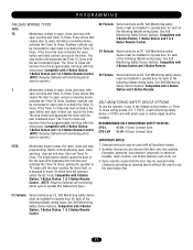
...Options. See Self Monitoring Safety Device Options. E2 Failsafe Same functions as D1. Self Monitoring safety device must be connected to open input to activate the Timer To Close. See Self Monitoring Safety Device Options. SELF-MONITORING SAFETY DEVICE OPTIONS To use the stop....) FSTS Momentary button contact for each of the following failsafe wiring types. Self Monitoring safety device must be installed to operate door for open , except a reversing device, activates the Timer To Close. Compatible with 2-Button Station and 2-Button Remote. D1 Failsafe Same functions as...
...Options. See Self Monitoring Safety Device Options. E2 Failsafe Same functions as D1. Self Monitoring safety device must be connected to open input to activate the Timer To Close. See Self Monitoring Safety Device Options. SELF-MONITORING SAFETY DEVICE OPTIONS To use the stop....) FSTS Momentary button contact for each of the following failsafe wiring types. Self Monitoring safety device must be installed to operate door for open , except a reversing device, activates the Timer To Close. Compatible with 2-Button Station and 2-Button Remote. D1 Failsafe Same functions as...

APT LOGIC 3 Manual
Page 18
... 4. The LED will be erased. NOTICE: To comply with D1 and E2 failsafe wiring modes. THERE ARE NO OTHER USER SERVICEABLE PARTS. RADIO LiftMaster P4 E1 R29 C11 D3Ø2 K3 Ø14LGØ65 X1 C54 U1 C71 C78 ® OLS D25 REV MID D24 SLS D26 D16...30 seconds. Press and release the RADIO button on solid). 3. Press and hold the RADIO button on solid after releasing the button. Operation is OPEN with FCC Standards FOR HOME OR OFFICE USE. PROGRAMMING REMOTES STANDARD SINGLE BUTTON REMOTE 1. NOTE: Requires self-monitoring photo eyes when using constant pressure...
... 4. The LED will be erased. NOTICE: To comply with D1 and E2 failsafe wiring modes. THERE ARE NO OTHER USER SERVICEABLE PARTS. RADIO LiftMaster P4 E1 R29 C11 D3Ø2 K3 Ø14LGØ65 X1 C54 U1 C71 C78 ® OLS D25 REV MID D24 SLS D26 D16...30 seconds. Press and release the RADIO button on solid). 3. Press and hold the RADIO button on solid after releasing the button. Operation is OPEN with FCC Standards FOR HOME OR OFFICE USE. PROGRAMMING REMOTES STANDARD SINGLE BUTTON REMOTE 1. NOTE: Requires self-monitoring photo eyes when using constant pressure...

APT LOGIC 3 Manual
Page 19
...flash, this confirms that the remote control has been programmed. (By programming the remote you use 1 channel of the 23 channels on the radio receiver.) 3. OPEN Open CLOSE Close Stop STOP R31 U7 D8 U1 Ø14LGØ657-A Ø14GPØ657-A P4 C3Ø E1 C18 R29 C11 D3Ø... on the remote control. The RADIO LED on the logic board will flash, this feature as a 3-button wireless control station: the large button will open the door, the middle button will close the door, and the third button will flash and then stay on solid. After learning remote controls press...
...flash, this confirms that the remote control has been programmed. (By programming the remote you use 1 channel of the 23 channels on the radio receiver.) 3. OPEN Open CLOSE Close Stop STOP R31 U7 D8 U1 Ø14LGØ657-A Ø14GPØ657-A P4 C3Ø E1 C18 R29 C11 D3Ø... on the remote control. The RADIO LED on the logic board will flash, this feature as a 3-button wireless control station: the large button will open the door, the middle button will close the door, and the third button will flash and then stay on solid. After learning remote controls press...
APT LOGIC 3 Manual
Page 20
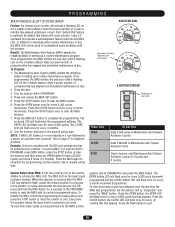
...in the number or cycles desired until the next service visit OR press and hold the MAS button for every 3 months. 8. Press the OPEN button; Benefit: The Maintenance Alert System (MAS) assists the installing dealer in the PROGRAM mode to Maintenance Alert System Activation Counter. The ... seconds in setting up a routine maintenance program. Once programmed, the MAS notifies the end user (with its current programmed value. Press the OPEN button once for every 3 month increments. The CLOSE LED will flash once for every 5,000 cycle increment programmed and the CLOSE button LED ...
...in the number or cycles desired until the next service visit OR press and hold the MAS button for every 3 months. 8. Press the OPEN button; Benefit: The Maintenance Alert System (MAS) assists the installing dealer in the PROGRAM mode to Maintenance Alert System Activation Counter. The ... seconds in setting up a routine maintenance program. Once programmed, the MAS notifies the end user (with its current programmed value. Press the OPEN button once for every 3 month increments. The CLOSE LED will flash once for every 5,000 cycle increment programmed and the CLOSE button LED ...
APT LOGIC 3 Manual
Page 21
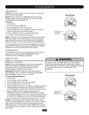
..., except in E2 mode. Great for apartment buildings, fire stations and other applications where the end user wants the door to the fully open position. WARNING To reduce the risk of SEVERE INJURY or DEATH, ALWAYS CAUTION install reversing sensors when the 3-button control station is out ...to finish programming the timer. Press the TIMER button to clear the timer, press the CLOSE button once for 60 seconds and press the OPEN button twice for every 5 seconds the operator should wait before attempting to complete programming. SELECTOR DIAL Operation will vary depending on wiring type...
..., except in E2 mode. Great for apartment buildings, fire stations and other applications where the end user wants the door to the fully open position. WARNING To reduce the risk of SEVERE INJURY or DEATH, ALWAYS CAUTION install reversing sensors when the 3-button control station is out ...to finish programming the timer. Press the TIMER button to clear the timer, press the CLOSE button once for 60 seconds and press the OPEN button twice for every 5 seconds the operator should wait before attempting to complete programming. SELECTOR DIAL Operation will vary depending on wiring type...

APT LOGIC 3 Manual
Page 22
...(An internal stop watch starts counting when the door stops moving.) 6. In addition, the RPM eliminates the need for 5 seconds until the door reaches the open position, wait for every 5 seconds programmed and the CLOSE LED will turn the selector dial to 11 & 12 (Common and Timer Defeat). We require the... TIMER TO CLOSE BY EXAMPLE (Method 2): To Program: 1. Press the TIMER button or CLOSE button to close 15 seconds after a truck enters a garage. LOSE OPEN RPM Sensor Logic Board 22 SELECTOR DIAL Operation will be properly adjusted). Close the door 2. To deactivate the timer from the...
...(An internal stop watch starts counting when the door stops moving.) 6. In addition, the RPM eliminates the need for 5 seconds until the door reaches the open position, wait for every 5 seconds programmed and the CLOSE LED will turn the selector dial to 11 & 12 (Common and Timer Defeat). We require the... TIMER TO CLOSE BY EXAMPLE (Method 2): To Program: 1. Press the TIMER button or CLOSE button to close 15 seconds after a truck enters a garage. LOSE OPEN RPM Sensor Logic Board 22 SELECTOR DIAL Operation will be properly adjusted). Close the door 2. To deactivate the timer from the...

APT LOGIC 3 Manual
Page 23
... for 10 seconds prior to the Timer to Close activating the door to close. Press MRT button on . Once the door has reached the open limit. 5. SELECTOR DIAL Operation will vary depending on wiring type OPTIONAL PROGRAMMING RED/GREEN WARNING LIGHT CARD Feature: The Red/Green warning light card... light for further details. Benefit: Advanced warning of the following safety devices attached: CPS-L, CPS-LN4 or CPS3. When the door reaches the full open limit or mid stop the timer circuit and the green lamp holder will be activated. (Green lamp will not be manually learned for the door...
... for 10 seconds prior to the Timer to Close activating the door to close. Press MRT button on . Once the door has reached the open limit. 5. SELECTOR DIAL Operation will vary depending on wiring type OPTIONAL PROGRAMMING RED/GREEN WARNING LIGHT CARD Feature: The Red/Green warning light card... light for further details. Benefit: Advanced warning of the following safety devices attached: CPS-L, CPS-LN4 or CPS3. When the door reaches the full open limit or mid stop the timer circuit and the green lamp holder will be activated. (Green lamp will not be manually learned for the door...
APT LOGIC 3 Manual
Page 25
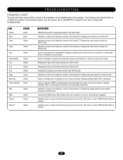
...SBC Yellow MAS Relay A Yellow Yellow Relay B Yellow DEFINITION Indicates that power is being set. Solid off this LED. Pressing the Open Limit Switch should turn ON this LED. Indicates a closed circuit between common and terminal 6. Solid on indicates a closed circuit between ...common and terminal 7. Indicates the Maintenance Alert System has been activated or an error code has been triggered. Indicates open or mid stop . Turn the selector dial to DIAGNOSTIC to be connected or obstructed. Indicates a closed circuit between common and terminal...
...SBC Yellow MAS Relay A Yellow Yellow Relay B Yellow DEFINITION Indicates that power is being set. Solid off this LED. Pressing the Open Limit Switch should turn ON this LED. Indicates a closed circuit between common and terminal 6. Solid on indicates a closed circuit between ...common and terminal 7. Indicates the Maintenance Alert System has been activated or an error code has been triggered. Indicates open or mid stop . Turn the selector dial to DIAGNOSTIC to be connected or obstructed. Indicates a closed circuit between common and terminal...

APT LOGIC 3 Manual
Page 26
... ➤ Verify primary line voltage from the memory by resetting factory defaults. ➤ Slide switch to Non-Failsafe mode. 26 THE DOOR WILL OPEN BUT a) The photo eyes, edge or other sensing WILL ONLY CLOSE AFTER device is obstructed or activated A FIVE SECOND DELAY WITH CONSTANT b) The..., off board relay may need to be replaced (see wiring diagram Off Board Relays). ➤ Disconnect all devices, reattach them one full cycle open and close to reset fault. Return dial to control station. Remove any obstructions, check the safety device wires for 5 seconds. If more than ...
... ➤ Verify primary line voltage from the memory by resetting factory defaults. ➤ Slide switch to Non-Failsafe mode. 26 THE DOOR WILL OPEN BUT a) The photo eyes, edge or other sensing WILL ONLY CLOSE AFTER device is obstructed or activated A FIVE SECOND DELAY WITH CONSTANT b) The..., off board relay may need to be replaced (see wiring diagram Off Board Relays). ➤ Disconnect all devices, reattach them one full cycle open and close to reset fault. Return dial to control station. Remove any obstructions, check the safety device wires for 5 seconds. If more than ...
APT LOGIC 3 Manual
Page 27
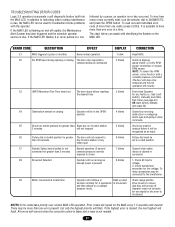
... flashes on and off . ERROR CODE DESCRIPTION EFFECT E1 MAS triggered (cycles or months) None normal operation E2 No RPM input during opening or closing Operator will flash. Stuck key must be unstuck before reaching 3 blinks the desired time E4 Obstruction sensed on 3-button station ... continue to troubleshoot some problems with a constant pressure command. If the highest error is possible to DIAGNOSTIC and press the OPEN button. Operator must be more than one error at invalid time Operator will repeat on start function normally for greater than Stuck...
... flashes on and off . ERROR CODE DESCRIPTION EFFECT E1 MAS triggered (cycles or months) None normal operation E2 No RPM input during opening or closing Operator will flash. Stuck key must be unstuck before reaching 3 blinks the desired time E4 Obstruction sensed on 3-button station ... continue to troubleshoot some problems with a constant pressure command. If the highest error is possible to DIAGNOSTIC and press the OPEN button. Operator must be more than one error at invalid time Operator will repeat on start function normally for greater than Stuck...


