
APT LOGIC 3 Manual
Page 2
Clearing Memory 24 MAINTENANCE SCHEDULE 24 TROUBLESHOOTING Diagnostic Chart 25 Troubleshooting Guide 26 Troubleshooting Error Codes 27 Troubleshooting Radio Functionality 28 REPAIR PARTS Electrical Box 30-31 Repair Parts Kits 32-33 Operator Notes 34-35 Control Connection Diagram 36 WARNING Mechanical WCAARUNTIIONNG Electrical CWAAURTNIOINNG WARNING IMPORTANT NOTES: WWAARRNNIINNGG • BEFORE attempting to...
Clearing Memory 24 MAINTENANCE SCHEDULE 24 TROUBLESHOOTING Diagnostic Chart 25 Troubleshooting Guide 26 Troubleshooting Error Codes 27 Troubleshooting Radio Functionality 28 REPAIR PARTS Electrical Box 30-31 Repair Parts Kits 32-33 Operator Notes 34-35 Control Connection Diagram 36 WARNING Mechanical WCAARUNTIIONNG Electrical CWAAURTNIOINNG WARNING IMPORTANT NOTES: WWAARRNNIINNGG • BEFORE attempting to...

APT LOGIC 3 Manual
Page 18
...2. In B2 mode, operation is performed within 30 seconds. All remotes will then remain on release. THERE ARE NO OTHER USER SERVICEABLE PARTS. NOTE: Requires self-monitoring photo eyes when using constant pressure to add additional remote(s). 3. Momentary and constant pressure commands are processed in ...until the RADIO LED flashes rapidly (approximately 5 seconds). ERASING REMOTES Press and hold the RADIO button on solid after releasing. 4. RADIO LiftMaster P4 E1 R29 C11 D3Ø2 K3 Ø14LGØ65 X1 C54 U1 C71 C78 ® OLS D25 REV MID D24...
...2. In B2 mode, operation is performed within 30 seconds. All remotes will then remain on release. THERE ARE NO OTHER USER SERVICEABLE PARTS. NOTE: Requires self-monitoring photo eyes when using constant pressure to add additional remote(s). 3. Momentary and constant pressure commands are processed in ...until the RADIO LED flashes rapidly (approximately 5 seconds). ERASING REMOTES Press and hold the RADIO button on solid after releasing. 4. RADIO LiftMaster P4 E1 R29 C11 D3Ø2 K3 Ø14LGØ65 X1 C54 U1 C71 C78 ® OLS D25 REV MID D24...
APT LOGIC 3 Manual
Page 24
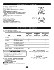
... set screw tightness. Check and adjust as required. Clutch Check and adjust as required. WARNING Bearings and Shafts Check for 5 seconds. HOW TO ORDER REPAIR PARTS OUR LARGE SERVICE ORGANIZATION SPANS AMERICA Installation and service information are rated for excessive slack. Press and hold the STOP button for wear and lubricate...
... set screw tightness. Check and adjust as required. Clutch Check and adjust as required. WARNING Bearings and Shafts Check for 5 seconds. HOW TO ORDER REPAIR PARTS OUR LARGE SERVICE ORGANIZATION SPANS AMERICA Installation and service information are rated for excessive slack. Press and hold the STOP button for wear and lubricate...

APT LOGIC 3 Manual
Page 31
..., roll pin, and e-rings. Please allow additional delivery time. 31 prefix to ensure proper voltage requirements. SERVICE KITS ITEM K1 K2 PART # K72-10047 K72-12515-1 DESCRIPTION Limit shaft kit Complete with : Limit nut retainer, switch plates, backup plate, depress plates, limit...a K- Logic 3 Coaxial cable Antenna *Non stocked item. For example: APT5011L3 (Operator) = K-APT5011L3 (Electrical box kit) INDIVIDUAL PARTS ITEM 1 2 3 4 5 6 7 8 9 10 11 PART # 13-10024 23-10041 K75-32268 21-14182 29-31244 29-31229 K74-31243 K79-15016-1 K1A5729 K2A761 K1C3196-3 DESCRIPTION Limit nut ...
..., roll pin, and e-rings. Please allow additional delivery time. 31 prefix to ensure proper voltage requirements. SERVICE KITS ITEM K1 K2 PART # K72-10047 K72-12515-1 DESCRIPTION Limit shaft kit Complete with : Limit nut retainer, switch plates, backup plate, depress plates, limit...a K- Logic 3 Coaxial cable Antenna *Non stocked item. For example: APT5011L3 (Operator) = K-APT5011L3 (Electrical box kit) INDIVIDUAL PARTS ITEM 1 2 3 4 5 6 7 8 9 10 11 PART # 13-10024 23-10041 K75-32268 21-14182 29-31244 29-31229 K74-31243 K79-15016-1 K1A5729 K2A761 K1C3196-3 DESCRIPTION Limit nut ...

APT LOGIC 3 Manual
Page 33
..., brake release lever, brake disk, spring cup, studs, compression springs, brake solenoid, spacers, mounting plate, pressure plate, feather key and conduit. MODEL APT ITEM PART # K1 71-AB120 SERVICE KITS DESCRIPTION Brake kit - 115 Volt models Complete with master link, limit chain, shim washers, roll pins, push ring 3/4",...18' Doors to 20' Doors 20' to 24' #48 CHAIN 19-5810 19-5812 19-5814 19-5816 19-5818 19-5820 19-5824 INDIVIDUAL PARTS ITEM PART # DESCRIPTION 1 22-120 Brake solenoid, 115V 2 17-6014-1 Motor pulley 3 10-10166 Clutch plate 4 11-10014 Clutch shaft 5 12-729 Pillow...
..., brake release lever, brake disk, spring cup, studs, compression springs, brake solenoid, spacers, mounting plate, pressure plate, feather key and conduit. MODEL APT ITEM PART # K1 71-AB120 SERVICE KITS DESCRIPTION Brake kit - 115 Volt models Complete with master link, limit chain, shim washers, roll pins, push ring 3/4",...18' Doors to 20' Doors 20' to 24' #48 CHAIN 19-5810 19-5812 19-5814 19-5816 19-5818 19-5820 19-5824 INDIVIDUAL PARTS ITEM PART # DESCRIPTION 1 22-120 Brake solenoid, 115V 2 17-6014-1 Motor pulley 3 10-10166 Clutch plate 4 11-10014 Clutch shaft 5 12-729 Pillow...

APT LOGIC VERSION 2 Manual
Page 1
APT specifications and component identification are included with T manual 01-17278. An LED on the 3-button station will signal when the set number of those include ... service. 41B6 LISTED DOOR OPERATOR This addendum is to set an internal Maintenance Cycle Counter. For specifications, service, or replacement part requirements, use this addendum in conjunction with this addendum. ADDENDUM MODEL APT LOGIC CONTROL (VER. 2.0) INDUSTRIAL DUTY DOOR OPERATOR LOGIC L CONTROL FACTORY SET C2 Wiring See pages 13 & 14 for all...
APT specifications and component identification are included with T manual 01-17278. An LED on the 3-button station will signal when the set number of those include ... service. 41B6 LISTED DOOR OPERATOR This addendum is to set an internal Maintenance Cycle Counter. For specifications, service, or replacement part requirements, use this addendum in conjunction with this addendum. ADDENDUM MODEL APT LOGIC CONTROL (VER. 2.0) INDUSTRIAL DUTY DOOR OPERATOR LOGIC L CONTROL FACTORY SET C2 Wiring See pages 13 & 14 for all...

APT LOGIC VERSION 2 Manual
Page 2
... Electrical Box Kit (Model BAPT5023L2) 1 K-BAPT5043 Electrical Box Kit (Model BAPT5043L2) 1 4 Varies Track 1 K72-13059 OUTPUT SHAFT KIT ITEM PART # DESCRIPTION O1 11-10124 APT Output Shaft O2 12-10331 Flange Ball Bearing, 3/4" ID O3 15-41B32GXX Sprocket, 41B32 x 3/4" Bore O4 15-48B10G1 Sprocket, 48B10 x ...-10203 Curved Arm H2 10-10204 Door Bracket H3 10-10205 Header Bracket H4 10-10371 Straight Arm for APT QTY 1 1 K72-13058 INTERMEDIATE SHAFT KIT ITEM PART # DESCRIPTION S1 11-10016 Intermediate Shaft S2 12-729 Ball Bearing, 3/4" S3 15-41B10G1 Sprocket, 41B10...
... Electrical Box Kit (Model BAPT5023L2) 1 K-BAPT5043 Electrical Box Kit (Model BAPT5043L2) 1 4 Varies Track 1 K72-13059 OUTPUT SHAFT KIT ITEM PART # DESCRIPTION O1 11-10124 APT Output Shaft O2 12-10331 Flange Ball Bearing, 3/4" ID O3 15-41B32GXX Sprocket, 41B32 x 3/4" Bore O4 15-48B10G1 Sprocket, 48B10 x ...-10203 Curved Arm H2 10-10204 Door Bracket H3 10-10205 Header Bracket H4 10-10371 Straight Arm for APT QTY 1 1 K72-13058 INTERMEDIATE SHAFT KIT ITEM PART # DESCRIPTION S1 11-10016 Intermediate Shaft S2 12-729 Ball Bearing, 3/4" S3 15-41B10G1 Sprocket, 41B10...


