
APT LOGIC 3 Manual
Page 3
... STATION WITH LED TROLLEY DRIVE CHAIN #48 NOTE: The tracks are shipped separately. CARTON INVENTORY Before beginning your installation check that all components were provided. OPERATOR DIMENSIONS WEIGHTS AND DIMENSIONS HANGING WEIGHT: 80-110 LBS. (36.3-50 kg) 4" (104.2" cm) 131.035-1"/8(3"3.15 cm) * Do*DoroHoreHigehitgPhltuPslu4sfe4efte(emti(n1im.2u2mm)) (minimum) Highest...
... STATION WITH LED TROLLEY DRIVE CHAIN #48 NOTE: The tracks are shipped separately. CARTON INVENTORY Before beginning your installation check that all components were provided. OPERATOR DIMENSIONS WEIGHTS AND DIMENSIONS HANGING WEIGHT: 80-110 LBS. (36.3-50 kg) 4" (104.2" cm) 131.035-1"/8(3"3.15 cm) * Do*DoroHoreHigehitgPhltuPslu4sfe4efte(emti(n1im.2u2mm)) (minimum) Highest...

APT LOGIC 3 Manual
Page 12
... WIRING AND INSTALLATION CONTROL WIRING CONNECTIONS 1. Connect conduit with all models a radio terminal bracket marked R1 R2 R3 is out of ... receiver is being used . Reversing devices are recommended for improper wiring at the control station or between operator and control station. UPON COMPLETION OF MAINTENANCE THE AREA MUST BE CLEARED AND SECURED, AT THAT TIME ...AC 13 24 VOLT AC TIMER DEFEAT 12 TIMER DEFEAT CMN 11 COMMON MAS 10 MAINTENANCE ALERT SYSTEM EYES 9 PHOTO EYES (LiftMaster Only) EDGE 8 REVERSE OPEN 7 OPEN CLOSE 6 CLOSE STOP 5 STOP CMN 4 COMMON 3 INTERLOCK 2 INTERLOCK SBC ...
... WIRING AND INSTALLATION CONTROL WIRING CONNECTIONS 1. Connect conduit with all models a radio terminal bracket marked R1 R2 R3 is out of ... receiver is being used . Reversing devices are recommended for improper wiring at the control station or between operator and control station. UPON COMPLETION OF MAINTENANCE THE AREA MUST BE CLEARED AND SECURED, AT THAT TIME ...AC 13 24 VOLT AC TIMER DEFEAT 12 TIMER DEFEAT CMN 11 COMMON MAS 10 MAINTENANCE ALERT SYSTEM EYES 9 PHOTO EYES (LiftMaster Only) EDGE 8 REVERSE OPEN 7 OPEN CLOSE 6 CLOSE STOP 5 STOP CMN 4 COMMON 3 INTERLOCK 2 INTERLOCK SBC ...

APT LOGIC 3 Manual
Page 22
... to be activated by the Single Button Control (terminal 1) only. Benefit: The Auxiliary Reversal System reverses the operator upon hitting an obstruction, preventing excessive door and operator damage. Press the OPEN button and wait for primary safety protection. Example: The door should close only one cycle... Press the TIMER button or CLOSE button to PROGRAM. 3. Close the door 2. The timer will flash once for a centrifugal switch on models GH and GT.) NOTE: This feature is automatically learned and does not require programming. To program the Timer to Close, turn the selector...
... to be activated by the Single Button Control (terminal 1) only. Benefit: The Auxiliary Reversal System reverses the operator upon hitting an obstruction, preventing excessive door and operator damage. Press the OPEN button and wait for primary safety protection. Example: The door should close only one cycle... Press the TIMER button or CLOSE button to PROGRAM. 3. Close the door 2. The timer will flash once for a centrifugal switch on models GH and GT.) NOTE: This feature is automatically learned and does not require programming. To program the Timer to Close, turn the selector...

APT LOGIC 3 Manual
Page 31
For example: APT5011L3 (Operator) = K-APT5011L3 (Electrical box kit) INDIVIDUAL PARTS ITEM 1 2 3 4 5 6 7 8 9 10 11 PART # 13-10024 23-10041 K75-32268 21-14182 29-31244 29-31229 K74-31243 K79-... voltage requirements. ELECTRICAL BOX LOGIC (VER 3.0) For replacement of electrical box, motor or brake components be sure to match model number of your unit to kit number below to the model number of your operator. Limit switch kit Complete with : Limit shaft, limit nuts, limit bearings, limit sprocket, interrupter cup, shim washers, compression...
For example: APT5011L3 (Operator) = K-APT5011L3 (Electrical box kit) INDIVIDUAL PARTS ITEM 1 2 3 4 5 6 7 8 9 10 11 PART # 13-10024 23-10041 K75-32268 21-14182 29-31244 29-31229 K74-31243 K79-... voltage requirements. ELECTRICAL BOX LOGIC (VER 3.0) For replacement of electrical box, motor or brake components be sure to match model number of your unit to kit number below to the model number of your operator. Limit switch kit Complete with : Limit shaft, limit nuts, limit bearings, limit sprocket, interrupter cup, shim washers, compression...

APT LOGIC VERSION 2 Manual
Page 1
ADDENDUM MODEL APT LOGIC CONTROL (VER. 2.0) INDUSTRIAL DUTY DOOR OPERATOR LOGIC L CONTROL FACTORY SET C2 Wiring See pages 13 & 14 for all mounting and wiring instructions. APT specifications and component identification are included with the manual. For specifications, service, or replacement part requirements, use this .... Refer to be used in lieu of cycles is reached or when the opener requires immediate service. 41B6 LISTED DOOR OPERATOR This addendum is to manual 01-17278 for other wiring configurations PATENT PENDING The Maintenance Alert System TM allows the installer ...
ADDENDUM MODEL APT LOGIC CONTROL (VER. 2.0) INDUSTRIAL DUTY DOOR OPERATOR LOGIC L CONTROL FACTORY SET C2 Wiring See pages 13 & 14 for all mounting and wiring instructions. APT specifications and component identification are included with the manual. For specifications, service, or replacement part requirements, use this .... Refer to be used in lieu of cycles is reached or when the opener requires immediate service. 41B6 LISTED DOOR OPERATOR This addendum is to manual 01-17278 for other wiring configurations PATENT PENDING The Maintenance Alert System TM allows the installer ...
APT LOGIC VERSION 2 Manual
Page 4
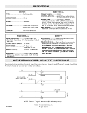
...) IS USED. All rights Reserved MOTOR WIRING DIAGRAM - 115/230 VOLT / SINGLE PHASE See below for optional wiring types and operating modes. See Model T owner's manual for all power and control connections. 01-10384H NOTE: Refer to reverse. OPEN/CLOSE/STOP W/ LED WIRING TYPE...CLOSE, open override plus wiring for sensing device to T logic II Manual for emergency manual door operation. See Model T Manual pages 16, 17 and 18 for internal wiring of motor in Model T owner's manual. Secondary: #41 chain/sprocket. SAFETY DISCONNECT Quick disconnect door arm for O3...
...) IS USED. All rights Reserved MOTOR WIRING DIAGRAM - 115/230 VOLT / SINGLE PHASE See below for optional wiring types and operating modes. See Model T owner's manual for all power and control connections. 01-10384H NOTE: Refer to reverse. OPEN/CLOSE/STOP W/ LED WIRING TYPE...CLOSE, open override plus wiring for sensing device to T logic II Manual for emergency manual door operation. See Model T Manual pages 16, 17 and 18 for internal wiring of motor in Model T owner's manual. Secondary: #41 chain/sprocket. SAFETY DISCONNECT Quick disconnect door arm for O3...


