
"Manufacturer's Certification for Credit" Manual
Page 1
... DC Slide Gate Operator (Model CSL24V) LiftMaster CSL24VDC Commercial High Traffic DC Slide Gate Operator System (Model CSL24VDC) LiftMaster CSW24V Commercial High Traffic DC Swing Gate Operator (Model CSW24V) LiftMaster CSW24VDC Commercial High Traffic DC Swing Gate Operator (Model CSW24VDC) LiftMaster RSL12V Residential DC Slide Gate Operator System (Model RSL12V) LiftMaster RSL12VDC Residential/Light Commercial DC Slide Gate Operator (Model RSL12VDC) LiftMaster RSW12V Residential DC Swing Gate Operator System (Model...
... DC Slide Gate Operator (Model CSL24V) LiftMaster CSL24VDC Commercial High Traffic DC Slide Gate Operator System (Model CSL24VDC) LiftMaster CSW24V Commercial High Traffic DC Swing Gate Operator (Model CSW24V) LiftMaster CSW24VDC Commercial High Traffic DC Swing Gate Operator (Model CSW24VDC) LiftMaster RSL12V Residential DC Slide Gate Operator System (Model RSL12V) LiftMaster RSL12VDC Residential/Light Commercial DC Slide Gate Operator (Model RSL12VDC) LiftMaster RSW12V Residential DC Swing Gate Operator System (Model...
LiftMaster Gate Compatibility Chart Manual
Page 1
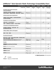
LiftMaster® Gate Operator Radio Technology Compatibility Chart Operator Manufacture Year: Frequency Code: 1993-Present DIP Capable New! 2016 UL 325 Compliant Gate Operators with On-Board Receiver LA400PKGU, LA412PKGU, LA500PKGU • RSL12U, RSW12U CSL24U, CSW24U • CSW200, SL3000 • SL585, SL595 • HCTDCU ✓811LM Tri-Band 1993-1995 Billion Code 390MHz 1996-2005 Security+® Dip...
LiftMaster® Gate Operator Radio Technology Compatibility Chart Operator Manufacture Year: Frequency Code: 1993-Present DIP Capable New! 2016 UL 325 Compliant Gate Operators with On-Board Receiver LA400PKGU, LA412PKGU, LA500PKGU • RSL12U, RSW12U CSL24U, CSW24U • CSW200, SL3000 • SL585, SL595 • HCTDCU ✓811LM Tri-Band 1993-1995 Billion Code 390MHz 1996-2005 Security+® Dip...
LiftMaster Gate Operator Feature Chart Manual
Page 1
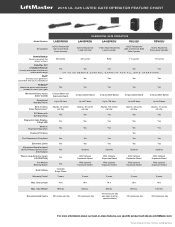
... Motor with Soft Start/Stop Diagnostic Code Display2 Digit LED Wireless Dual-Gate Operation PosiLock® Feature Fire Department Compliant Electronic Limits Expansion Board Included (2) Aux Relays, Quick Close/ Anti-Tailgate Plug-in -class features, see specific product sell sheets at LiftMaster.com *Cycles noted are for specific details) 800 lbs. 120 cycles...
... Motor with Soft Start/Stop Diagnostic Code Display2 Digit LED Wireless Dual-Gate Operation PosiLock® Feature Fire Department Compliant Electronic Limits Expansion Board Included (2) Aux Relays, Quick Close/ Anti-Tailgate Plug-in -class features, see specific product sell sheets at LiftMaster.com *Cycles noted are for specific details) 800 lbs. 120 cycles...

LiftMaster Gate Operator Feature Chart Manual
Page 2
...GATE OPERATORS CSW24U CSL24U HCTDCU ELITE® SERIES AC COMMERCIAL/INDUSTRIAL GATE OPERATORS CSW200 SL3000 SL585 SL595 24VDC High-Traffic Description Commercial Swing Gate Operator 24VDC High-Traffic Commercial Slide Gate Operator 24VDC HighTraffic Overhead Door and Gate Operator AC Commercial High-Traffic Swing Gate Operator AC Commercial High-Traffic Slide Gate Operator AC Industrial Slide Gate Operator AC Heavy-Duty Industrial Slide Gate Operator...per hour © 2015 LiftMaster All Rights Reserved 845 Larch Ave., Elmhurst, IL 60126 LiftMaster.com LMGTCTOOOV 8/15 For more...
...GATE OPERATORS CSW24U CSL24U HCTDCU ELITE® SERIES AC COMMERCIAL/INDUSTRIAL GATE OPERATORS CSW200 SL3000 SL585 SL595 24VDC High-Traffic Description Commercial Swing Gate Operator 24VDC High-Traffic Commercial Slide Gate Operator 24VDC HighTraffic Overhead Door and Gate Operator AC Commercial High-Traffic Swing Gate Operator AC Commercial High-Traffic Slide Gate Operator AC Industrial Slide Gate Operator AC Heavy-Duty Industrial Slide Gate Operator...per hour © 2015 LiftMaster All Rights Reserved 845 Larch Ave., Elmhurst, IL 60126 LiftMaster.com LMGTCTOOOV 8/15 For more...

RSW12U Compact Installation Manual
Page 1
...an obstruction is between 20 to the installation manual for applications where the gate operator arm may look different. LiftMaster 845 Larch Avenue Elmhurst, IL 60126-1196 Your operator may hit an obstruction during movement. Each application is unique and it...total gate system is necessary. • Refer to 32 inches, a compact installation is installed and operated properly. • The images in these instructions are for complete information regarding warnings, installation, testing, and programming. Compact Installation FOR VEHICULAR SWING GATE OPERATORS MODELS CSW24U, ...
...an obstruction is between 20 to the installation manual for applications where the gate operator arm may look different. LiftMaster 845 Larch Avenue Elmhurst, IL 60126-1196 Your operator may hit an obstruction during movement. Each application is unique and it...total gate system is necessary. • Refer to 32 inches, a compact installation is installed and operated properly. • The images in these instructions are for complete information regarding warnings, installation, testing, and programming. Compact Installation FOR VEHICULAR SWING GATE OPERATORS MODELS CSW24U, ...

CSW24U Wiring Diagram Manual
Page 1
... required. Replace APE assembly. 99 Normal Operation No action required COAXIAL CABLE ANTENNA Control Board CONTROLS WIRING DIAGRAM Model CSW24U Jumper N.C. Control Stations OR Photoelectric Sensor ... 7AH J15 Plug Red Black TRANSFORMER Orange -+ -- CODE COLOR KEY: LiftMaster System Installed System Informational External Entrapment Protection Inherent Entrapment Protection CODE MEANING SOLUTION... connections. 34 Absolute Position Encoder Error, not getting position information from other gate operator Shielded Twisted Pair Cable Ground the shield of the cable to the chassis ...
... required. Replace APE assembly. 99 Normal Operation No action required COAXIAL CABLE ANTENNA Control Board CONTROLS WIRING DIAGRAM Model CSW24U Jumper N.C. Control Stations OR Photoelectric Sensor ... 7AH J15 Plug Red Black TRANSFORMER Orange -+ -- CODE COLOR KEY: LiftMaster System Installed System Informational External Entrapment Protection Inherent Entrapment Protection CODE MEANING SOLUTION... connections. 34 Absolute Position Encoder Error, not getting position information from other gate operator Shielded Twisted Pair Cable Ground the shield of the cable to the chassis ...

CSW24U Installation Manual
Page 1
LiftMaster 845 Larch Avenue Elmhurst, IL 60126-1196 Model CSW24U COMMERCIAL DC VEHICULAR SWING GATE OPERATOR INSTALLATION MANUAL • THIS PRODUCT IS TO BE INSTALLED AND SERVICED BY A TRAINED GATE SYSTEMS TECHNICIAN ONLY. • This model is for use on vehicular passage gates ONLY and not intended for use on pedestrian passage gates. • This model is intended...
LiftMaster 845 Larch Avenue Elmhurst, IL 60126-1196 Model CSW24U COMMERCIAL DC VEHICULAR SWING GATE OPERATOR INSTALLATION MANUAL • THIS PRODUCT IS TO BE INSTALLED AND SERVICED BY A TRAINED GATE SYSTEMS TECHNICIAN ONLY. • This model is for use on vehicular passage gates ONLY and not intended for use on pedestrian passage gates. • This model is intended...

CSW24U Installation Manual
Page 3
... 22 ADJUSTMENT 23 LIMIT AND FORCE ADJUSTMENT 23 PROGRAMMING 25 REMOTE CONTROLS (NOT PROVIDED 25 LIFTMASTER INTERNET GATEWAY (NOT PROVIDED 26 ERASE ALL CODES 26 ERASE LIMITS 26 TO REMOVE AND ERASE MONITORED ENTRAPMENT PROTECTION DEVICES 26 OPERATION 27 GATE OPERATOR SETUP EXAMPLES 27 CONTROL BOARD OVERVIEW 28 MANUAL DISCONNECT 29 RESET SWITCH 29...
... 22 ADJUSTMENT 23 LIMIT AND FORCE ADJUSTMENT 23 PROGRAMMING 25 REMOTE CONTROLS (NOT PROVIDED 25 LIFTMASTER INTERNET GATEWAY (NOT PROVIDED 26 ERASE ALL CODES 26 ERASE LIMITS 26 TO REMOVE AND ERASE MONITORED ENTRAPMENT PROTECTION DEVICES 26 OPERATION 27 GATE OPERATOR SETUP EXAMPLES 27 CONTROL BOARD OVERVIEW 28 MANUAL DISCONNECT 29 RESET SWITCH 29...

CSW24U Installation Manual
Page 4
... access is not required to cover both entrapment protection means. HORIZONTAL SLIDE AND SWING GATE OPERATOR GATE OPERATOR ENTRAPMENT PROTECTION TYPES Type A Inherent (built into the operator) entrapment protection system Type B1 Non-contact sensors such as photoelectric sensors Type B2 ...in the table below. NO ONE SHOULD CROSS THE PATH OF THE MOVING GATE. • Test the gate operator monthly. Pedestrians MUST use in each entrapment zone. RESIDENTIAL VEHICULAR GATE OPERATOR A vehicular gate operator (or system) intended for vehicles ONLY. Keep the remote control away ...
... access is not required to cover both entrapment protection means. HORIZONTAL SLIDE AND SWING GATE OPERATOR GATE OPERATOR ENTRAPMENT PROTECTION TYPES Type A Inherent (built into the operator) entrapment protection system Type B1 Non-contact sensors such as photoelectric sensors Type B2 ...in the table below. NO ONE SHOULD CROSS THE PATH OF THE MOVING GATE. • Test the gate operator monthly. Pedestrians MUST use in each entrapment zone. RESIDENTIAL VEHICULAR GATE OPERATOR A vehicular gate operator (or system) intended for vehicles ONLY. Keep the remote control away ...

CSW24U Installation Manual
Page 5
... designers, installers and users must be properly installed and work freely in the line-of-sight of the gate. 9. A gate operator can create risks for vehicles. The gate must be incorporated into public access areas. 7. Care shall be located in contact with a separate access .... One or more contact sensors shall be located where the transmission of the gate operator. 8. b. One or more contact sensors shall be located at the bottom edge of the vehicular gate. 6. The operator is supplied for user activation must reduce public exposure to potential hazards. 3. ...
... designers, installers and users must be properly installed and work freely in the line-of-sight of the gate. 9. A gate operator can create risks for vehicles. The gate must be incorporated into public access areas. 7. Care shall be located in contact with a separate access .... One or more contact sensors shall be located where the transmission of the gate operator. 8. b. One or more contact sensors shall be located at the bottom edge of the vehicular gate. 6. The operator is supplied for user activation must reduce public exposure to potential hazards. 3. ...

CSW24U Installation Manual
Page 6
... designed, guarded, or screened from the bottom of the gate to the top of the gate or a minimum of 72 in. (1.83 m) above grade. 1.5 An existing gate latch shall be disabled when a manually operated gate is retrofitted with a powered gate operator. 1.6 A gate latch shall not be installed on an automatically operated gate. 1.7 Protrusions shall not be permitted on any back...
... designed, guarded, or screened from the bottom of the gate to the top of the gate or a minimum of 72 in. (1.83 m) above grade. 1.5 An existing gate latch shall be disabled when a manually operated gate is retrofitted with a powered gate operator. 1.6 A gate latch shall not be installed on an automatically operated gate. 1.7 Protrusions shall not be permitted on any back...

CSW24U Installation Manual
Page 16
Use only LiftMaster approved entrapment protection devices (refer to test entrapment protection devices monthly. Entrapment protection is cleared. For a gate operator utilizing a contact sensor, if the bottom edge of a swing gate is greater than 6 inches above the ground at any point in its arc of... or the beam is blocked, then ALL gate operation in contact with an obstruction while the gate is cleared. The gate will not be used. If the operator does not receive the signal from a moving gate: • ALL gate operator systems REQUIRE two independent entrapment protection systems for...
Use only LiftMaster approved entrapment protection devices (refer to test entrapment protection devices monthly. Entrapment protection is cleared. For a gate operator utilizing a contact sensor, if the bottom edge of a swing gate is greater than 6 inches above the ground at any point in its arc of... or the beam is blocked, then ALL gate operation in contact with an obstruction while the gate is cleared. The gate will not be used. If the operator does not receive the signal from a moving gate: • ALL gate operator systems REQUIRE two independent entrapment protection systems for...

CSW24U Installation Manual
Page 23
...J15 plug into the control board. To synchronize the closing of the cable to the secondary gate operator's control board. 4. Connect ALL power to bury the shielded twisted pair cable. 2. DUAL GATES ONLY DUAL GATE WIRE TYPE (SHIELDED TWISTED PAIR CABLE) 22AWG up to cables. NOTE: We recommend that ...all accessories and board configurations are set the LOCK/BIPART DELAY switch to the Com Link terminals on the primary gate operator control board. Connect the wires from the open limit. Com Link Data A Com Link Data B Com Link Data A Com Link Data ...
...J15 plug into the control board. To synchronize the closing of the cable to the secondary gate operator's control board. 4. Connect ALL power to bury the shielded twisted pair cable. 2. DUAL GATES ONLY DUAL GATE WIRE TYPE (SHIELDED TWISTED PAIR CABLE) 22AWG up to cables. NOTE: We recommend that ...all accessories and board configurations are set the LOCK/BIPART DELAY switch to the Com Link terminals on the primary gate operator control board. Connect the wires from the open limit. Com Link Data A Com Link Data B Com Link Data A Com Link Data ...

CSW24U Installation Manual
Page 28
... limit mode). 26 Use an internet enabled computer or smartphone to the LiftMaster Internet Gateway. 3. Connect power to add devices. The gate operator can then be set. Connect power to add devices. Use an internet enabled computer or smartphone to the LiftMaster Internet Gateway. 3. Remove the entrapment protection device wires from the terminal block...
... limit mode). 26 Use an internet enabled computer or smartphone to the LiftMaster Internet Gateway. 3. Connect power to add devices. The gate operator can then be set. Connect power to add devices. Use an internet enabled computer or smartphone to the LiftMaster Internet Gateway. 3. Remove the entrapment protection device wires from the terminal block...

CSW24U Installation Manual
Page 29
...manually tampered with by being pushed off of close limit. Power Attach visual alert to ensure proper gate operation. Use during servicing only to setting ON for gate that delays upon opening . Fire Dept Open input Typically not required. Typically not required. The ... by being pushed off of close limit. Normally set between 45°F and 60°F to ON for the gate operator. Normally set to ensure proper gate operation. light). Attach alert signal (audible or visual alert system). Attach visual alert to the site requirements, including all ...
...manually tampered with by being pushed off of close limit. Power Attach visual alert to ensure proper gate operation. Use during servicing only to setting ON for gate that delays upon opening . Fire Dept Open input Typically not required. Typically not required. The ... by being pushed off of close limit. Normally set between 45°F and 60°F to ON for the gate operator. Normally set to ensure proper gate operation. light). Attach alert signal (audible or visual alert system). Attach visual alert to the site requirements, including all ...

CSW24U Installation Manual
Page 35
...EYE/ EDGE COM SBC OPN CLS STP COM AUX Relay 2 N.C. AUX Relay 1 N.C. Green light wired to conserve battery power. There is stored on (gate in thousands), set all three Aux Relay switches to AUX RELAY 1. Cycle count cannot be reset or changed. Com AUX Relay 1 N.O. Class 2 Power ...voltage). There is closed, set Aux Relay switches back to ON AUX RELAY WIRING EXAMPLE Aux Relay N.C. To determine the actual cycles that the gate operator has run (in motion). Cycle count displayed is 163,000.). Com AUX Relay 2 N.O. COM N.O. Open Limit Switch OFF OFF ON Energizes...
...EYE/ EDGE COM SBC OPN CLS STP COM AUX Relay 2 N.C. AUX Relay 1 N.C. Green light wired to conserve battery power. There is stored on (gate in thousands), set all three Aux Relay switches to AUX RELAY 1. Cycle count cannot be reset or changed. Com AUX Relay 1 N.O. Class 2 Power ...voltage). There is closed, set Aux Relay switches back to ON AUX RELAY WIRING EXAMPLE Aux Relay N.C. To determine the actual cycles that the gate operator has run (in motion). Cycle count displayed is 163,000.). Com AUX Relay 2 N.O. COM N.O. Open Limit Switch OFF OFF ON Energizes...
CSW24U Installation Manual
Page 37
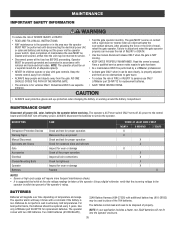
... and secured, at that time the unit may be returned to service. • Disconnect power at the operator. NOTE: The operator should be properly grounded and connected in accordance with gate controls. Pedestrians MUST use ONLY LiftMaster part 29-NP712 for wear or damage Replace CHECK AT LEAST ONCE EVERY MONTH 6 MONTHS 3 YEARS X X X X X X X X X X NOTES...
... and secured, at that time the unit may be returned to service. • Disconnect power at the operator. NOTE: The operator should be properly grounded and connected in accordance with gate controls. Pedestrians MUST use ONLY LiftMaster part 29-NP712 for wear or damage Replace CHECK AT LEAST ONCE EVERY MONTH 6 MONTHS 3 YEARS X X X X X X X X X X NOTES...

CSW24U Installation Manual
Page 48
APPENDIX STEP 8 SOLAR PANELS NOT PROVIDED. Disconnect the expansion board if it is not supported in use to ensure proper operation. We recommend LiftMaster low power draw accessories to minimize power draw, refer to cold weather and a reduced number of hours of obstructions and shading ...): Success of solar application will depend on a regular basis for areas that reach below -4˚F. Solar panels should be cleaned on type of gate operator and location of six 10W solar panels (Model SOLPNL10W12V). • Battery Tray (Model K10-36183). • Solar Battery Harness (Model K94-...
APPENDIX STEP 8 SOLAR PANELS NOT PROVIDED. Disconnect the expansion board if it is not supported in use to ensure proper operation. We recommend LiftMaster low power draw accessories to minimize power draw, refer to cold weather and a reduced number of hours of obstructions and shading ...): Success of solar application will depend on a regular basis for areas that reach below -4˚F. Solar panels should be cleaned on type of gate operator and location of six 10W solar panels (Model SOLPNL10W12V). • Battery Tray (Model K10-36183). • Solar Battery Harness (Model K94-...

CSW24U Installation Manual
Page 54
... Photoelectric Sensors Photoelectric Sensors COM LINK BA AC & BATT FAIL BACKDRIVE Shielded Twisted Pair Cable Primary/Secondary link to other gate operator Ground the shield of the cable to the chassis ground of same type and rating. Yellow Blue Black Red Field Wiring... Edge WIRING DIAGRAM 52 For continued protection against fire and electrocution: • DISCONNECT power (AC or solar and battery) BEFORE installing or servicing operator. N.O. LOCK Solenoid Lock (Optional) (not provided) LOCK Maglock (Optional) (not provided) Two 12V Solar Panels in Series + -+ - ...
... Photoelectric Sensors Photoelectric Sensors COM LINK BA AC & BATT FAIL BACKDRIVE Shielded Twisted Pair Cable Primary/Secondary link to other gate operator Ground the shield of the cable to the chassis ground of same type and rating. Yellow Blue Black Red Field Wiring... Edge WIRING DIAGRAM 52 For continued protection against fire and electrocution: • DISCONNECT power (AC or solar and battery) BEFORE installing or servicing operator. N.O. LOCK Solenoid Lock (Optional) (not provided) LOCK Maglock (Optional) (not provided) Two 12V Solar Panels in Series + -+ - ...

CSW24U Installation Manual
Page 56
... MONITORED EDGE (5 FT)** Model WR5 WRAPAROUND ROUND MONITORED EDGE (6 FT)** Model WR6 REMOTE CONTROLS LiftMaster offers a variety of LiftMaster remote controls to operate gate operator from outside by LiftMaster after 1993. Model 890MAX SECURITY+ 2.0® LEARNING REMOTE CONTROLS One button can control a gate operator and the other(s) can be programmed to Security+® or Security+ 2.0® code format...
... MONITORED EDGE (5 FT)** Model WR5 WRAPAROUND ROUND MONITORED EDGE (6 FT)** Model WR6 REMOTE CONTROLS LiftMaster offers a variety of LiftMaster remote controls to operate gate operator from outside by LiftMaster after 1993. Model 890MAX SECURITY+ 2.0® LEARNING REMOTE CONTROLS One button can control a gate operator and the other(s) can be programmed to Security+® or Security+ 2.0® code format...


