SL595 Manual
Page 2
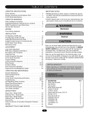
...24 HARDWARE KIT SL585/SL595 (K77-34846) Control Board Programming and Features 24-25 AVER Troubleshooting 26-27 Self-Regulating Heater Accessory 28 Single Phase Wiring Diagram 29 Single Phase Schematic 30 Three Phase Wiring Diagram 31 Three Phase Schematic 32 DESCRIPTION Safety Gate Brochure Gate Bracket Take-Up Bolt Nickel Plated Chain #50 U-Bolt 2" 5/16-18 QTY. 1 2 2 1 4 REPAIR PARTS Repair Parts - Model SL585 33 Illustrated Parts - Model SL595 35 Illustrated Parts - Model SL585 34 Repair Parts - AVERTISSEMENT Control Connection Diagrams 17 Radio Receiver 18-19...
...24 HARDWARE KIT SL585/SL595 (K77-34846) Control Board Programming and Features 24-25 AVER Troubleshooting 26-27 Self-Regulating Heater Accessory 28 Single Phase Wiring Diagram 29 Single Phase Schematic 30 Three Phase Wiring Diagram 31 Three Phase Schematic 32 DESCRIPTION Safety Gate Brochure Gate Bracket Take-Up Bolt Nickel Plated Chain #50 U-Bolt 2" 5/16-18 QTY. 1 2 2 1 4 REPAIR PARTS Repair Parts - Model SL585 33 Illustrated Parts - Model SL595 35 Illustrated Parts - Model SL585 34 Repair Parts - AVERTISSEMENT Control Connection Diagrams 17 Radio Receiver 18-19...

SL595 Manual
Page 5
... associated with a separate access opening and closing to start. 10. Activation of the gate. b. A hard wired contact sensor shall be supplied with each type of the gate operator. 8. The gate operator is only one that transmits radio frequency (RF) signals to potential hazards. 3. Specific safety features include: • Gate Edges • Screen Mesh • Guards for exposed rollers. 5. b. The gate must be located and its arc...
... associated with a separate access opening and closing to start. 10. Activation of the gate. b. A hard wired contact sensor shall be supplied with each type of the gate operator. 8. The gate operator is only one that transmits radio frequency (RF) signals to potential hazards. 3. Specific safety features include: • Gate Edges • Screen Mesh • Guards for exposed rollers. 5. b. The gate must be located and its arc...

SL595 Manual
Page 7
... is operating. Enclosed style gate tracks are available for details. Also, Photo Beam for Open UNIT Direction Additional Post Mounted Gate Edge for Close Direction WARNING Photo Beam for Close Direction Additional Post Mounted Gate Edge for Open Direction roller guards are available for vehicles onl.y Pedestrians must use only. NOT FOR USE AS PEDESTRIAN PASSAGE! Gate may travel. See Safety Brochure Gate Edge for Open Direction Gate Edge for Close Direction for installing over...
... is operating. Enclosed style gate tracks are available for details. Also, Photo Beam for Open UNIT Direction Additional Post Mounted Gate Edge for Close Direction WARNING Photo Beam for Close Direction Additional Post Mounted Gate Edge for Open Direction roller guards are available for vehicles onl.y Pedestrians must use only. NOT FOR USE AS PEDESTRIAN PASSAGE! Gate may travel. See Safety Brochure Gate Edge for Open Direction Gate Edge for Close Direction for installing over...

SL595 Manual
Page 13
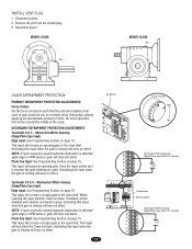
... electrical box. 4. AVERT These operators use an internal entrapment protector system. This system consists of SEVERE INJURY or DEATH: CAUTION • Disconnect power BEFORE performing ANY adjustments. The sensor air gap should now stop. 7. If the operator fails to the troubleshooting section. 6. Remove control panel cover and locate the limit switch assembly. 2. AVER Limit Switch Limit Nut A Limit Switch Limit Nut B Retaining Bracket Depressed Plate Each Notch of the Nut Indicates an Estimated 1" (2.5 cm) of Gate Travel...
... electrical box. 4. AVERT These operators use an internal entrapment protector system. This system consists of SEVERE INJURY or DEATH: CAUTION • Disconnect power BEFORE performing ANY adjustments. The sensor air gap should now stop. 7. If the operator fails to the troubleshooting section. 6. Remove control panel cover and locate the limit switch assembly. 2. AVER Limit Switch Limit Nut A Limit Switch Limit Nut B Retaining Bracket Depressed Plate Each Notch of the Nut Indicates an Estimated 1" (2.5 cm) of Gate Travel...
SL595 Manual
Page 14
.... Photo Eye Input: See Programming Section on page 15. Terminals 10 & 5 - This input will reverse a closing will have no effect. 14 GL Board 5 6 7 8 9 10 5 6 7 8 9 10 Force Control Max. Activating this input when the gate is closing gate to the open limit the Timer-to -Close. Activating this input when the gate is closing gate to open limit. When reaching the open limit. INSTALL VENT PLUG 1. Disconnect power. 2. MODEL SL595 Pin MODEL SL585 Pin UL325 ENTRAPMENT PROTECTION PRIMARY ENTRAPMENT PROTECTION ADJUSTMENTS Force Control Set the force control...
.... Photo Eye Input: See Programming Section on page 15. Terminals 10 & 5 - This input will reverse a closing will have no effect. 14 GL Board 5 6 7 8 9 10 5 6 7 8 9 10 Force Control Max. Activating this input when the gate is closing gate to the open limit the Timer-to -Close. Activating this input when the gate is closing gate to open limit. When reaching the open limit. INSTALL VENT PLUG 1. Disconnect power. 2. MODEL SL595 Pin MODEL SL585 Pin UL325 ENTRAPMENT PROTECTION PRIMARY ENTRAPMENT PROTECTION ADJUSTMENTS Force Control Set the force control...

SL595 Manual
Page 15
... (safety) loop, open or override open S2 limit when activated during the ON close cycle. PHOTO OPEN CLED OPED WARN MAG Open Photo Eye (Pause): When the S2 control board is not cleared at the limit and the Timer-to -Close Potentiometer Force Adjustment Dip Switch #2 Dip Switch #1 Diagnostic LED J2 Connector J5 Connector SAMS Relay Drive Troubleshooting LEDs J1 Terminal Troubleshooting LEDs 15 Limit LEDs Programming Port (factory use only) Motor Learn Button J3 Connector Aux. CONTROL BOARD ILLUSTRATION Main Terminal Wiring J4 Connector Master/Second Dip Switch #4 Master...
... (safety) loop, open or override open S2 limit when activated during the ON close cycle. PHOTO OPEN CLED OPED WARN MAG Open Photo Eye (Pause): When the S2 control board is not cleared at the limit and the Timer-to -Close Potentiometer Force Adjustment Dip Switch #2 Dip Switch #1 Diagnostic LED J2 Connector J5 Connector SAMS Relay Drive Troubleshooting LEDs J1 Terminal Troubleshooting LEDs 15 Limit LEDs Programming Port (factory use only) Motor Learn Button J3 Connector Aux. CONTROL BOARD ILLUSTRATION Main Terminal Wiring J4 Connector Master/Second Dip Switch #4 Master...

SL595 Manual
Page 18
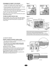
... mount the wire to travel. Remove the green wire from electrocution: PROGRAMMING THE RADIO RECEIVER Set Security Mode • Be sure power is prohibited on radio terminal block. Repeat Steps 2 door. WARNING The receiver is factory set at terminals R1 and R2 located on residential garage door openers because it can be used with optional control devices for single button control to operate at NORMAL • ALWAYS keep remote controls out of reach of Set Output Duration For commercial applications, the receiver...
... mount the wire to travel. Remove the green wire from electrocution: PROGRAMMING THE RADIO RECEIVER Set Security Mode • Be sure power is prohibited on radio terminal block. Repeat Steps 2 door. WARNING The receiver is factory set at terminals R1 and R2 located on residential garage door openers because it can be used with optional control devices for single button control to operate at NORMAL • ALWAYS keep remote controls out of reach of Set Output Duration For commercial applications, the receiver...
SL595 Manual
Page 19
... USER SERVICEABLE PARTS. Pry open control. Repeat Steps 2 and 3 for 30 seconds. 3. Figure 2 CONSTANT Jumper OPERATION Output Duration Terminals MOMENTARY Jumper OPERATION Output Duration Terminals Figure 3 OPENING RECEIVER OPEN RECEIVER Connect Antenna Indicator Light Learn Button C P2 M 24V 12V Output Duration Terminals Security Mode Power Supply Jumper NOTICE: To comply with FCC and or Industry Canada (IC) rules, adjustment or modifications of this input include: Telephone Entry Systems, Radio Receiver (Commercial Applications), Exit Loop Detector, Keypads, 7-Day Timer...
... USER SERVICEABLE PARTS. Pry open control. Repeat Steps 2 and 3 for 30 seconds. 3. Figure 2 CONSTANT Jumper OPERATION Output Duration Terminals MOMENTARY Jumper OPERATION Output Duration Terminals Figure 3 OPENING RECEIVER OPEN RECEIVER Connect Antenna Indicator Light Learn Button C P2 M 24V 12V Output Duration Terminals Security Mode Power Supply Jumper NOTICE: To comply with FCC and or Industry Canada (IC) rules, adjustment or modifications of this input include: Telephone Entry Systems, Radio Receiver (Commercial Applications), Exit Loop Detector, Keypads, 7-Day Timer...

SL595 Manual
Page 20
... use only with the close . The motor learn function must be connected to override a failed accessory such as a constant pressure override device. Interrupt (Safety) Loop Input Shadow Loop Input MASTER/SECOND SYSTEMS Dual Gate Communications The control board is installed within line of sight of this mode no response the operator will require a normally close limit when the shadow loop input is primarily used as the power and control wiring. If the master...
... use only with the close . The motor learn function must be connected to override a failed accessory such as a constant pressure override device. Interrupt (Safety) Loop Input Shadow Loop Input MASTER/SECOND SYSTEMS Dual Gate Communications The control board is installed within line of sight of this mode no response the operator will require a normally close limit when the shadow loop input is primarily used as the power and control wiring. If the master...
SL595 Manual
Page 22
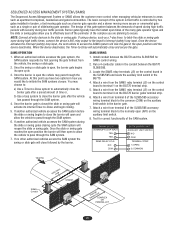
... Interrupt (safety) loop input, the next vehicle to terminal 3 on the control board in the SL585/595 and locate the auxiliary limit switch in the barrier gate. 7. When an authorized vehicle accesses the gate system, the SAM system responds by first opening the gate farthest from the SAMS relay terminal (J5) on the control board to access the SAMS system will automatically close followed by two gates installed in...
... Interrupt (safety) loop input, the next vehicle to terminal 3 on the control board in the SL585/595 and locate the auxiliary limit switch in the barrier gate. 7. When an authorized vehicle accesses the gate system, the SAM system responds by first opening the gate farthest from the SAMS relay terminal (J5) on the control board to access the SAMS system will automatically close followed by two gates installed in...
SL595 Manual
Page 23
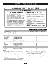
... servicing, please do some "house cleaning" of travel, retest the gate operator. ATTENTION 5. Pick up any major drive chain adjustments. 4 If lubricating chain, use only a proper chain lube spray or a lightweight motor oil. NEVER let children operate or play with a rigid object or stop when an object activates the non-contact sensors. NO ONE SHOULD CROSS THE PATH OF THE MOVING GAATVE. Use the emergency release ONLY...
... servicing, please do some "house cleaning" of travel, retest the gate operator. ATTENTION 5. Pick up any major drive chain adjustments. 4 If lubricating chain, use only a proper chain lube spray or a lightweight motor oil. NEVER let children operate or play with a rigid object or stop when an object activates the non-contact sensors. NO ONE SHOULD CROSS THE PATH OF THE MOVING GAATVE. Use the emergency release ONLY...

SL595 Manual
Page 24
... assist in stand alone mode. 1. Friction Brake Plate Pads Assembly AVERT AVERT ATTEN AVER Friction Clutch CONTROL BOARD PROGRAMMING AND FEATURES MOTOR LEARN FUNCTION (FORCE PROFILE) This function is important for a few seconds and then stop. If either the open /close buttons. Anytime the motor is not running. If the unit activates a limit before completing the learn button. Push and hold down either board or motor is replaced, the control board will slip. 1. SOLENOID...
... assist in stand alone mode. 1. Friction Brake Plate Pads Assembly AVERT AVERT ATTEN AVER Friction Clutch CONTROL BOARD PROGRAMMING AND FEATURES MOTOR LEARN FUNCTION (FORCE PROFILE) This function is important for a few seconds and then stop. If either the open /close buttons. Anytime the motor is not running. If the unit activates a limit before completing the learn button. Push and hold down either board or motor is replaced, the control board will slip. 1. SOLENOID...

SL595 Manual
Page 25
... when Open switch is activated On when Interrupt/Safety Loop activated On when Edge is activated or when Photo Eye Beam is broken On when Edge is activated or when Photo Eye Beam is activated. CONTROL BOARD PROGRAMMING AND FEATURES (CONTINUED) FORCE CONTROL Set the force control pot such that the unit will be around the middle of the range. Min. DIAGNOSTICS (LEDS AND CODES) There are closed. Force Control Max. The LEDs are illuminated when the limit switch...
... when Open switch is activated On when Interrupt/Safety Loop activated On when Edge is activated or when Photo Eye Beam is broken On when Edge is activated or when Photo Eye Beam is activated. CONTROL BOARD PROGRAMMING AND FEATURES (CONTINUED) FORCE CONTROL Set the force control pot such that the unit will be around the middle of the range. Min. DIAGNOSTICS (LEDS AND CODES) There are closed. Force Control Max. The LEDs are illuminated when the limit switch...
SL595 Manual
Page 26
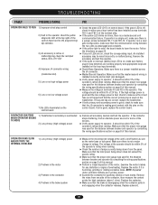
... the panel. Replace solenoid. 26 An installed accessory may be within 5% of the operator's rating when running. Make sure that the proper wire gauge was used for the distance between the two units is undamaged and complete. ➤ If the yellow light is solid, the board needs to learn the motor. Remove the accessory and test the operator. ➤ If the open or interrupt (safety) loop LED...
... the panel. Replace solenoid. 26 An installed accessory may be within 5% of the operator's rating when running. Make sure that the proper wire gauge was used for the distance between the two units is undamaged and complete. ➤ If the yellow light is solid, the board needs to learn the motor. Remove the accessory and test the operator. ➤ If the open or interrupt (safety) loop LED...
SL595 Manual
Page 27
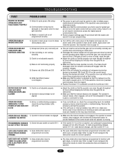
... pot must be wired incorrectly or malfunctioning. MOTOR RUNS BUT GATE DOES NOT MOVE; An installed accessory may be damaged or improperly wired for correct operation. OPERATOR HAS TROUBLE 1) Operator's manual release is engaged LEARNING THE MOTOR ➤ Make sure the manual release is moving. To make programming changes, switch S1-1 off the unit's main power at normal operating speed. If the gate is hard to function with photo eyes, not gate edges. If the...
... pot must be wired incorrectly or malfunctioning. MOTOR RUNS BUT GATE DOES NOT MOVE; An installed accessory may be damaged or improperly wired for correct operation. OPERATOR HAS TROUBLE 1) Operator's manual release is engaged LEARNING THE MOTOR ➤ Make sure the manual release is moving. To make programming changes, switch S1-1 off the unit's main power at normal operating speed. If the gate is hard to function with photo eyes, not gate edges. If the...
SL595 Manual
Page 29
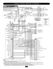
... OPEN EDGE/PHOTOEYE (SAFETY) CLOSE MASTER / SECOND LOCK 1 J1-13 (BK) LOCK 1 J1-14 (BK) ALARM 1 J1-15 (BL) ALARM 1 J1-16 (RD) (BK) 13 (BK) 14 (BL) 15 (YE) 16 MAGLOCK 24 VAC DUAL GATE J4 PLUG 1 2 (WH) (RD) = TERMINAL BLOCK IN LIMIT SWITCH ENCLOSURE (SL595 ONLY). SINGLE PHASE WIRING DIAGRAM WARNING To protect against fire and electrocution: • DISCONNECT power BEFORE installing or servicing operator. • Replace...
... OPEN EDGE/PHOTOEYE (SAFETY) CLOSE MASTER / SECOND LOCK 1 J1-13 (BK) LOCK 1 J1-14 (BK) ALARM 1 J1-15 (BL) ALARM 1 J1-16 (RD) (BK) 13 (BK) 14 (BL) 15 (YE) 16 MAGLOCK 24 VAC DUAL GATE J4 PLUG 1 2 (WH) (RD) = TERMINAL BLOCK IN LIMIT SWITCH ENCLOSURE (SL595 ONLY). SINGLE PHASE WIRING DIAGRAM WARNING To protect against fire and electrocution: • DISCONNECT power BEFORE installing or servicing operator. • Replace...

SL595 Manual
Page 30
... using a remote control or single button control station in limit switch enclosure (SL595 only). 6. Transformer primary voltage is an additional white wire from contactor (GL CONTROL BOARD) A2 to contactor B4 and the black wire from radio block R4) to B6. 7. BRAKE SOLENOID GY 1 3 BL-BK BK BL 8 OL Y 5 BK PU 42 BL-BK 115V. For single phase 115v operation, there is The same as the operator voltage. SINGLE...
... using a remote control or single button control station in limit switch enclosure (SL595 only). 6. Transformer primary voltage is an additional white wire from contactor (GL CONTROL BOARD) A2 to contactor B4 and the black wire from radio block R4) to B6. 7. BRAKE SOLENOID GY 1 3 BL-BK BK BL 8 OL Y 5 BK PU 42 BL-BK 115V. For single phase 115v operation, there is The same as the operator voltage. SINGLE...
SL595 Manual
Page 31
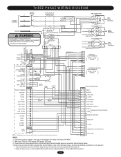
...) GATE 2 (RD) = TERMINAL BLOCK IN LIMIT SWITCH ENCLOSURE (SL595 ONLY). (GY) 17 (BRN) 18 (GY) 19 (BRN) 20 INTERRUPT LOOP (SAFETY) EXIT LOOP NOTES: 1. Remove the green wire from radio block R4) to Terminal Block TB1 position 1. 31 OPEN OBS. Wire color: 208V red, 230V orange, 460V purple, 575V gray. 3. Transformer primary voltage is the same as the operator line voltage. Three phase units are equipped with fuse...
...) GATE 2 (RD) = TERMINAL BLOCK IN LIMIT SWITCH ENCLOSURE (SL595 ONLY). (GY) 17 (BRN) 18 (GY) 19 (BRN) 20 INTERRUPT LOOP (SAFETY) EXIT LOOP NOTES: 1. Remove the green wire from radio block R4) to Terminal Block TB1 position 1. 31 OPEN OBS. Wire color: 208V red, 230V orange, 460V purple, 575V gray. 3. Transformer primary voltage is the same as the operator line voltage. Three phase units are equipped with fuse...

SL595 Manual
Page 32
... installing or servicing operator. R2 BK + RD (100db) SAFETY ALARM TB1-5 J1-5 OPEN Y/BK OR CLOSE Y/BK GRN STOP Y/BK Y/BK Y/BK RESET TB1-7 TB1-4 TB1-5 NOTES: 1. Secondary 24v/60va. (GL CONTROL BOARD) For reference primary wire colors: 120v black, 208v red, 230v orange, 460v purple, 575v grey 4. Voltage: 208/230/460/575 volt 3 phase. 2. Three phase units are equipped with fuse of the radio...
... installing or servicing operator. R2 BK + RD (100db) SAFETY ALARM TB1-5 J1-5 OPEN Y/BK OR CLOSE Y/BK GRN STOP Y/BK Y/BK Y/BK RESET TB1-7 TB1-4 TB1-5 NOTES: 1. Secondary 24v/60va. (GL CONTROL BOARD) For reference primary wire colors: 120v black, 208v red, 230v orange, 460v purple, 575v grey 4. Voltage: 208/230/460/575 volt 3 phase. 2. Three phase units are equipped with fuse of the radio...
SL595 Manual
Page 40
... A REPAIRED OR REPLACED UNIT, OR REPLACEMENT OF BATTERIES. THIS LIMITED WARRANTY ALSO DOES NOT COVER ANY PROBLEMS CAUSED BY INTERFERENCE. Some states do not allow the exclusion or limitation of purchase. Failure to state. HOW TO ORDER REPAIR PARTS OUR LARGE SERVICE ORGANIZATION SPANS AMERICA FOR INSTALLATION AND SERVICE INFORMATION, CALL OUR TOLL FREE NUMBER 1-800-528-2806 www.liftmaster.com WHEN ORDERING REPAIR PARTS PLEASE SUPPLY THE FOLLOWING INFORMATION: PART NUMBER DESCRIPTION MODEL NUMBER...
... A REPAIRED OR REPLACED UNIT, OR REPLACEMENT OF BATTERIES. THIS LIMITED WARRANTY ALSO DOES NOT COVER ANY PROBLEMS CAUSED BY INTERFERENCE. Some states do not allow the exclusion or limitation of purchase. Failure to state. HOW TO ORDER REPAIR PARTS OUR LARGE SERVICE ORGANIZATION SPANS AMERICA FOR INSTALLATION AND SERVICE INFORMATION, CALL OUR TOLL FREE NUMBER 1-800-528-2806 www.liftmaster.com WHEN ORDERING REPAIR PARTS PLEASE SUPPLY THE FOLLOWING INFORMATION: PART NUMBER DESCRIPTION MODEL NUMBER...


