
SW420 GL BOARD Manual
Page 1
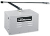
GLCONTROLLER BOARD MODEL SW420 LIGHT DUTY SWING GATE OPERATOR 2 YEAR WARRANTY Serial located on electrical box cover) Installation Date INTENDED FOR PROFESSIONAL INSTALLATION ONLY. THIS MANUAL IS TO BE LEFT WITH THE PROPERTY OWNER. MODEL SW420 IS FOR VEHICULAR PASSAGE GATES ONLY AND IS NOT INTENDED FOR PEDESTRIAN PASSAGE GATE USE. VISIT WWW.LIFTMASTER.COM TO LOCATE A PROFESSIONAL INSTALLING DEALER IN YOUR AREA.
GLCONTROLLER BOARD MODEL SW420 LIGHT DUTY SWING GATE OPERATOR 2 YEAR WARRANTY Serial located on electrical box cover) Installation Date INTENDED FOR PROFESSIONAL INSTALLATION ONLY. THIS MANUAL IS TO BE LEFT WITH THE PROPERTY OWNER. MODEL SW420 IS FOR VEHICULAR PASSAGE GATES ONLY AND IS NOT INTENDED FOR PEDESTRIAN PASSAGE GATE USE. VISIT WWW.LIFTMASTER.COM TO LOCATE A PROFESSIONAL INSTALLING DEALER IN YOUR AREA.
SW420 GL BOARD Manual
Page 2
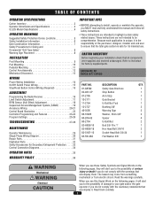
HARDWARE KIT SW420 (K77-SW420) PART NO. 01-...QTY. 1 1 1 1 1 3 2 2 4 2 1 2 1 1 WARNING Mechanical CWAUATRIONINNG Electrical CAWUATRIONNING WARNING When you see this manual and follow all components were supplied and received undamaged. Read the warnings carefully. Read them . TABLE OF CONTENTS OPERATOR SPECIFICATIONS Carton Inventory 2 Operator...33 Control Connection Diagrams 34 OPERATOR NOTES 35 WARRANTY POLICY 36 IMPORTANT NOTE • BEFORE attempting to install, operate or maintain the operator, you MUST read and fully understand this Signal Word on the following...
HARDWARE KIT SW420 (K77-SW420) PART NO. 01-...QTY. 1 1 1 1 1 3 2 2 4 2 1 2 1 1 WARNING Mechanical CWAUATRIONINNG Electrical CAWUATRIONNING WARNING When you see this manual and follow all components were supplied and received undamaged. Read the warnings carefully. Read them . TABLE OF CONTENTS OPERATOR SPECIFICATIONS Carton Inventory 2 Operator...33 Control Connection Diagrams 34 OPERATOR NOTES 35 WARRANTY POLICY 36 IMPORTANT NOTE • BEFORE attempting to install, operate or maintain the operator, you MUST read and fully understand this Signal Word on the following...

SW420 GL BOARD Manual
Page 6
...sensor for Exposed Rollers • Vertical Posts • Photoelectric Sensors • Instructional and Precautionary Signage 4. Reference owner's manual regarding placement of entrapment or obstruction exists, such as an edge sensor: a. One or more contact sensors shall be located... shall be located on each individual application. d. Therefore, safety features must be incorporated into every design. Gate systems design and installation must take into public access areas. 7. b. The Stop and/or Reset (if provided separately) must be located in contact with...
...sensor for Exposed Rollers • Vertical Posts • Photoelectric Sensors • Instructional and Precautionary Signage 4. Reference owner's manual regarding placement of entrapment or obstruction exists, such as an edge sensor: a. One or more contact sensors shall be located... shall be located on each individual application. d. Therefore, safety features must be incorporated into every design. Gate systems design and installation must take into public access areas. 7. b. The Stop and/or Reset (if provided separately) must be located in contact with...
SW420 GL BOARD Manual
Page 7
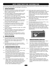
...grade and for barbed wire shall not be less than 6 feet (1.83 m) above grade. 1.5 An existing gate latch shall be disabled when a manually operated gate is required to perform their intended function. 3.1.5 All gates shall be designed with security related parameters specific to the application in question. ... disconnected. 3.1.4 Positive stops shall be required to limit travel to the designed fully open and fully closed positions. These stops shall be installed at either the fully open position or the fully closed position, shall not exceed 2-1/4 inches (57 mm), refer to ASTM F2200 for...
...grade and for barbed wire shall not be less than 6 feet (1.83 m) above grade. 1.5 An existing gate latch shall be disabled when a manually operated gate is required to perform their intended function. 3.1.5 All gates shall be designed with security related parameters specific to the application in question. ... disconnected. 3.1.4 Positive stops shall be required to limit travel to the designed fully open and fully closed positions. These stops shall be installed at either the fully open position or the fully closed position, shall not exceed 2-1/4 inches (57 mm), refer to ASTM F2200 for...
SW420 GL BOARD Manual
Page 12
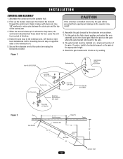
... to drop down, the control arm should swivel freely about the hub. Attach the gate bracket with clevis pin. INSTALLATION WARNING CONTROL ARM ASSEMBLY 1. Push up the manual release pin from opening and damage to the closed position and extend the arm AVERT assembly out to the operator may... result! 6. When the manual release pin is installed incorrectly, the gate will mount to pivot at the appropriate height. 9. Mark the point on the gate where the gate bracket will be installed on Operator Arm Stop (Left Open) Arm Stop Kit K75-18624...
... to drop down, the control arm should swivel freely about the hub. Attach the gate bracket with clevis pin. INSTALLATION WARNING CONTROL ARM ASSEMBLY 1. Push up the manual release pin from opening and damage to the closed position and extend the arm AVERT assembly out to the operator may... result! 6. When the manual release pin is installed incorrectly, the gate will mount to pivot at the appropriate height. 9. Mark the point on the gate where the gate bracket will be installed on Operator Arm Stop (Left Open) Arm Stop Kit K75-18624...

SW420 GL BOARD Manual
Page 13
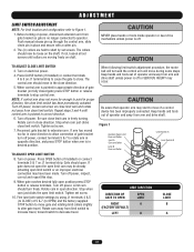
The arm should now be free and the gate can be opened or closed normally. Figure 1 Clevis Pin Hairpin Cotter Control Arm Drive Hub Release Pin 13 Disconnect the control arm from the gate, so the gate can be manually opened and closed . NOTE: If desired, a padlock can be used in place of the clevis pin to drop down through the hub. INSTALLATION MECHANICAL DISCONNECT The operator can be disconnected from the drive hub by removing the hairpin cotter and then the clevis pin and allowing the manual release pin to hold the manual release pin in place.
The arm should now be free and the gate can be opened or closed normally. Figure 1 Clevis Pin Hairpin Cotter Control Arm Drive Hub Release Pin 13 Disconnect the control arm from the gate, so the gate can be manually opened and closed . NOTE: If desired, a padlock can be used in place of the clevis pin to drop down through the hub. INSTALLATION MECHANICAL DISCONNECT The operator can be disconnected from the drive hub by removing the hairpin cotter and then the clevis pin and allowing the manual release pin to hold the manual release pin in place.
SW420 GL BOARD Manual
Page 17
...switch to increase travel . Reconnect gate bracket to Figure 1. 1. Limit cam should now be already actuating open limit cam may occur. Push manual release pin up through the control arm, slide clevis pin in approximate direction of operator and away from close direction. 5. The collars should...on shaft. Be sure close limit switch. Stop when cam just clicks close limit cam is pointed in desired position. Press OPEN button (if installed) or connect terminals 5 & 7 on power. Rotate cam away from arm and drive shaft. Turn on close limit cam and rotate nut...
...switch to increase travel . Reconnect gate bracket to Figure 1. 1. Limit cam should now be already actuating open limit cam may occur. Push manual release pin up through the control arm, slide clevis pin in approximate direction of operator and away from close direction. 5. The collars should...on shaft. Be sure close limit switch. Stop when cam just clicks close limit cam is pointed in desired position. Press OPEN button (if installed) or connect terminals 5 & 7 on power. Rotate cam away from arm and drive shaft. Turn on close limit cam and rotate nut...

SW420 GL BOARD Manual
Page 27
... & J5-2. If the high voltage power is good and the low voltage power is a control board next to move . If all is a jumper installed across terminals J1-3 & J1-5 of the operator's rating when running . Problem in a dual gate dip switches. Perform a visual inspection of the communication ... the green LED is intact (not damaged). Low or no low voltage power. An installed accessory may be within 5% of 24 Vac. No LEDs illuminated on control board. It should be within 5% of this manual. This voltage should be within 5% of the control board. Check the green LED ...
... & J5-2. If the high voltage power is good and the low voltage power is a control board next to move . If all is a jumper installed across terminals J1-3 & J1-5 of the operator's rating when running . Problem in a dual gate dip switches. Perform a visual inspection of the communication ... the green LED is intact (not damaged). Low or no low voltage power. An installed accessory may be within 5% of 24 Vac. No LEDs illuminated on control board. It should be within 5% of this manual. This voltage should be within 5% of the control board. Check the green LED ...

SW420 GL BOARD Manual
Page 34
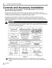
... that you follow the instructions provided by the manufacturer when installing and adjusting any control device. Installation device instructions - SEE OWNERS MANUAL FOR WIRING DISTANCES AND WIRE GAUGE INFORMATION. Also, always install the controls where the user has full view of gate operation... EYE INPUT (N.O.) RESIDENTIAL RADIO (SINGLE BUTTON) INPUT (N.O.) SW420 Operator 34 always follow the UL guidelines presented throughout the manual. The following instructions are contrary to operate the gate system, MUST be installed where the user cannot come into contact with the gate...
... that you follow the instructions provided by the manufacturer when installing and adjusting any control device. Installation device instructions - SEE OWNERS MANUAL FOR WIRING DISTANCES AND WIRE GAUGE INFORMATION. Also, always install the controls where the user has full view of gate operation... EYE INPUT (N.O.) RESIDENTIAL RADIO (SINGLE BUTTON) INPUT (N.O.) SW420 Operator 34 always follow the UL guidelines presented throughout the manual. The following instructions are contrary to operate the gate system, MUST be installed where the user cannot come into contact with the gate...

SW420 S3 BOARD Manual
Page 2
... Safety Precautions for Swing Gates and Ornamental "Grill Type" Gates 8 Preparing the Installation 9 Pre-Installation Check List 9 Wiring Specifications 9 Operator Preparation 10 Installation 11 Post Mount Installation 11 Pad Mount Installation 13 Pedestal Mount Installation 14 Control Arm Assembly 15 System Features 17 Visible/Audible Devices 17 Single/Three ... Switch #1: Operator Programming 19 Switch #2: Timer to Close 20 Limit Switch Adjustments 21 Controls and Accessory Installation 24 Manual Operation 25 Required Maintenance 26 Troubleshooting 27 Doc 01-G0610 Rev A
... Safety Precautions for Swing Gates and Ornamental "Grill Type" Gates 8 Preparing the Installation 9 Pre-Installation Check List 9 Wiring Specifications 9 Operator Preparation 10 Installation 11 Post Mount Installation 11 Pad Mount Installation 13 Pedestal Mount Installation 14 Control Arm Assembly 15 System Features 17 Visible/Audible Devices 17 Single/Three ... Switch #1: Operator Programming 19 Switch #2: Timer to Close 20 Limit Switch Adjustments 21 Controls and Accessory Installation 24 Manual Operation 25 Required Maintenance 26 Troubleshooting 27 Doc 01-G0610 Rev A
SW420 S3 BOARD Manual
Page 6
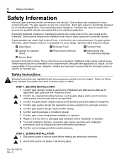
...-electric sensors, vertical posts and enclosed tracks, are highlighted with each application is unique, it is only one component. STEP 1: BEFORE INSTALLATION 1 Confirm gate operator model is specified by Installation and Maintenance Manual for an individual application. Therefore, safety features must take into every design. Safety Instructions Selected Instructions are specified. 3 Confirm the...
...-electric sensors, vertical posts and enclosed tracks, are highlighted with each application is unique, it is only one component. STEP 1: BEFORE INSTALLATION 1 Confirm gate operator model is specified by Installation and Maintenance Manual for an individual application. Therefore, safety features must take into every design. Safety Instructions Selected Instructions are specified. 3 Confirm the...

SW420 S3 BOARD Manual
Page 7
...FOR GATE OPERATORS USING NON-CONTACT SENSOR(S) See instruction supplied with end user. In any case, the device must be conspicuous. 7 Install operator inside fence line. FOR GATE OPERATORS USING CONTACT SENSOR(S) One or more than one sensor should be used for proper placement. ...entrapment or obstruction, then more sensors shall be taken to reduce the risk of nuisance tripping of gate system. 3 Leave Installation and Maintenance Manual and Safety Information with sensor for both . SECONDARY ENTRAPMENT PROTECTION It is not interfered with a gate edge transmitter, care must...
...FOR GATE OPERATORS USING NON-CONTACT SENSOR(S) See instruction supplied with end user. In any case, the device must be conspicuous. 7 Install operator inside fence line. FOR GATE OPERATORS USING CONTACT SENSOR(S) One or more than one sensor should be used for proper placement. ...entrapment or obstruction, then more sensors shall be taken to reduce the risk of nuisance tripping of gate system. 3 Leave Installation and Maintenance Manual and Safety Information with sensor for both . SECONDARY ENTRAPMENT PROTECTION It is not interfered with a gate edge transmitter, care must...

SW420 S3 BOARD Manual
Page 15
... sides of the gate. The gate bracket should swivel freely about the hub. Be sure that the arm assembly is allowed to the closed gate. Installation 15 Control Arm Assembly 1 Assemble the control arm to mount the arm stop on the arm. 8 Put the gate in Figure 9. stop . Use the ...Rev A Left Refer to Figure 9 to the gate. See Figure 9. 2 Push up any play between the clevis pin and the top of place. 4 When the manual release pin is level and able to operate smoothly. 9 The gate bracket must be prevented from below the hub and through the control arm. IMPORTANT...
... sides of the gate. The gate bracket should swivel freely about the hub. Be sure that the arm assembly is allowed to the closed gate. Installation 15 Control Arm Assembly 1 Assemble the control arm to mount the arm stop on the arm. 8 Put the gate in Figure 9. stop . Use the ...Rev A Left Refer to Figure 9 to the gate. See Figure 9. 2 Push up any play between the clevis pin and the top of place. 4 When the manual release pin is level and able to operate smoothly. 9 The gate bracket must be prevented from below the hub and through the control arm. IMPORTANT...

SW420 S3 BOARD Manual
Page 18
... OR EXTERNAL SYSTEMS The operator will restart the gate. All the system programming is the main circuit board for the operator. Either a manual device such as opening or security loop detectors are activated. Doc 01-G0610 Rev A A second obstruction will not activate from any automatic...NOTE: This feature is defeated when either function as a single button or to function as open and close . See Controls and Accessory Install on this circuit. Circuitry OPEN ONLY CIRCUIT Separate open circuits for the system. It contains all the logic and intelligence for line-of...
... OR EXTERNAL SYSTEMS The operator will restart the gate. All the system programming is the main circuit board for the operator. Either a manual device such as opening or security loop detectors are activated. Doc 01-G0610 Rev A A second obstruction will not activate from any automatic...NOTE: This feature is defeated when either function as a single button or to function as open and close . See Controls and Accessory Install on this circuit. Circuitry OPEN ONLY CIRCUIT Separate open circuits for the system. It contains all the logic and intelligence for line-of...
SW420 S3 BOARD Manual
Page 24
always follow the UL guidelines presented throughout the manual. WARNING All controls that secondary safeties always be used here and the radio (R2) Is wired here internally by the manufacturer when installing and adjusting any case, the device must be used to be used . In any control...system must sense people. The following instructions are field connections. We strongly recommend that bypasses the processor and may be ordered factory installed. If these instructions are contrary to the advice given here, call the factory 01-G0610F16 NOTE: Numbers shown inside a box ...
always follow the UL guidelines presented throughout the manual. WARNING All controls that secondary safeties always be used here and the radio (R2) Is wired here internally by the manufacturer when installing and adjusting any case, the device must be used to be used . In any control...system must sense people. The following instructions are field connections. We strongly recommend that bypasses the processor and may be ordered factory installed. If these instructions are contrary to the advice given here, call the factory 01-G0610F16 NOTE: Numbers shown inside a box ...

