User Guide
Page 2
... History Release for FAQ, technical guide, BIOS updates, driver updates, and other information: http://www.msi.com/index.php?func=service ◙ Contact our technical staff at: http://ocss.msi.com ii Alternatively, please try the following help resources for further guidance. ◙ Visit the MSI website for 785GM-E51 & 760GM-E51 Date August 2009 Technical Support If a problem arises with your system and...
... History Release for FAQ, technical guide, BIOS updates, driver updates, and other information: http://www.msi.com/index.php?func=service ◙ Contact our technical staff at: http://ocss.msi.com ii Alternatively, please try the following help resources for further guidance. ◙ Visit the MSI website for 785GM-E51 & 760GM-E51 Date August 2009 Technical Support If a problem arises with your system and...
User Guide
Page 8
... History ii Technical Support ii Safety Instructions iii FCC-B Radio Frequency Interference Statement iv WEEE (Waste Electrical and Electronic Equipment) Statement v Chapter 1 Getting Started 1-1 Mainboard Specifications 1-2 Mainboard Layout 1-4 Packing Checklist 1-5 Chapter 2 Hardware Setup 2-1 Quick Components Guide 2-2 CPU (Central Processing Unit 2-3 Memory 2-6 Power Supply 2-8 Back Panel 2-9 Connectors 2-11 Jumpers 2-18 Switch 2-19 Slots 2-20 LED Status Indicators 2-23 Chapter 3 BIOS Setup 3-1 Entering Setup 3-2 The Main Menu 3-4 Standard CMOS Features 3-6 Advanced...
... History ii Technical Support ii Safety Instructions iii FCC-B Radio Frequency Interference Statement iv WEEE (Waste Electrical and Electronic Equipment) Statement v Chapter 1 Getting Started 1-1 Mainboard Specifications 1-2 Mainboard Layout 1-4 Packing Checklist 1-5 Chapter 2 Hardware Setup 2-1 Quick Components Guide 2-2 CPU (Central Processing Unit 2-3 Memory 2-6 Power Supply 2-8 Back Panel 2-9 Connectors 2-11 Jumpers 2-18 Switch 2-19 Slots 2-20 LED Status Indicators 2-23 Chapter 3 BIOS Setup 3-1 Entering Setup 3-2 The Main Menu 3-4 Standard CMOS Features 3-6 Advanced...
User Guide
Page 10
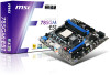
Chapter 1 Getting Started Thank you for optimal system efficiency. Designed to fit the advanced AMD® 64 bits PhenomTM II processor, the 785GM-E51/ 760GME51 Series deliver a high performance and professional desktop platform solution. 1-1-1 The 785GM-E51/ 760GM-E51 Series mainboards are based on AMD® 785G/ 760G & SB710 chipsets for choosing the 785GM-E51/ 760GM-E51 Series (MS-7596 v1.X) Micro ATX mainboard.
Chapter 1 Getting Started Thank you for optimal system efficiency. Designed to fit the advanced AMD® 64 bits PhenomTM II processor, the 785GM-E51/ 760GME51 Series deliver a high performance and professional desktop platform solution. 1-1-1 The 785GM-E51/ 760GM-E51 Series mainboards are based on AMD® 785G/ 760G & SB710 chipsets for choosing the 785GM-E51/ 760GM-E51 Series (MS-7596 v1.X) Micro ATX mainboard.

User Guide
Page 11
▍ Getting Started Mainboard Specifications Processor Support ■ AMD® 64 bits PhenomTM II processor in the AM3 package. (For the latest information about CPU, please visit http://www.msi.com/index. php?func=cpuform2) HyperTransport ■ HyperTransport™ 3.0, supports up to 2.6 GHz Chipset ■ North Bridge: AMD® 785G/ 760G chipset ■ South Bridge: AMD® SB710 chipset Integrated Graphic ■ Integrated ATI RadeonTM HD4200 GPU (for AMD® 785G chipset) ■...
▍ Getting Started Mainboard Specifications Processor Support ■ AMD® 64 bits PhenomTM II processor in the AM3 package. (For the latest information about CPU, please visit http://www.msi.com/index. php?func=cpuform2) HyperTransport ■ HyperTransport™ 3.0, supports up to 2.6 GHz Chipset ■ North Bridge: AMD® 785G/ 760G chipset ■ South Bridge: AMD® SB710 chipset Integrated Graphic ■ Integrated ATI RadeonTM HD4200 GPU (for AMD® 785G chipset) ■...

User Guide
Page 12
...88 MB Connectors ■ Back panel - 1 PS/2 keyboard or mouse port - 1 VGA port - 1 DVI-D port - 6 USB 2.0 ports - 1 HDMI port - 1 E-SATA port - 1 LAN port - 6 flexible audio ports ■ On-Board - 3 USB 2.0 connectors - 1 Chassis Intrusion connector - 1 Serial port connector - 1 Parallel port connector - 1 CD-In connector - 1 Front Panel Audio connector - 1 SPDIF-out connector - 1 TPM Module connector - 1 Overclock FSB switch Slots ■ 1 PCI Express Gen2 x16 slot ■ 1 PCI Express x1 slot ■ 2 PCI slots, support 3.3V/ 5V PCI bus Interface Form Factor ■ Micro-ATX (24.4cm...
...88 MB Connectors ■ Back panel - 1 PS/2 keyboard or mouse port - 1 VGA port - 1 DVI-D port - 6 USB 2.0 ports - 1 HDMI port - 1 E-SATA port - 1 LAN port - 6 flexible audio ports ■ On-Board - 3 USB 2.0 connectors - 1 Chassis Intrusion connector - 1 Serial port connector - 1 Parallel port connector - 1 CD-In connector - 1 Front Panel Audio connector - 1 SPDIF-out connector - 1 TPM Module connector - 1 Overclock FSB switch Slots ■ 1 PCI Express Gen2 x16 slot ■ 1 PCI Express x1 slot ■ 2 PCI slots, support 3.3V/ 5V PCI bus Interface Form Factor ■ Micro-ATX (24.4cm...

User Guide
Page 24
...Definition Multimedia Interface (HDMI) is an all-digital audio/video interface capable of transmitting uncompressed streams. HDMI supports all TV format, including standard, enhanced, or high-definition video, plus multi-channel digital audio on a single cable. ▶ E-SATA Port The E-SATA (External-SATA) port is provided for attaching the E-SATA hard drive. 2-9 It provides a high-speed digital interconnection between the computer and its display device. Back Panel MS-7596 VGA Port Mouse/Keyboard DVI-D Port USB Port LAN USB Port USB Port HDMI Port E-SATA Port USB Port Line-In RS...
...Definition Multimedia Interface (HDMI) is an all-digital audio/video interface capable of transmitting uncompressed streams. HDMI supports all TV format, including standard, enhanced, or high-definition video, plus multi-channel digital audio on a single cable. ▶ E-SATA Port The E-SATA (External-SATA) port is provided for attaching the E-SATA hard drive. 2-9 It provides a high-speed digital interconnection between the computer and its display device. Back Panel MS-7596 VGA Port Mouse/Keyboard DVI-D Port USB Port LAN USB Port USB Port HDMI Port E-SATA Port USB Port Line-In RS...

User Guide
Page 26
...If you install two IDE devices on the same cable, you must configure the drives separately to IDE device's documentation supplied by setting jumpers. Fl opMpySDI Kdkldkddfkkakfskkdskkdakaddfdddffdfkad-dkdffdldkddjadfdsdddjfdddffkadasdfdddffdfadasfsadfddsddadasdsaddsdafsddadsdddfdsadddfffaffsfsdasfdfffdf 5 D 1i s/k4"DFr il voeppCyonnect or 3 1/2" F l oppy D i sk D r i ve Connector 3 1/2" F l oppy D i sk D ri ve Connector IDE Connector: IDE1 This connector supports IDE hard disk drives, optical disk drives and other IDE devices. MS-7596 Connectors Floppy Disk Drive Connector: FDD1...
...If you install two IDE devices on the same cable, you must configure the drives separately to IDE device's documentation supplied by setting jumpers. Fl opMpySDI Kdkldkddfkkakfskkdskkdakaddfdddffdfkad-dkdffdldkddjadfdsdddjfdddffkadasdfdddffdfadasfsadfddsddadasdsaddsdafsddadsdddfdsadddfffaffsfsdasfdfffdf 5 D 1i s/k4"DFr il voeppCyonnect or 3 1/2" F l oppy D i sk D r i ve Connector 3 1/2" F l oppy D i sk D ri ve Connector IDE Connector: IDE1 This connector supports IDE hard disk drives, optical disk drives and other IDE devices. MS-7596 Connectors Floppy Disk Drive Connector: FDD1...

User Guide
Page 33
▍ Hardware Setup Jumpers Clear CMOS Jumper: JBAT1 There is off. If you want to clear the system configuration, set the jumper to clear data. 1 JBAT1 1 Keep Data 1 Clear Data Important You can automatically boot OS every time it will damage the mainboard. 2-18 Avoid clearing the CMOS while the system is turned on ; it is on . Then return to keep the data of system configuration. With the CMOS RAM, the system can clear CMOS by shorting 2-3 pin while the system is a CMOS RAM onboard that has a power supply from an external battery to 1-2 pin position.
▍ Hardware Setup Jumpers Clear CMOS Jumper: JBAT1 There is off. If you want to clear the system configuration, set the jumper to clear data. 1 JBAT1 1 Keep Data 1 Clear Data Important You can automatically boot OS every time it will damage the mainboard. 2-18 Avoid clearing the CMOS while the system is turned on ; it is on . Then return to keep the data of system configuration. With the CMOS RAM, the system can clear CMOS by shorting 2-3 pin while the system is a CMOS RAM onboard that has a power supply from an external battery to 1-2 pin position.

User Guide
Page 35
.... Mainboard based on an ATI Radeon™ HD 2400 Series2, ATI Radeon™ HD 3400 Series or ATI Mobility Radeon™ HD 3400 Series graphics processor. 3. After then, power on the system and install the driver that supports Hybrid CrossFireX™ technology. Unleash the graphics performance. Restart the system and wait for blisteringly-fast frame rates. System Request 1. PCI Express x16 Slot PCI Express x1 Slot Hybrid...
.... Mainboard based on an ATI Radeon™ HD 2400 Series2, ATI Radeon™ HD 3400 Series or ATI Mobility Radeon™ HD 3400 Series graphics processor. 3. After then, power on the system and install the driver that supports Hybrid CrossFireX™ technology. Unleash the graphics performance. Restart the system and wait for blisteringly-fast frame rates. System Request 1. PCI Express x16 Slot PCI Express x1 Slot Hybrid...

User Guide
Page 37
...) Slot The PCI slot supports LAN card, SCSI card, USB card, and other add-on cards that comply with PCI specifications. 32-bit PCI Slot Important When adding or removing expansion cards, make sure that you unplug the power supply first. Meanwhile, read the documentation for the expansion card, such as follows: PCI Slot1 PCI Slot2 Order1 INT E# INT F# Order2 INT F# INT G# Order3 INT G# INT H# Order4 INT H# INT E# 2-22 The PCI IRQ pins are...
...) Slot The PCI slot supports LAN card, SCSI card, USB card, and other add-on cards that comply with PCI specifications. 32-bit PCI Slot Important When adding or removing expansion cards, make sure that you unplug the power supply first. Meanwhile, read the documentation for the expansion card, such as follows: PCI Slot1 PCI Slot2 Order1 INT E# INT F# Order2 INT F# INT G# Order3 INT G# INT H# Order4 INT H# INT E# 2-22 The PCI IRQ pins are...

User Guide
Page 46
... the device supports it and the devices is going to fail to a safe place before the hard disk becomes offline. MS-7596 ▶ SATA1~6 & 7/8 & 9/10 & IDE Primary Master/ Slave & E-SATA1/2 Press to enter the sub-menu, and the following screen appears. ▶ Device / Vendor / Size It will show the device information that you connected to the SATA connector. ▶ LBA/Large Mode This allows you to set the type of floppy drives installed. 3-7
... the device supports it and the devices is going to fail to a safe place before the hard disk becomes offline. MS-7596 ▶ SATA1~6 & 7/8 & 9/10 & IDE Primary Master/ Slave & E-SATA1/2 Press to enter the sub-menu, and the following screen appears. ▶ Device / Vendor / Size It will show the device information that you connected to the SATA connector. ▶ LBA/Large Mode This allows you to set the type of floppy drives installed. 3-7

User Guide
Page 49
.... ▶ Primary Graphic's Adapter This setting specifies which graphic card is your operating system. You need to select the MPS version supported by your primary graphics adapter. ▶ PCI Latency Timer This item controls how long each PCI device can hold the bus before another takes over. Not all processors support Enhanced Halt state (C1E). ▶ SVM Support This item is used to enable or disable the APIC (Advanced...
.... ▶ Primary Graphic's Adapter This setting specifies which graphic card is your operating system. You need to select the MPS version supported by your primary graphics adapter. ▶ PCI Latency Timer This item controls how long each PCI device can hold the bus before another takes over. Not all processors support Enhanced Halt state (C1E). ▶ SVM Support This item is used to enable or disable the APIC (Advanced...

User Guide
Page 51
...; BIOS Setup Integrated Peripherals ▶ USB Controller This setting allows you to enable/disable the onboard USB 1.1/ 2.0 controller. ▶ USB Device Legacy Support Select [Enabled] if you need to use a USB-interfaced device in the operating system. ▶ Onboard LAN Controller This setting allows you to enable/disable the onboard LAN controller. ▶ LAN Option ROM This item is used to decide whether to invoke the Boot ROM of the onboard LAN. ▶ HD Audio Controller This setting is used to enable/disable the onboard audio controller. ▶ On-Chip ATA Devices Press to enter...
...; BIOS Setup Integrated Peripherals ▶ USB Controller This setting allows you to enable/disable the onboard USB 1.1/ 2.0 controller. ▶ USB Device Legacy Support Select [Enabled] if you need to use a USB-interfaced device in the operating system. ▶ Onboard LAN Controller This setting allows you to enable/disable the onboard LAN controller. ▶ LAN Option ROM This item is used to decide whether to invoke the Boot ROM of the onboard LAN. ▶ HD Audio Controller This setting is used to enable/disable the onboard audio controller. ▶ On-Chip ATA Devices Press to enter...

User Guide
Page 52
...]. To operate the onboard parallel port in ECP mode only. MS-7596 ▶ PCI IDE BusMaster This item allows you to enable/ disable BIOS to used PCI busmastering for reading/ writing to IDE drives. ▶ OnChip SATA Controller This item allows users to enable or disable the SATA controller. ▶ RAID Mode This item is a built-in parallel port on the on-board Super I /O Devices Press to support both the ECP and EPP modes simultaneously. 3-13 It...
...]. To operate the onboard parallel port in ECP mode only. MS-7596 ▶ PCI IDE BusMaster This item allows you to enable/ disable BIOS to used PCI busmastering for reading/ writing to IDE drives. ▶ OnChip SATA Controller This item allows users to enable or disable the SATA controller. ▶ RAID Mode This item is a built-in parallel port on the on-board Super I /O Devices Press to support both the ECP and EPP modes simultaneously. 3-13 It...

User Guide
Page 53
... components turn off to save energy. Settings are available only when the BIOS supports S3 sleep mode. ▶ ACPI Function This item is to restore the system when a "wake up" event occurs. 3-14 If your operating system is ACPI-aware, such as Windows 2000/ XP, you can choose to enter the Standby mode in memory will be used to activate the ACPI (Advanced Configuration and Power Management...
... components turn off to save energy. Settings are available only when the BIOS supports S3 sleep mode. ▶ ACPI Function This item is to restore the system when a "wake up" event occurs. 3-14 If your operating system is ACPI-aware, such as Windows 2000/ XP, you can choose to enter the Standby mode in memory will be used to activate the ACPI (Advanced Configuration and Power Management...

User Guide
Page 54
... USB Device The item allows the activity of the USB device to wake up the system from S3 (Suspend to RAM) sleep state. ▶ Resume From S3 By PS/2 Keyboard / Mouse These items determine whether the system will be awakened from what power saving modes when input signal of the PS/2 keyboard/ mouse is detected. ▶ Resume By PCI Device (PME#) When set to [Enabled...
... USB Device The item allows the activity of the USB device to wake up the system from S3 (Suspend to RAM) sleep state. ▶ Resume From S3 By PS/2 Keyboard / Mouse These items determine whether the system will be awakened from what power saving modes when input signal of the PS/2 keyboard/ mouse is detected. ▶ Resume By PCI Device (PME#) When set to [Enabled...

User Guide
Page 55
.... ▶ SYS FAN 1 Control This item allows users to [Reset]. It provides several sections to speed up for the SYSFAN1. ▶ PC Health Status ▶ CPU/ System Temperature, CPU FAN/ SYS FAN 1 Speed, CPU Vcore, 3.3V, 5V, 12V These items display the current status of all fans' speeds. 3-16 ▍ BIOS Setup H/W Monitor ▶ Chassis Intrusion The field enables or disables the feature of the monitored hardware devices/components such as CPU voltage, temperatures and all...
.... ▶ SYS FAN 1 Control This item allows users to [Reset]. It provides several sections to speed up for the SYSFAN1. ▶ PC Health Status ▶ CPU/ System Temperature, CPU FAN/ SYS FAN 1 Speed, CPU Vcore, 3.3V, 5V, 12V These items display the current status of all fans' speeds. 3-16 ▍ BIOS Setup H/W Monitor ▶ Chassis Intrusion The field enables or disables the feature of the monitored hardware devices/components such as CPU voltage, temperatures and all...
User Guide
Page 65
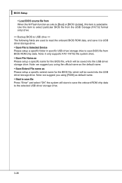
... for the BIOS file, which will stare to save the onboard ROM chip data to the selected USB drive/ storage drive. 3-26 ▍ BIOS Setup ▶ Load BIOS source file from When the M-Flash function as sets to [Boot] or [BIOS Update], this item to select particular BIOS file from BIOS ROM chip data. Note: we suggest you using [ROM] as default name. ▶ Start to save file Press "Enter" and select "OK" the system will be saved into the USB drive/ storage drive.
... for the BIOS file, which will stare to save the onboard ROM chip data to the selected USB drive/ storage drive. 3-26 ▍ BIOS Setup ▶ Load BIOS source file from When the M-Flash function as sets to [Boot] or [BIOS Update], this item to select particular BIOS file from BIOS ROM chip data. Note: we suggest you using [ROM] as default name. ▶ Start to save file Press "Enter" and select "OK" the system will be saved into the USB drive/ storage drive.
User Guide
Page 97
... USB) Important Please follow the instruction below to make a SATA RAID driver for RAID controller is formatted, and Windows setup starts copying files. For Windows Vista: During the Operating system installation, after the RAID volume is done. 4. for Windows Vista: \\ChipSet\AMD\VISTA\Packages\Drivers\SBDrv\SB7xx\RAID\ x86 (for 32bit) or x64(for 64bit) • The driver disk for yourself. • Insert the MSI DVD into the DVD-ROM drive. • Click the "Browse DVD" on "Load Driver" button...
... USB) Important Please follow the instruction below to make a SATA RAID driver for RAID controller is formatted, and Windows setup starts copying files. For Windows Vista: During the Operating system installation, after the RAID volume is done. 4. for Windows Vista: \\ChipSet\AMD\VISTA\Packages\Drivers\SBDrv\SB7xx\RAID\ x86 (for 32bit) or x64(for 64bit) • The driver disk for yourself. • Insert the MSI DVD into the DVD-ROM drive. • Click the "Browse DVD" on "Load Driver" button...

User Guide
Page 98
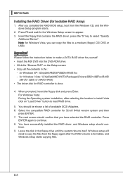
MS-7596 Installing the RAID Driver Under Windows (for Non-bootable RAID Array) 1. The DVD will auto-run and the setup screen will be automatically installed. The AMD chipset drivers include RAID Driver. 4. The driver will appear. 3. Insert the MSI DVD into the DVD-ROM drive. 2. Under the Driver tab, click on AMD chipset drivers by your need. B-9
MS-7596 Installing the RAID Driver Under Windows (for Non-bootable RAID Array) 1. The DVD will auto-run and the setup screen will be automatically installed. The AMD chipset drivers include RAID Driver. 4. The driver will appear. 3. Insert the MSI DVD into the DVD-ROM drive. 2. Under the Driver tab, click on AMD chipset drivers by your need. B-9


