User Guide
Page 2
... owners. ■ MSI® is registered trademark of Micro-Star Int'l Co.,Ltd. ■ NVIDIA® is registered trademark of NVIDIA Corporation. ■ ATI® is registered trademark of ATI Technologies, Inc. ■ AMD® is registered trademarks of AMD Corporation. ■ Intel...trademark of purchase or local distributor. Alternatively, please try the following help resources for further guidance. ◙ Visit the MSI website for 785GM-E51 & 760GM-E51 Date August 2009 Technical Support If a problem arises with your place of Novell, Inc. We take every care in...
... owners. ■ MSI® is registered trademark of Micro-Star Int'l Co.,Ltd. ■ NVIDIA® is registered trademark of NVIDIA Corporation. ■ ATI® is registered trademark of ATI Technologies, Inc. ■ AMD® is registered trademarks of AMD Corporation. ■ Intel...trademark of purchase or local distributor. Alternatively, please try the following help resources for further guidance. ◙ Visit the MSI website for 785GM-E51 & 760GM-E51 Date August 2009 Technical Support If a problem arises with your place of Novell, Inc. We take every care in...

User Guide
Page 3
MS-7596 Safety Instructions ■ Always read the safety instructions carefully. ■ Keep this User's Manual for future reference. ■ Keep this equipment away from overheating. thing ...
MS-7596 Safety Instructions ■ Always read the safety instructions carefully. ■ Keep this User's Manual for future reference. ■ Keep this equipment away from overheating. thing ...

User Guide
Page 4
... This equipment has been tested and found to comply with the limits for a Class B digital device, pursuant to comply with the emission limits. Micro-Star International MS-7596 This device complies with the instructions, may cause harmful interference to which can radiate radio frequency energy and, if not installed and used in...
... This equipment has been tested and found to comply with the limits for a Class B digital device, pursuant to comply with the emission limits. Micro-Star International MS-7596 This device complies with the instructions, may cause harmful interference to which can radiate radio frequency energy and, if not installed and used in...

User Guide
Page 5
... à rappeler ceci... MSI hat europaweit verschiedene Sammel- Par conséquent vous pouvez retourner localement ces matériels dans les points de collecte. MS-7596 WEEE (Waste Electrical and Electronic Equipment) Statement ENGLISH To protect the ...global environment and as municipal waste anymore and manufacturers of covered electronic equipment will comply with the product take back such products at the end of life of MSI-branded products that ... MSI WEEE 2002/96/EC 13 2005 MSI MSI...
... à rappeler ceci... MSI hat europaweit verschiedene Sammel- Par conséquent vous pouvez retourner localement ces matériels dans les points de collecte. MS-7596 WEEE (Waste Electrical and Electronic Equipment) Statement ENGLISH To protect the ...global environment and as municipal waste anymore and manufacturers of covered electronic equipment will comply with the product take back such products at the end of life of MSI-branded products that ... MSI WEEE 2002/96/EC 13 2005 MSI MSI...
User Guide
Page 8
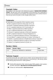
▍ Preface ▍ Contents Copyright Notice ii Trademarks ii Revision History ii Technical Support ii Safety Instructions iii FCC-B Radio Frequency Interference Statement iv WEEE (Waste Electrical and Electronic Equipment) Statement v Chapter 1 Getting Started 1-1 Mainboard Specifications 1-2 Mainboard Layout 1-4 Packing Checklist 1-5 Chapter 2 Hardware Setup 2-1 Quick Components Guide 2-2 CPU (Central Processing Unit 2-3 Memory 2-6 Power Supply 2-8 Back Panel 2-9 Connectors 2-11 Jumpers 2-18 Switch 2-19 Slots 2-20 LED Status Indicators 2-23 Chapter 3 BIOS Setup ...
▍ Preface ▍ Contents Copyright Notice ii Trademarks ii Revision History ii Technical Support ii Safety Instructions iii FCC-B Radio Frequency Interference Statement iv WEEE (Waste Electrical and Electronic Equipment) Statement v Chapter 1 Getting Started 1-1 Mainboard Specifications 1-2 Mainboard Layout 1-4 Packing Checklist 1-5 Chapter 2 Hardware Setup 2-1 Quick Components Guide 2-2 CPU (Central Processing Unit 2-3 Memory 2-6 Power Supply 2-8 Back Panel 2-9 Connectors 2-11 Jumpers 2-18 Switch 2-19 Slots 2-20 LED Status Indicators 2-23 Chapter 3 BIOS Setup ...

User Guide
Page 9
MS-7596 User Settings 3-27 Load Fail-Safe/ Optimized Defaults 3-28 Appendix A Realtek Audio A-1 Installing the Realtek HD Audio Driver A-2 Software Configuration A-4 Hardware Setup A-19 Appendix B SB710 RAID B-1 RAID Configuration B-2 Appendix C Overclocking Center C-1 Activating Overclocking Center C-2 System Info C-3 DOT C-5 ix
MS-7596 User Settings 3-27 Load Fail-Safe/ Optimized Defaults 3-28 Appendix A Realtek Audio A-1 Installing the Realtek HD Audio Driver A-2 Software Configuration A-4 Hardware Setup A-19 Appendix B SB710 RAID B-1 RAID Configuration B-2 Appendix C Overclocking Center C-1 Activating Overclocking Center C-2 System Info C-3 DOT C-5 ix
User Guide
Page 10
Chapter 1 Getting Started Thank you for optimal system efficiency. The 785GM-E51/ 760GM-E51 Series mainboards are based on AMD® 785G/ 760G & SB710 chipsets for choosing the 785GM-E51/ 760GM-E51 Series (MS-7596 v1.X) Micro ATX mainboard. Designed to fit the advanced AMD® 64 bits PhenomTM II processor, the 785GM-E51/ 760GME51 Series deliver a high performance and professional desktop platform solution. 1-1-1
Chapter 1 Getting Started Thank you for optimal system efficiency. The 785GM-E51/ 760GM-E51 Series mainboards are based on AMD® 785G/ 760G & SB710 chipsets for choosing the 785GM-E51/ 760GM-E51 Series (MS-7596 v1.X) Micro ATX mainboard. Designed to fit the advanced AMD® 64 bits PhenomTM II processor, the 785GM-E51/ 760GME51 Series deliver a high performance and professional desktop platform solution. 1-1-1

User Guide
Page 11
... latest information about CPU, please visit http://www.msi.com/index. php?func=cpuform2) HyperTransport ■ HyperTransport™ 3.0, supports up to 2.6 GHz Chipset ■ North Bridge: AMD® 785G/ 760G chipset ■ South Bridge: AMD® SB710 chipset Integrated Graphic ■ Integrated ATI RadeonTM HD4200 GPU (for AMD® 785G chipset) ■ Integrated ATI RadeonTM HD3000 GPU...
... latest information about CPU, please visit http://www.msi.com/index. php?func=cpuform2) HyperTransport ■ HyperTransport™ 3.0, supports up to 2.6 GHz Chipset ■ North Bridge: AMD® 785G/ 760G chipset ■ South Bridge: AMD® SB710 chipset Integrated Graphic ■ Integrated ATI RadeonTM HD4200 GPU (for AMD® 785G chipset) ■ Integrated ATI RadeonTM HD3000 GPU...

User Guide
Page 12
... Gen2 x16 slot ■ 1 PCI Express x1 slot ■ 2 PCI slots, support 3.3V/ 5V PCI bus Interface Form Factor ■ Micro-ATX (24.4cm X 24.4 cm) Mounting ■ 8 mounting holes MS-7596 If you need to purchase accessories and request the part numbers, you could search the product web page and find details...
... Gen2 x16 slot ■ 1 PCI Express x1 slot ■ 2 PCI slots, support 3.3V/ 5V PCI bus Interface Form Factor ■ Micro-ATX (24.4cm X 24.4 cm) Mounting ■ 8 mounting holes MS-7596 If you need to purchase accessories and request the part numbers, you could search the product web page and find details...
User Guide
Page 13
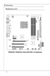
▍ Getting Started Mainboard Layout 785GM-E51/ 760GM-E51 Series (MS-7596 v1.X) Mainboard 1-4
▍ Getting Started Mainboard Layout 785GM-E51/ 760GM-E51 Series (MS-7596 v1.X) Mainboard 1-4

User Guide
Page 14
If you need to purchase accessories and request the part numbers, you purchased. Packing Checklist MS-7596 MSI mainboard MSI Driver/Utility DVD SATA Cable (Optional) Power Cable USB Bracket (Optional) Standard Cable for IDE Devices Back IO Shield User's Guide * The pictures are for reference only and may vary from the packing contents of the product you could search the product web page and find details on our web address http://www.msi.com/index.php 1-5
If you need to purchase accessories and request the part numbers, you purchased. Packing Checklist MS-7596 MSI mainboard MSI Driver/Utility DVD SATA Cable (Optional) Power Cable USB Bracket (Optional) Standard Cable for IDE Devices Back IO Shield User's Guide * The pictures are for reference only and may vary from the packing contents of the product you could search the product web page and find details on our web address http://www.msi.com/index.php 1-5

User Guide
Page 16
Static electricity may damage the components. 2-2-1 Use a grounded wrist strap before handling computer components. For some components, if you with the information about hardware setup procedures. While doing the installation, be careful in the wrong orientation, the components will not work properly. Chapter 2 Hardware Setup This chapter provides you install in holding the components and follow the installation procedures.
Static electricity may damage the components. 2-2-1 Use a grounded wrist strap before handling computer components. For some components, if you with the information about hardware setup procedures. While doing the installation, be careful in the wrong orientation, the components will not work properly. Chapter 2 Hardware Setup This chapter provides you install in holding the components and follow the installation procedures.
User Guide
Page 18
... However, please make sure to install the cooler to prevent overheating. Replacing the CPU While replacing the CPU, always turn off the ATX power supply or unplug the power supply's power cord from overheating. Overclocking This mainboard is not recommended. Any attempt to operate beyond product... specifications. 2-3 For the latest information about CPU, please visit http://www.msi.com/index. Make sure that you are able to tolerate such abnormal setting, while doing overclocking. MS-7596 CPU (Central Processing Unit) When you apply an even layer of CPU.
... However, please make sure to install the cooler to prevent overheating. Replacing the CPU While replacing the CPU, always turn off the ATX power supply or unplug the power supply's power cord from overheating. Overclocking This mainboard is not recommended. Any attempt to operate beyond product... specifications. 2-3 For the latest information about CPU, please visit http://www.msi.com/index. Make sure that you are able to tolerate such abnormal setting, while doing overclocking. MS-7596 CPU (Central Processing Unit) When you apply an even layer of CPU.

User Guide
Page 19
The gold arrow should be seen. Please note that any violation of the correct installation procedures may cause permanent damages to prevent overheating. Meanwhile, do not forget to apply some thermal paste on the top to your CPU & mainboard 1. Make sure to raise the lever up to install the CPU & cooler correctly. The CPU can not be completely embedded into the socket and can only fit in the picture. Wrong installation will cause the damage of the CPU. Press the CPU down firmly into the socket and close the lever with your fingers pressing tightly on top of the CPU to move ...
The gold arrow should be seen. Please note that any violation of the correct installation procedures may cause permanent damages to prevent overheating. Meanwhile, do not forget to apply some thermal paste on the top to your CPU & mainboard 1. Make sure to raise the lever up to install the CPU & cooler correctly. The CPU can not be completely embedded into the socket and can only fit in the picture. Wrong installation will cause the damage of the CPU. Press the CPU down firmly into the socket and close the lever with your fingers pressing tightly on top of the CPU to move ...

User Guide
Page 20
... on the top of your mainboard may vary depending on your fingers, because once the Safety Hook is disconnected from the fixed bolt, it . 7. MS-7596 5. The appearance of the retention mechanism. Locate the Fix Lever and lift up it is necessary to fasten the cooling set onto the retention mechanism.
... on the top of your mainboard may vary depending on your fingers, because once the Safety Hook is disconnected from the fixed bolt, it . 7. MS-7596 5. The appearance of the retention mechanism. Locate the Fix Lever and lift up it is necessary to fasten the cooling set onto the retention mechanism.

User Guide
Page 21
... into the DIMM1 first. • Due to the chipset resource deployment, the system density will only be detected up to 15+GB (not full 16GB) when each DIMM is installed with DDR2 and the DDR3 standard is not backwards compatible. For more information on compatible components, please visit http://www....msi.com/index.php?func=testreport DDR3 240-pin, 1.5V 72x2=144 pin 48x2=96 pin Dual-Channel mode Population Rule In Dual-Channel mode, ...
... into the DIMM1 first. • Due to the chipset resource deployment, the system density will only be detected up to 15+GB (not full 16GB) when each DIMM is installed with DDR2 and the DDR3 standard is not backwards compatible. For more information on compatible components, please visit http://www....msi.com/index.php?func=testreport DDR3 240-pin, 1.5V 72x2=144 pin 48x2=96 pin Dual-Channel mode Population Rule In Dual-Channel mode, ...

User Guide
Page 22
The plastic clip at the sides. Important You can barely see the golden finger if the memory module is properly seated. 3. MS-7596 Installing Memory Modules 1. The memory module has only one notch on the memory module is deeply inserted in the right orientation. 2. Insert the memory module ...
The plastic clip at the sides. Important You can barely see the golden finger if the memory module is properly seated. 3. MS-7596 Installing Memory Modules 1. The memory module has only one notch on the memory module is deeply inserted in the right orientation. 2. Insert the memory module ...

User Guide
Page 23
...-pin power supply, make sure the plug of the power supply is inserted in the proper orientation and the pins are connected to proper ATX power supplies to ensure stable operation of the mainboard. • Power supply of 350 watts (and above) is used to provide power to the CPU. 2.... • Make sure that all the connectors are aligned. If you'd like . ▍ Hardware Setup Power Supply ATX 24-pin Power Connector: JPWR1 This connector allows you like to use the 20-pin ATX power supply as you to the image at the right hand). 1.+23.+3.33.G4V.3.r+5Vo.5uG6Vn.r7+do...
...-pin power supply, make sure the plug of the power supply is inserted in the proper orientation and the pins are connected to proper ATX power supplies to ensure stable operation of the mainboard. • Power supply of 350 watts (and above) is used to provide power to the CPU. 2.... • Make sure that all the connectors are aligned. If you'd like . ▍ Hardware Setup Power Supply ATX 24-pin Power Connector: JPWR1 This connector allows you like to use the 20-pin ATX power supply as you to the image at the right hand). 1.+23.+3.33.G4V.3.r+5Vo.5uG6Vn.r7+do...

User Guide
Page 24
Back Panel MS-7596 VGA Port Mouse/Keyboard DVI-D Port USB Port LAN USB Port USB Port HDMI Port E-SATA Port USB Port Line-In RS-Out Line-Out ...
Back Panel MS-7596 VGA Port Mouse/Keyboard DVI-D Port USB Port LAN USB Port USB Port HDMI Port E-SATA Port USB Port Line-In RS-Out Line-Out ...

User Guide
Page 25
You can connect a network cable to the color of audio jacks. ■ Line-In (Blue) - It is easy to differentiate between audio effects according to it. Side-Surround Out 7.1 channel mode. 2-10 Green/ Orange LED Left Right Color Yellow Green Orange LED State Off On(Steady state) On(brighter & pulsing) Off On On Condition LAN link is established. Center/ Subwoofer Out in 4/ 5.1/ 7.1 channel mode. ■ CS-Out (Orange) - The computer is communicating with another computer on the LAN. 10 Mbits/sec data rate is selected. 100 Mbits/sec data rate is selected. 1000 Mbits/sec...
You can connect a network cable to the color of audio jacks. ■ Line-In (Blue) - It is easy to differentiate between audio effects according to it. Side-Surround Out 7.1 channel mode. 2-10 Green/ Orange LED Left Right Color Yellow Green Orange LED State Off On(Steady state) On(brighter & pulsing) Off On On Condition LAN link is established. Center/ Subwoofer Out in 4/ 5.1/ 7.1 channel mode. ■ CS-Out (Orange) - The computer is communicating with another computer on the LAN. 10 Mbits/sec data rate is selected. 100 Mbits/sec data rate is selected. 1000 Mbits/sec...
