User Guide
Page 2
... Technical Support If a problem arises with your system and no guarantee is a registered trademark of purchase or local distributor. Revision History Revision V1.2 Revision History Update from the user's manual, please contact your place of Novell, Inc. Alternatively, please try the following help resources for further guidance. ◙ Visit the MSI website for FAQ, technical guide, BIOS updates, driver updates, and...
... Technical Support If a problem arises with your system and no guarantee is a registered trademark of purchase or local distributor. Revision History Revision V1.2 Revision History Update from the user's manual, please contact your place of Novell, Inc. Alternatively, please try the following help resources for further guidance. ◙ Visit the MSI website for FAQ, technical guide, BIOS updates, driver updates, and...

User Guide
Page 8
... Started 1-1 Mainboard Specifications 1-2 Mainboard Layout 1-4 Packing Checklist 1-5 Chapter 2 Hardware Setup 2-1 Quick Components Guide 2-2 CPU (Central Processing Unit 2-3 Memory 2-6 Power Supply 2-8 Back Panel 2-9 Connectors 2-11 Jumpers 2-19 Switch 2-20 Slots 2-21 LED Status Indicators 2-24 Chapter 3 BIOS Setup 3-1 Entering Setup 3-2 The Main Menu 3-4 Standard CMOS Features 3-6 Advanced BIOS Features 3-9 Integrated Peripherals 3-12 Power Management Setup 3-14 H/W Monitor 3-16 BIOS Setting Password 3-17 Cell Menu 3-18 M-Flash 3-23 Load Fail-Safe/ Optimized Defaults...
... Started 1-1 Mainboard Specifications 1-2 Mainboard Layout 1-4 Packing Checklist 1-5 Chapter 2 Hardware Setup 2-1 Quick Components Guide 2-2 CPU (Central Processing Unit 2-3 Memory 2-6 Power Supply 2-8 Back Panel 2-9 Connectors 2-11 Jumpers 2-19 Switch 2-20 Slots 2-21 LED Status Indicators 2-24 Chapter 3 BIOS Setup 3-1 Entering Setup 3-2 The Main Menu 3-4 Standard CMOS Features 3-6 Advanced BIOS Features 3-9 Integrated Peripherals 3-12 Power Management Setup 3-14 H/W Monitor 3-16 BIOS Setting Password 3-17 Cell Menu 3-18 M-Flash 3-23 Load Fail-Safe/ Optimized Defaults...
User Guide
Page 11
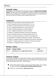
... Audio ■ Chip integrated by Realtek® ALC888S/ ALC889 ■ Flexible 8-channel audio with jack sensing ■ Compliant with Azalia 1.0 Spec IDE ■ 1 IDE port by AMD® SB710 ■ Supports Ultra DMA 66/100/133 mode ■ Supports PIO, Bus Master operation mode SATA ■ 5 SATAII ports by AMD® SB710 ■ 1 E-SATA port by AMD® SB710 ■ Supports storage and data transfers at up to 3 Gb/s 1-2 ▍ Getting Started Mainboard Specifications Processor Support ■ AMD...
... Audio ■ Chip integrated by Realtek® ALC888S/ ALC889 ■ Flexible 8-channel audio with jack sensing ■ Compliant with Azalia 1.0 Spec IDE ■ 1 IDE port by AMD® SB710 ■ Supports Ultra DMA 66/100/133 mode ■ Supports PIO, Bus Master operation mode SATA ■ 5 SATAII ports by AMD® SB710 ■ 1 E-SATA port by AMD® SB710 ■ Supports storage and data transfers at up to 3 Gb/s 1-2 ▍ Getting Started Mainboard Specifications Processor Support ■ AMD...
User Guide
Page 12
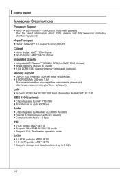
... mouse port - 1 VGA port - 1 DVI-D port - 6 USB 2.0 ports - 1 HDMI port - 1 IEEE 1394 port (optional) - 1 E-SATA port - 1 LAN port - 6 flexible audio ports ■ On-Board - 3 USB 2.0 connectors - 1 IEEE 1394 connector (optional) - 1 Chassis Intrusion connector - 1 Serial port connector - 1 Parallel port connector - 1 CD-In connector - 1 Front Panel Audio connector - 1 SPDIF-out connector - 1 TPM Module connector - 1 Overclock FSB switch Slots ■ 1 PCI Express Gen2 x16 slot ■ 1 PCI Express x1 slot ■ 2 PCI slots, support 3.3V/ 5V PCI bus Interface Form Factor ■ Micro-ATX...
... mouse port - 1 VGA port - 1 DVI-D port - 6 USB 2.0 ports - 1 HDMI port - 1 IEEE 1394 port (optional) - 1 E-SATA port - 1 LAN port - 6 flexible audio ports ■ On-Board - 3 USB 2.0 connectors - 1 IEEE 1394 connector (optional) - 1 Chassis Intrusion connector - 1 Serial port connector - 1 Parallel port connector - 1 CD-In connector - 1 Front Panel Audio connector - 1 SPDIF-out connector - 1 TPM Module connector - 1 Overclock FSB switch Slots ■ 1 PCI Express Gen2 x16 slot ■ 1 PCI Express x1 slot ■ 2 PCI slots, support 3.3V/ 5V PCI bus Interface Form Factor ■ Micro-ATX...
User Guide
Page 23
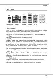
... connector is for digital audio transmission to connect a LCD monitor. Back Panel Optical S/PDIF-out VGA Port Mouse/Keyboard DVI-D Port MS-7596 (optional) 1394 Port USB Port LAN USB Port USB Port HDMI Port E-SATA Port USB Port Line-In CS-Out Line-Out RS-Out Mic SS-Out ▶ Optical S/PDIF-Out This SPDIF (Sony & Philips Digital Interconnect Format) connector is provided for attaching the E-SATA hard drive. 2-9 It provides a high-speed digital interconnection between the computer and its display device...
... connector is for digital audio transmission to connect a LCD monitor. Back Panel Optical S/PDIF-out VGA Port Mouse/Keyboard DVI-D Port MS-7596 (optional) 1394 Port USB Port LAN USB Port USB Port HDMI Port E-SATA Port USB Port Line-In CS-Out Line-Out RS-Out Mic SS-Out ▶ Optical S/PDIF-Out This SPDIF (Sony & Philips Digital Interconnect Format) connector is provided for attaching the E-SATA hard drive. 2-9 It provides a high-speed digital interconnection between the computer and its display device...

User Guide
Page 25
...r i ve Connector 3 1/2" F l oppy D i sk D ri ve Connector IDE Connector: IDE1 This connector supports IDE hard disk drives, optical disk drives and other IDE devices. Fl opMpySDI ...Connector Important If you install two IDE devices on the same cable, you must configure the drives separately to IDE device's documentation supplied by setting jumpers. Refer to master / slave mode by the vendors for jumper setting instructions. 2-11 MS-7596 Connectors Floppy Disk Drive Connector: FDD1 This connector supports 360 KB, 720 KB, 1.2 MB, 1.44 MB or 2.88 MB floppy disk drive...
...r i ve Connector 3 1/2" F l oppy D i sk D ri ve Connector IDE Connector: IDE1 This connector supports IDE hard disk drives, optical disk drives and other IDE devices. Fl opMpySDI ...Connector Important If you install two IDE devices on the same cable, you must configure the drives separately to IDE device's documentation supplied by setting jumpers. Refer to master / slave mode by the vendors for jumper setting instructions. 2-11 MS-7596 Connectors Floppy Disk Drive Connector: FDD1 This connector supports 360 KB, 720 KB, 1.2 MB, 1.44 MB or 2.88 MB floppy disk drive...
User Guide
Page 27
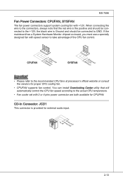
... CPU fan control. If the mainboard has a System Hardware Monitor chipset on-board, you must use a specially designed fan with +12V. You can install Overclocking Center utility that the red wire is provided for external audio input. 4.R3.G2.rG1o.urLonudnd 2-13 MS-7596 Fan Power Connectors: CPUFAN, SYSFAN The fan power connectors support system cooling fan with speed sensor to the +12V; the black wire is Ground and should be connected to the actual CPU temperature...
... CPU fan control. If the mainboard has a System Hardware Monitor chipset on-board, you must use a specially designed fan with +12V. You can install Overclocking Center utility that the red wire is provided for external audio input. 4.R3.G2.rG1o.urLonudnd 2-13 MS-7596 Fan Power Connectors: CPUFAN, SYSFAN The fan power connectors support system cooling fan with speed sensor to the +12V; the black wire is Ground and should be connected to the actual CPU temperature...
User Guide
Page 33
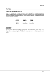
Avoid clearing the CMOS while the system is a CMOS RAM onboard that has a power supply from an external battery to keep the data of system configuration. it is off. With the CMOS RAM, the system can clear CMOS by shorting 2-3 pin while the system is turned on ; If you want to clear the system configuration, set the jumper to 1-2 pin position. Then return to clear data. 1 JBAT1 1 Keep Data 1 Clear Data Important You can automatically boot OS every time it will damage the mainboard. 2-19 MS-7596 Jumpers Clear CMOS Jumper: JBAT1 There is on .
Avoid clearing the CMOS while the system is a CMOS RAM onboard that has a power supply from an external battery to keep the data of system configuration. it is off. With the CMOS RAM, the system can clear CMOS by shorting 2-3 pin while the system is turned on ; If you want to clear the system configuration, set the jumper to 1-2 pin position. Then return to clear data. 1 JBAT1 1 Keep Data 1 Clear Data Important You can automatically boot OS every time it will damage the mainboard. 2-19 MS-7596 Jumpers Clear CMOS Jumper: JBAT1 There is on .
User Guide
Page 35
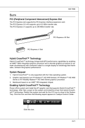
.... Enabling Hybrid CrossFireX™ Technology Power off the system and install the ATI graphic card that Hybrid CrossFireX™ technology. After then, power on an AMD® 785 integrated chipset. Mainboard based on the system and install the driver that supports Hybrid CrossFireX™ technology. PCI Express x16 Slot PCI Express x1 Slot Hybrid CrossFireX™ Technology Hybrid CrossFireX™ technology brings multi-GPU performance capabilities by enabling an AMD® 785G integrated graphics processor and a discrete graphics processor...
.... Enabling Hybrid CrossFireX™ Technology Power off the system and install the ATI graphic card that Hybrid CrossFireX™ technology. After then, power on an AMD® 785 integrated chipset. Mainboard based on the system and install the driver that supports Hybrid CrossFireX™ technology. PCI Express x16 Slot PCI Express x1 Slot Hybrid CrossFireX™ Technology Hybrid CrossFireX™ technology brings multi-GPU performance capabilities by enabling an AMD® 785G integrated graphics processor and a discrete graphics processor...
User Guide
Page 37
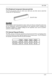
... PCI slot supports LAN card, SCSI card, USB card, and other add-on cards that comply with PCI specifications. 32-bit PCI Slot Important When adding or removing expansion cards, make sure that you unplug the power supply first. The PCI IRQ pins are hardware lines over which devices can send interrupt signals to the PCI bus pins as jumpers, switches or BIOS configuration. PCI Interrupt Request Routing The IRQ, acronym of interrupt request line and pronounced I-R-Q, are typically connected...
... PCI slot supports LAN card, SCSI card, USB card, and other add-on cards that comply with PCI specifications. 32-bit PCI Slot Important When adding or removing expansion cards, make sure that you unplug the power supply first. The PCI IRQ pins are hardware lines over which devices can send interrupt signals to the PCI bus pins as jumpers, switches or BIOS configuration. PCI Interrupt Request Routing The IRQ, acronym of interrupt request line and pronounced I-R-Q, are typically connected...
User Guide
Page 45
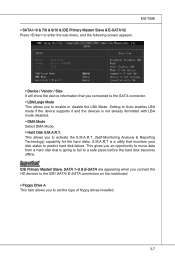
... LBA mode disabled. ▶ DMA Mode Select DMA Mode. ▶ Hard Disk S.M.A.R.T. This allows you to Auto enables LBA mode if the device supports it and the devices is a utility that is going to fail to enable or disable the LBA Mode. Setting to set the type of floppy drives installed. 3-7 Important IDE Primary Master/ Slave, SATA 1~5 & E-SATA are appearing when you connect the HD devices to the IDE/ SATA/ E-SATA connectors on the mainboard. ▶ Floppy Drive A This item allows you to predict hard disk failure.
... LBA mode disabled. ▶ DMA Mode Select DMA Mode. ▶ Hard Disk S.M.A.R.T. This allows you to Auto enables LBA mode if the device supports it and the devices is a utility that is going to fail to enable or disable the LBA Mode. Setting to set the type of floppy drives installed. 3-7 Important IDE Primary Master/ Slave, SATA 1~5 & E-SATA are appearing when you connect the HD devices to the IDE/ SATA/ E-SATA connectors on the mainboard. ▶ Floppy Drive A This item allows you to predict hard disk failure.

User Guide
Page 48
... Programmable Interrupt Controller). Not all processors support Enhanced Halt state (C1E). ▶ SVM Support This item is used to enable/ disable SVM. ▶ Chipset Feature Press to select the MPS version supported by your primary graphics adapter. ▶ PCI Latency Timer This item controls how long each PCI device can to enable it via the various ACPI methods. 3-10 Enabling APIC mode will provide you with PC2001 design guide, the system...
... Programmable Interrupt Controller). Not all processors support Enhanced Halt state (C1E). ▶ SVM Support This item is used to enable/ disable SVM. ▶ Chipset Feature Press to select the MPS version supported by your primary graphics adapter. ▶ PCI Latency Timer This item controls how long each PCI device can to enable it via the various ACPI methods. 3-10 Enabling APIC mode will provide you with PC2001 design guide, the system...
User Guide
Page 50
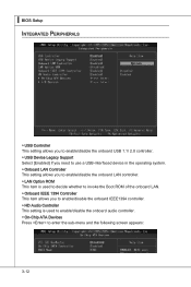
... USB 1.1/ 2.0 controller. ▶ USB Device Legacy Support Select [Enabled] if you need to use a USB-interfaced device in the operating system. ▶ Onboard LAN Controller This setting allows you to enable/disable the onboard LAN controller. ▶ LAN Option ROM This item is used to decide whether to invoke the Boot ROM of the onboard LAN. ▶ Onboard IEEE 1394 Controller This item allows you to enable/disable the onboard IEEE1394 controller. ▶ HD Audio Controller This setting is used to enable/disable the onboard audio controller. ▶ On-Chip ATA Devices Press to enter...
... USB 1.1/ 2.0 controller. ▶ USB Device Legacy Support Select [Enabled] if you need to use a USB-interfaced device in the operating system. ▶ Onboard LAN Controller This setting allows you to enable/disable the onboard LAN controller. ▶ LAN Option ROM This item is used to decide whether to invoke the Boot ROM of the onboard LAN. ▶ Onboard IEEE 1394 Controller This item allows you to enable/disable the onboard IEEE1394 controller. ▶ HD Audio Controller This setting is used to enable/disable the onboard audio controller. ▶ On-Chip ATA Devices Press to enter...
User Guide
Page 51
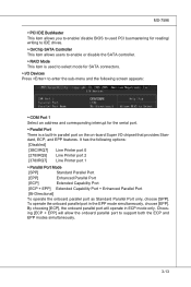
MS-7596 ▶ PCI IDE BusMaster This item allows you to enable/ disable BIOS to used PCI busmastering for reading/ writing to IDE drives. ▶ OnChip SATA Controller This item allows users to enable or disable the SATA controller. ▶ RAID Mode This item is used to select mode for the serial port. ▶ Parallel Port There is a built-in parallel port on the on-board Super I/O chipset that provides Standard, ECP, and EPP features. It has...
MS-7596 ▶ PCI IDE BusMaster This item allows you to enable/ disable BIOS to used PCI busmastering for reading/ writing to IDE drives. ▶ OnChip SATA Controller This item allows users to enable or disable the SATA controller. ▶ RAID Mode This item is used to select mode for the serial port. ▶ Parallel Port There is a built-in parallel port on the on-board Super I/O chipset that provides Standard, ECP, and EPP features. It has...

User Guide
Page 52
... available only when the BIOS supports S3 sleep mode. ▶ ACPI Function This item is saved to main memory that remains powered while most other hardware components turn off to save energy. If your operating system is ACPI-aware, such as Windows 2000/ XP, you can choose to enter the Standby mode in memory will be used to restore the system when a "wake up" event occurs...
... available only when the BIOS supports S3 sleep mode. ▶ ACPI Function This item is saved to main memory that remains powered while most other hardware components turn off to save energy. If your operating system is ACPI-aware, such as Windows 2000/ XP, you can choose to enter the Standby mode in memory will be used to restore the system when a "wake up" event occurs...
User Guide
Page 53
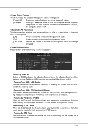
... status before power failure or interrupt occurred. ▶ Wake Up Event Setup Press and the following sub-menu appears. ▶ Wake Up Event By Setting to [BIOS] activates the following fields, and use the following fields to enable or disable the feature of the power button. Settings are : [Power Off] The power button functions as normal power off button. [Suspend] When you press the power button, the computer enters suspend/ sleep mode, but if...
... status before power failure or interrupt occurred. ▶ Wake Up Event Setup Press and the following sub-menu appears. ▶ Wake Up Event By Setting to [BIOS] activates the following fields, and use the following fields to enable or disable the feature of the power button. Settings are : [Power Off] The power button functions as normal power off button. [Suspend] When you press the power button, the computer enters suspend/ sleep mode, but if...
User Guide
Page 54
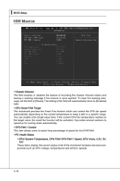
... chassis is once opened. The setting of the field will be activated. ▍ BIOS Setup H/W Monitor ▶ Chassis Intrusion The field enables or disables the feature of the monitored hardware devices/components such as CPU voltage, temperatures and all fans' speeds. 3-16 If the current CPU fan temperature reaches to [Reset]. You can control the CPU fan speed automatically depending on the current temperature to [Enabled] later. ▶ CPU Smart FAN Target The mainboard provides the Smart Fan function which can enable a fan...
... chassis is once opened. The setting of the field will be activated. ▍ BIOS Setup H/W Monitor ▶ Chassis Intrusion The field enables or disables the feature of the monitored hardware devices/components such as CPU voltage, temperatures and all fans' speeds. 3-16 If the current CPU fan temperature reaches to [Reset]. You can control the CPU fan speed automatically depending on the current temperature to [Enabled] later. ▶ CPU Smart FAN Target The mainboard provides the Smart Fan function which can enable a fan...

User Guide
Page 63
... supports FAT/ FAT32 file system drive. ▶ Save File Name as default name. ▶ Start to save file Press "Enter" and select "OK" the system will stare to save the onboard ROM chip data to save BIOS file from When the M-Flash function as Please setup a specific extend name for the BIOS file, which will be saved into the USB drive/ storage drive. Note: we suggest you using [ROM] as Please setup a specific name for the BIOS file...
... supports FAT/ FAT32 file system drive. ▶ Save File Name as default name. ▶ Start to save file Press "Enter" and select "OK" the system will stare to save the onboard ROM chip data to save BIOS file from When the M-Flash function as Please setup a specific extend name for the BIOS file, which will be saved into the USB drive/ storage drive. Note: we suggest you using [ROM] as Please setup a specific name for the BIOS file...

User Guide
Page 94
▍ SB710 RAID Installing the RAID Driver (for 32-bit/ 64-bit version system and then press ENTER. 7. After you complete the RAID BIOS setup, boot from the floppy again after selecting the location to load RAID drive. 5. Press F6 and wait for RAID controller is formatted, and Windows setup starts copying files. Insert the floppy that you can copy the files to a medium (floppy/ CD/ DVD or USB) Important Please follow the instruction below to make a SATA RAID driver for Windows XP: \\ChipSet\AMD\XP...
▍ SB710 RAID Installing the RAID Driver (for 32-bit/ 64-bit version system and then press ENTER. 7. After you complete the RAID BIOS setup, boot from the floppy again after selecting the location to load RAID drive. 5. Press F6 and wait for RAID controller is formatted, and Windows setup starts copying files. Insert the floppy that you can copy the files to a medium (floppy/ CD/ DVD or USB) Important Please follow the instruction below to make a SATA RAID driver for Windows XP: \\ChipSet\AMD\XP...
User Guide
Page 95
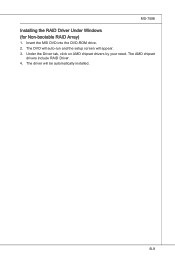
The AMD chipset drivers include RAID Driver. 4. Insert the MSI DVD into the DVD-ROM drive. 2. The driver will appear. 3. MS-7596 Installing the RAID Driver Under Windows (for Non-bootable RAID Array) 1. The DVD will auto-run and the setup screen will be automatically installed. B-9 Under the Driver tab, click on AMD chipset drivers by your need.
The AMD chipset drivers include RAID Driver. 4. Insert the MSI DVD into the DVD-ROM drive. 2. The driver will appear. 3. MS-7596 Installing the RAID Driver Under Windows (for Non-bootable RAID Array) 1. The DVD will auto-run and the setup screen will be automatically installed. B-9 Under the Driver tab, click on AMD chipset drivers by your need.


