
User Guide
Page 8
... Revision History ii Technical Support ii Safety Instructions iii FCC-B Radio Frequency Interference Statement iv WEEE (Waste Electrical and Electronic Equipment) Statement v Chapter 1 Getting Started 1-1 Mainboard Specifications 1-2 Mainboard Layout 1-4 Packing Checklist 1-5 Chapter 2 Hardware Setup 2-1 Quick Components Guide 2-2 CPU (Central Processing Unit 2-3 Memory 2-6 Power Supply 2-8 Back Panel 2-9 Connectors 2-11 Jumpers 2-19 Switch 2-20...
... Revision History ii Technical Support ii Safety Instructions iii FCC-B Radio Frequency Interference Statement iv WEEE (Waste Electrical and Electronic Equipment) Statement v Chapter 1 Getting Started 1-1 Mainboard Specifications 1-2 Mainboard Layout 1-4 Packing Checklist 1-5 Chapter 2 Hardware Setup 2-1 Quick Components Guide 2-2 CPU (Central Processing Unit 2-3 Memory 2-6 Power Supply 2-8 Back Panel 2-9 Connectors 2-11 Jumpers 2-19 Switch 2-20...
User Guide
Page 10
Chapter 1 Getting Started Thank you for optimal system efficiency. Designed to fit the advanced AMD® 64 bits PhenomTM II processor, the 785GM-E65 Series deliver a high performance and professional desktop platform solution. 1-1-1 The 785GM-E65 Series mainboards are based on AMD® 785G & SB710 chipsets for choosing the 785GM-E65 Series (MS7596 v1.X) Micro ATX mainboard.
Chapter 1 Getting Started Thank you for optimal system efficiency. Designed to fit the advanced AMD® 64 bits PhenomTM II processor, the 785GM-E65 Series deliver a high performance and professional desktop platform solution. 1-1-1 The 785GM-E65 Series mainboards are based on AMD® 785G & SB710 chipsets for choosing the 785GM-E65 Series (MS7596 v1.X) Micro ATX mainboard.
User Guide
Page 11
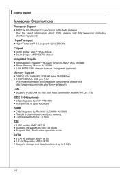
▍ Getting Started Mainboard Specifications Processor Support ■ AMD® 64 bits PhenomTM II processor in the AM3 package. (For the latest information about CPU, please visit http://www.msi.com/index. php?func=cpuform2) HyperTransport ■ HyperTransport™ 3.0, supports up to 2.6 GHz Chipset ■ North ... (total 16 GB Max) ■ 4 DDR3 DIMMs (240-pin/ 1.5V) (For more information on compatible components, please visit http://www.msi.com/index.php?func=testreport) LAN ■ Supports PCIE LAN 10/100/1000 Fast Ethernet by Realtek® RTL8111DL IEEE 1394 (optional) ■...
▍ Getting Started Mainboard Specifications Processor Support ■ AMD® 64 bits PhenomTM II processor in the AM3 package. (For the latest information about CPU, please visit http://www.msi.com/index. php?func=cpuform2) HyperTransport ■ HyperTransport™ 3.0, supports up to 2.6 GHz Chipset ■ North ... (total 16 GB Max) ■ 4 DDR3 DIMMs (240-pin/ 1.5V) (For more information on compatible components, please visit http://www.msi.com/index.php?func=testreport) LAN ■ Supports PCIE LAN 10/100/1000 Fast Ethernet by Realtek® RTL8111DL IEEE 1394 (optional) ■...

User Guide
Page 13
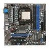
▍ Getting Started Mainboard Layout 785GM-E65 Series (MS-7596 v1.X) Mainboard 1-4
▍ Getting Started Mainboard Layout 785GM-E65 Series (MS-7596 v1.X) Mainboard 1-4

User Guide
Page 14
Packing Checklist MS-7596 MSI mainboard MSI Driver/Utility DVD SATA Cable (Optional) Power Cable USB Bracket (Optional) Standard Cable for IDE Devices Back IO Shield User's Guide * The pictures are for reference only and may vary from the packing contents of the product you could search the product web page and find details on our web address http://www.msi.com/index.php 1-5 If you need to purchase accessories and request the part numbers, you purchased.
Packing Checklist MS-7596 MSI mainboard MSI Driver/Utility DVD SATA Cable (Optional) Power Cable USB Bracket (Optional) Standard Cable for IDE Devices Back IO Shield User's Guide * The pictures are for reference only and may vary from the packing contents of the product you could search the product web page and find details on our web address http://www.msi.com/index.php 1-5 If you need to purchase accessories and request the part numbers, you purchased.

User Guide
Page 17
...your dealer before turning on the computer. Overclocking This mainboard is not recommended. php?func=cpuform2 Important Overheating Overheating will seriously damage the CPU and system. Replacing the CPU While replacing the CPU, always turn off the ATX power supply or unplug the power supply's power cord...by inadequate operation or beyond product specifications is designed to support overclocking. For the latest information about CPU, please visit http://www.msi.com/index. We do not have the CPU cooler, consult your components are installing the CPU, make sure to install the ...
...your dealer before turning on the computer. Overclocking This mainboard is not recommended. php?func=cpuform2 Important Overheating Overheating will seriously damage the CPU and system. Replacing the CPU While replacing the CPU, always turn off the ATX power supply or unplug the power supply's power cord...by inadequate operation or beyond product specifications is designed to support overclocking. For the latest information about CPU, please visit http://www.msi.com/index. We do not have the CPU cooler, consult your components are installing the CPU, make sure to install the ...

User Guide
Page 18
... the lever sideways away from the socket. The CPU can not be seen. Please note that any violation of your mainboard. 4. Wrong installation will cause the damage of the correct installation procedures may cause permanent damages to prevent overheating. If the CPU is correctly installed, the ...
... the lever sideways away from the socket. The CPU can not be seen. Please note that any violation of your mainboard. 4. Wrong installation will cause the damage of the correct installation procedures may cause permanent damages to prevent overheating. If the CPU is correctly installed, the ...

User Guide
Page 19
..., because once the Safety Hook is necessary to fasten the cooling set onto the retention mechanism. Then press down the lever. 8. Important • Mainboard photos shown in this section are for demonstration only. Attach the CPU Fan cable to hook first. 6. Position the cooling set on your... mainboard may vary depending on the model you purchase. • While disconnecting the Safety Hook from the fixed bolt, the fixed lever will spring back ...
..., because once the Safety Hook is necessary to fasten the cooling set onto the retention mechanism. Then press down the lever. 8. Important • Mainboard photos shown in this section are for demonstration only. Attach the CPU Fan cable to hook first. 6. Position the cooling set on your... mainboard may vary depending on the model you purchase. • While disconnecting the Safety Hook from the fixed bolt, the fixed lever will spring back ...

User Guide
Page 22
...: JPWR1 This connector allows you like to use the 20-pin ATX power supply as you to ensure stable operation of the mainboard. • Power supply of the power supply is highly recommended for system stability. 2-8 If you'd like . To connect the ATX 24-pin power supply, make sure the plug of 350...
...: JPWR1 This connector allows you like to use the 20-pin ATX power supply as you to ensure stable operation of the mainboard. • Power supply of the power supply is highly recommended for system stability. 2-8 If you'd like . To connect the ATX 24-pin power supply, make sure the plug of 350...
User Guide
Page 27
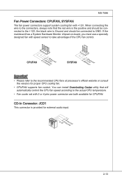
... 4 pins power connector are both available for CPUFAN. the black wire is provided for proper CPU cooling fan. • CPUFAN supports fan control. If the mainboard has a System Hardware Monitor chipset on-board, you must use a specially designed fan with speed sensor to the recommended CPU fans at processor's official website...
... 4 pins power connector are both available for CPUFAN. the black wire is provided for proper CPU cooling fan. • CPUFAN supports fan control. If the mainboard has a System Hardware Monitor chipset on-board, you must use a specially designed fan with speed sensor to the recommended CPU fans at processor's official website...
User Guide
Page 33
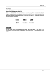
If you want to clear the system configuration, set the jumper to clear data. 1 JBAT1 1 Keep Data 1 Clear Data Important You can automatically boot OS every time it will damage the mainboard. 2-19 Then return to keep the data of system configuration. MS-7596 Jumpers Clear CMOS Jumper: JBAT1 There is off. it is on . With the CMOS RAM, the system can clear CMOS by shorting 2-3 pin while the system is a CMOS RAM onboard that has a power supply from an external battery to 1-2 pin position. Avoid clearing the CMOS while the system is turned on ;
If you want to clear the system configuration, set the jumper to clear data. 1 JBAT1 1 Keep Data 1 Clear Data Important You can automatically boot OS every time it will damage the mainboard. 2-19 Then return to keep the data of system configuration. MS-7596 Jumpers Clear CMOS Jumper: JBAT1 There is off. it is on . With the CMOS RAM, the system can clear CMOS by shorting 2-3 pin while the system is a CMOS RAM onboard that has a power supply from an external battery to 1-2 pin position. Avoid clearing the CMOS while the system is turned on ;

User Guide
Page 34
Follow the instructions below to set the switch to change your mainboard's function through the use of FSB Important • Make sure that you to increase the processor frequency by changing the switch. Please set the FSB. ... set the computer's function. Default Increase 10% speed of FSB Increase 15% speed of FSB Increase 20% speed of switch. ▍ Hardware Setup Switch This mainboard provides the following switch for you power off the system before setting the switch. • When overclocking cause system instability or crash during boot.
Follow the instructions below to set the switch to change your mainboard's function through the use of FSB Important • Make sure that you to increase the processor frequency by changing the switch. Please set the FSB. ... set the computer's function. Default Increase 10% speed of FSB Increase 15% speed of FSB Increase 20% speed of switch. ▍ Hardware Setup Switch This mainboard provides the following switch for you power off the system before setting the switch. • When overclocking cause system instability or crash during boot.
User Guide
Page 35
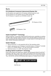
Mainboard based on the system and install the driver that supports Hybrid CrossFireX™ technology. Enabling Hybrid CrossFireX™ Technology Power off the system and install ...
Mainboard based on the system and install the driver that supports Hybrid CrossFireX™ technology. Enabling Hybrid CrossFireX™ Technology Power off the system and install ...

User Guide
Page 43
MS-7596 Load Fail-Safe Defaults Use this menu to load the default values set by the BIOS vendor for stable system performance. ▶ Load Optimized Defaults Use this menu to load the default values set by the mainboard manufacturer specifically for optimal performance of the mainboard. ▶ Save & Exit Setup Save changes to CMOS and exit setup. ▶ Exit Without Saving Abandon all changes and exit setup. 3-5
MS-7596 Load Fail-Safe Defaults Use this menu to load the default values set by the BIOS vendor for stable system performance. ▶ Load Optimized Defaults Use this menu to load the default values set by the mainboard manufacturer specifically for optimal performance of the mainboard. ▶ Save & Exit Setup Save changes to CMOS and exit setup. ▶ Exit Without Saving Abandon all changes and exit setup. 3-5
User Guide
Page 45
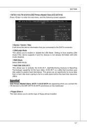
...; Hard Disk S.M.A.R.T. Important IDE Primary Master/ Slave, SATA 1~5 & E-SATA are appearing when you connect the HD devices to the IDE/ SATA/ E-SATA connectors on the mainboard. ▶ Floppy Drive A This item allows you to Auto enables LBA mode if the device supports it and the devices is a utility that is going...
...; Hard Disk S.M.A.R.T. Important IDE Primary Master/ Slave, SATA 1~5 & E-SATA are appearing when you connect the HD devices to the IDE/ SATA/ E-SATA connectors on the mainboard. ▶ Floppy Drive A This item allows you to Auto enables LBA mode if the device supports it and the devices is a utility that is going...
User Guide
Page 54
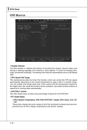
... 1 Control This item allows users to the target value, the smart fan function will automatically return to [Enabled] later. ▶ CPU Smart FAN Target The mainboard provides the Smart Fan function which can enable a fan target value here. If the current CPU fan temperature reaches to select how percentage of speed...
... 1 Control This item allows users to the target value, the smart fan function will automatically return to [Enabled] later. ▶ CPU Smart FAN Target The mainboard provides the Smart Fan function which can enable a fan target value here. If the current CPU fan temperature reaches to select how percentage of speed...

User Guide
Page 64
... performance. The Optimized Defaults are the default values set by the BIOS vendor for optimal performance of the BIOS settings to restore all of the mainboard. When you select Load Optimized Defaults, a message as below appears: Selecting Ok and pressing Enter loads the default factory settings for the most stable, minimal...
... performance. The Optimized Defaults are the default values set by the BIOS vendor for optimal performance of the BIOS settings to restore all of the mainboard. When you select Load Optimized Defaults, a message as below appears: Selecting Ok and pressing Enter loads the default factory settings for the most stable, minimal...

User Guide
Page 86
▍ Realtek Audio ■ 8-Channel Mode for Stereo-Speaker Output 1] Line In 2] Line Out (Front channels) 3] MIC 4] Line Out (Rear channels) 5] Line Out (Center and Subwoofer channel) 6] Line Out (Side channels) Important To enable 7.1 channel audio-out function on Windows Vista operating system, you have to install the Realtek Audio Driver. Or, the mainboard will support 5.1 channel audio-out only. A-22
▍ Realtek Audio ■ 8-Channel Mode for Stereo-Speaker Output 1] Line In 2] Line Out (Front channels) 3] MIC 4] Line Out (Rear channels) 5] Line Out (Center and Subwoofer channel) 6] Line Out (Side channels) Important To enable 7.1 channel audio-out function on Windows Vista operating system, you have to install the Realtek Audio Driver. Or, the mainboard will support 5.1 channel audio-out only. A-22

User Guide
Page 96
DVD-ROM drive for software installation. 3. Operation system: Windows XP or up. 4. Before you install the Overclocking Center, please make sure the system has meet the following requirements: 1. 256MB system memory. 2. DotNet Frame Work 2.0 B-C-1 Appendix C Overclocking Center Overclocking Center, the most useful and powerful utility that MSI has spent much research and efforts to develop, helps users to monitor or configure the hardware status of MSI Mainboard in windows, such as CPU clock, voltage, fan speed and temperature.
DVD-ROM drive for software installation. 3. Operation system: Windows XP or up. 4. Before you install the Overclocking Center, please make sure the system has meet the following requirements: 1. 256MB system memory. 2. DotNet Frame Work 2.0 B-C-1 Appendix C Overclocking Center Overclocking Center, the most useful and powerful utility that MSI has spent much research and efforts to develop, helps users to monitor or configure the hardware status of MSI Mainboard in windows, such as CPU clock, voltage, fan speed and temperature.

User Guide
Page 97
short-cut path in the start-up " menu. You may double-click on the desktop short-cut path in your mainboard, path: Utility --> MSI Utility --> Overclocking Center), it will have your Overclocking Center installed (locate the setup source file in the setup DVD accompanying with your "Start-up menu (path: Start-->Program Files-->MSI-->Overclocking Center->Overclocking Center) C-2 ▍ Overclocking Center Activating Overclocking Center Once you have a short cut icon on the desktop, and a short cut icon on each icon to activate Overclocking Center.
short-cut path in the start-up " menu. You may double-click on the desktop short-cut path in your mainboard, path: Utility --> MSI Utility --> Overclocking Center), it will have your Overclocking Center installed (locate the setup source file in the setup DVD accompanying with your "Start-up menu (path: Start-->Program Files-->MSI-->Overclocking Center->Overclocking Center) C-2 ▍ Overclocking Center Activating Overclocking Center Once you have a short cut icon on the desktop, and a short cut icon on each icon to activate Overclocking Center.


