
User Guide
Page 8
... Supply 2-8 Back Panel 2-9 Connectors 2-11 Jumpers 2-19 Switch 2-20 Slots 2-21 LED Status Indicators 2-24 Chapter 3 BIOS Setup 3-1 Entering Setup 3-2 The Main Menu 3-4 Standard CMOS Features 3-6 Advanced BIOS Features 3-9 Integrated Peripherals 3-12 Power Management Setup 3-14 H/W Monitor 3-16 BIOS Setting Password 3-17 Cell Menu 3-18 M-Flash 3-23 Load Fail-Safe/ Optimized Defaults 3-26 viii
... Supply 2-8 Back Panel 2-9 Connectors 2-11 Jumpers 2-19 Switch 2-20 Slots 2-21 LED Status Indicators 2-24 Chapter 3 BIOS Setup 3-1 Entering Setup 3-2 The Main Menu 3-4 Standard CMOS Features 3-6 Advanced BIOS Features 3-9 Integrated Peripherals 3-12 Power Management Setup 3-14 H/W Monitor 3-16 BIOS Setting Password 3-17 Cell Menu 3-18 M-Flash 3-23 Load Fail-Safe/ Optimized Defaults 3-26 viii

User Guide
Page 36
...com/us-en/crossfirex_hybrid.aspx Important Changing integrated graphic memory operating mode may cause Hybrid CrossFireX™ fail. From the "Graphics Settings" tree in Catalyst Control Center. 2-22 From the "Graphics Adapter" list, select the graphics card that acts as are ...: • Disable the Hybrid CrossFireX™ in Catalyst Control Center. • Reboot into BIOS. • Select the option in Advanced BIOS Features -> Chipset Feature -> On-Chip VGA. • Save BIOS settings and reboot. • Enable the Hybrid CrossFireX™ in the Catalyst Control Center, click ...
...com/us-en/crossfirex_hybrid.aspx Important Changing integrated graphic memory operating mode may cause Hybrid CrossFireX™ fail. From the "Graphics Settings" tree in Catalyst Control Center. 2-22 From the "Graphics Adapter" list, select the graphics card that acts as are ...: • Disable the Hybrid CrossFireX™ in Catalyst Control Center. • Reboot into BIOS. • Select the option in Advanced BIOS Features -> Chipset Feature -> On-Chip VGA. • Save BIOS settings and reboot. • Enable the Hybrid CrossFireX™ in the Catalyst Control Center, click ...
User Guide
Page 37
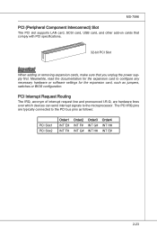
... cards, make sure that you unplug the power supply first. Meanwhile, read the documentation for the expansion card to configure any necessary hardware or software settings for the expansion card, such as follows: PCI Slot1 PCI Slot2 Order1 INT E# INT F# Order2 INT F# INT G# Order3 INT G# INT H# Order4... IRQ pins are hardware lines over which devices can send interrupt signals to the PCI bus pins as jumpers, switches or BIOS configuration. PCI Interrupt Request Routing The IRQ, acronym of interrupt request line and pronounced I-R-Q, are typically connected to the microprocessor.
... cards, make sure that you unplug the power supply first. Meanwhile, read the documentation for the expansion card to configure any necessary hardware or software settings for the expansion card, such as follows: PCI Slot1 PCI Slot2 Order1 INT E# INT F# Order2 INT F# INT G# Order3 INT G# INT H# Order4... IRQ pins are hardware lines over which devices can send interrupt signals to the PCI bus pins as jumpers, switches or BIOS configuration. PCI Interrupt Request Routing The IRQ, acronym of interrupt request line and pronounced I-R-Q, are typically connected to the microprocessor.

User Guide
Page 39
Chapter 3 BIOS Setup This chapter provides information on the screen during the system booting up, and requests you to change the default settings for optimum use. You may need to run the Setup program when: ■ An error message appears on the BIOS Setup program and allows you to run SETUP. ■ You want to configure the system for customized features. 2-3-1
Chapter 3 BIOS Setup This chapter provides information on the screen during the system booting up, and requests you to change the default settings for optimum use. You may need to run the Setup program when: ■ An error message appears on the BIOS Setup program and allows you to run SETUP. ■ You want to configure the system for customized features. 2-3-1

User Guide
Page 42
.... ▶ Power Management Setup Use this menu to specify your settings for power management. ▶ H/W Monitor This entry shows your PC health status. ▶ BIOS Setting Password Use this menu to set the password for BIOS. ▶ Cell Menu Use this menu to specify your settings for frequency/voltage control and overclocking. ▶ M-Flash Use this...
.... ▶ Power Management Setup Use this menu to specify your settings for power management. ▶ H/W Monitor This entry shows your PC health status. ▶ BIOS Setting Password Use this menu to set the password for BIOS. ▶ Cell Menu Use this menu to specify your settings for frequency/voltage control and overclocking. ▶ M-Flash Use this...

User Guide
Page 43
MS-7596 Load Fail-Safe Defaults Use this menu to load the default values set by the BIOS vendor for stable system performance. ▶ Load Optimized Defaults Use this menu to load the default values set by the mainboard manufacturer specifically for optimal performance of the mainboard. ▶ Save & Exit Setup Save changes to CMOS and exit setup. ▶ Exit Without Saving Abandon all changes and exit setup. 3-5
MS-7596 Load Fail-Safe Defaults Use this menu to load the default values set by the BIOS vendor for stable system performance. ▶ Load Optimized Defaults Use this menu to load the default values set by the mainboard manufacturer specifically for optimal performance of the mainboard. ▶ Save & Exit Setup Save changes to CMOS and exit setup. ▶ Exit Without Saving Abandon all changes and exit setup. 3-5

User Guide
Page 44
...BIOS Setup Standard CMOS Features The items in Standard CMOS Features Menu include some basic setup items. Use the arrow keys to highlight the item and then use the or keys to select the value you want in each item. ▶ Date (MM:DD:YY) This allows you to set... the system to Sat, determined by users. ▶ Time (HH:MM:SS) This allows you to set the system time that you want (usually the current date). The format is ...from 1 to 31 can be keyed by numeric function keys. [year] The year can be adjusted by BIOS.
...BIOS Setup Standard CMOS Features The items in Standard CMOS Features Menu include some basic setup items. Use the arrow keys to highlight the item and then use the or keys to select the value you want in each item. ▶ Date (MM:DD:YY) This allows you to set... the system to Sat, determined by users. ▶ Time (HH:MM:SS) This allows you to set the system time that you want (usually the current date). The format is ...from 1 to 31 can be keyed by numeric function keys. [year] The year can be adjusted by BIOS.

User Guide
Page 46
This sub-menu shows the CPU information, BIOS version and memory status of your system (read only). 3-8 When the system stops for any detected error. ▶ System Information Press to enter the sub-menu, and the following screen appears. ▍ BIOS Setup ▶ Hold On The setting determines whether the system will halt on for 15 seconds and then automatically resume its operation. [All Error] The system stops when any error is detected. [No Error] The system does not stop for the errors preset, it will stop if an error is detected at boot.
This sub-menu shows the CPU information, BIOS version and memory status of your system (read only). 3-8 When the system stops for any detected error. ▶ System Information Press to enter the sub-menu, and the following screen appears. ▍ BIOS Setup ▶ Hold On The setting determines whether the system will halt on for 15 seconds and then automatically resume its operation. [All Error] The system stops when any error is detected. [No Error] The system does not stop for the errors preset, it will stop if an error is detected at boot.

User Guide
Page 47
...[Disabled] Shows the POST messages at all times. Setting to [On] will allow users to show the company logo on the boot-up screen. When enabled, the BIOS' data cannot be changed when attempting to update the BIOS. Settings are: [Enabled] Shows a still image (logo)... on the numeric keypad. 3-9 Advanced BIOS Features MS-7596 ▶ BIOS Flash Protection This function protects the BIOS from accidental corruption by unauthorized ...
...[Disabled] Shows the POST messages at all times. Setting to [On] will allow users to show the company logo on the boot-up screen. When enabled, the BIOS' data cannot be changed when attempting to update the BIOS. Settings are: [Enabled] Shows a still image (logo)... on the numeric keypad. 3-9 Advanced BIOS Features MS-7596 ▶ BIOS Flash Protection This function protects the BIOS from accidental corruption by unauthorized ...

User Guide
Page 48
...the operating system. To find out which version to use, consult the vendor of the chipset. For better PCI performance, you should set to enable or disable the APIC (Advanced Programmable Interrupt Controller). You can to enter the sub-menu and the following screen appears: ...allows you with PC2001 design guide, the system is your operating system. ▍ BIOS Setup ▶ IOAPIC Function This field is part of your operating system. ▶ Primary Graphic's Adapter This setting specifies which MPS (Multi-Processor Specification) version to be used to higher values, every...
...the operating system. To find out which version to use, consult the vendor of the chipset. For better PCI performance, you should set to enable or disable the APIC (Advanced Programmable Interrupt Controller). You can to enter the sub-menu and the following screen appears: ...allows you with PC2001 design guide, the system is your operating system. ▍ BIOS Setup ▶ IOAPIC Function This field is part of your operating system. ▶ Primary Graphic's Adapter This setting specifies which MPS (Multi-Processor Specification) version to be used to higher values, every...

User Guide
Page 49
...memory size shared to the VGA card. ▶ SIDEPORT Memory Frequency This item allows you to set the first boot device where BIOS attempts to load the disk operating system. ▶ Boot From Other Device Setting the option to [Yes] allows the system to try to boot from other data blocks in ...Trusted Computing Press to enter the sub-menu and the following screen appears: ▶ Clearing the TPM Press Enter to clear the TPM status. 3-11 Setting to [UMA], allocates the system share memory for onboard VGA. MS-7596 ▶ UMA Location This item is used to select the location of UMA...
...memory size shared to the VGA card. ▶ SIDEPORT Memory Frequency This item allows you to set the first boot device where BIOS attempts to load the disk operating system. ▶ Boot From Other Device Setting the option to [Yes] allows the system to try to boot from other data blocks in ...Trusted Computing Press to enter the sub-menu and the following screen appears: ▶ Clearing the TPM Press Enter to clear the TPM status. 3-11 Setting to [UMA], allocates the system share memory for onboard VGA. MS-7596 ▶ UMA Location This item is used to select the location of UMA...
User Guide
Page 50
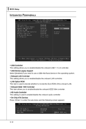
▍ BIOS Setup Integrated Peripherals ▶ USB Controller This setting allows you to enable/disable the onboard USB 1.1/ 2.0 controller. ▶ USB Device Legacy Support Select [Enabled] if you need to use a USB-interfaced device in the operating system. ▶ Onboard LAN Controller This setting allows you to enable/... ▶ Onboard IEEE 1394 Controller This item allows you to enable/disable the onboard IEEE1394 controller. ▶ HD Audio Controller This setting is used to enable/disable the onboard audio controller. ▶ On-Chip ATA Devices Press to enter the sub-menu and the ...
▍ BIOS Setup Integrated Peripherals ▶ USB Controller This setting allows you to enable/disable the onboard USB 1.1/ 2.0 controller. ▶ USB Device Legacy Support Select [Enabled] if you need to use a USB-interfaced device in the operating system. ▶ Onboard LAN Controller This setting allows you to enable/... ▶ Onboard IEEE 1394 Controller This item allows you to enable/disable the onboard IEEE1394 controller. ▶ HD Audio Controller This setting is used to enable/disable the onboard audio controller. ▶ On-Chip ATA Devices Press to enter the sub-menu and the ...

User Guide
Page 52
...aware, such as Windows 2000/ XP, you can choose to enter the Standby mode in S1(POS) or S3(STR) fashion through the setting of system configuration and open applications/files is saved to main memory that remains powered while most other hardware components turn off to save energy...as Windows 98SE/ 2000/ ME/ XP, select [Enabled]. ▶ ACPI Standby State This item specifies the power saving modes for ACPI function. Settings are available only when the BIOS supports S3 sleep mode. ▶ ACPI Function This item is to restore the system when a "wake up" event occurs. 3-14 tem's ...
...aware, such as Windows 2000/ XP, you can choose to enter the Standby mode in S1(POS) or S3(STR) fashion through the setting of system configuration and open applications/files is saved to main memory that remains powered while most other hardware components turn off to save energy...as Windows 98SE/ 2000/ ME/ XP, select [Enabled]. ▶ ACPI Standby State This item specifies the power saving modes for ACPI function. Settings are available only when the BIOS supports S3 sleep mode. ▶ ACPI Function This item is to restore the system when a "wake up" event occurs. 3-14 tem's ...
User Guide
Page 53
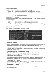
...interrupt occurred. ▶ Wake Up Event Setup Press and the following sub-menu appears. ▶ Wake Up Event By Setting to [BIOS] activates the following fields, and use the following fields to set the wake up the system from S3 (Suspend to RAM) sleep state. ▶ Resume From S3 By PS/2 Keyboard...be awakened from what power saving modes when input signal of the PS/2 keyboard/ mouse is detected. ▶ Resume By PCI Device (PME#) When set to [Enabled], the feature allows your system to be awakened from the power saving modes through any event on PME (Power Management Event). ▶ ...
...interrupt occurred. ▶ Wake Up Event Setup Press and the following sub-menu appears. ▶ Wake Up Event By Setting to [BIOS] activates the following fields, and use the following fields to set the wake up the system from S3 (Suspend to RAM) sleep state. ▶ Resume From S3 By PS/2 Keyboard...be awakened from what power saving modes when input signal of the PS/2 keyboard/ mouse is detected. ▶ Resume By PCI Device (PME#) When set to [Enabled], the feature allows your system to be awakened from the power saving modes through any event on PME (Power Management Event). ▶ ...
User Guide
Page 54
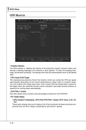
...field will be activated. You can control the CPU fan speed automatically depending on the current temperature to [Reset]. To clear the warning message, set the field to keep it with in a specific range. It provides several sections to speed up for cooling down automatically. ▶ SYS ... the current status of all of recording the chassis intrusion status and issuing a warning message if the chassis is once opened. ▍ BIOS Setup H/W Monitor ▶ Chassis Intrusion The field enables or disables the feature of the monitored hardware devices/components such as CPU voltage, ...
...field will be activated. You can control the CPU fan speed automatically depending on the current temperature to [Reset]. To clear the warning message, set the field to keep it with in a specific range. It provides several sections to speed up for cooling down automatically. ▶ SYS ... the current status of all of recording the chassis intrusion status and issuing a warning message if the chassis is once opened. ▍ BIOS Setup H/W Monitor ▶ Chassis Intrusion The field enables or disables the feature of the monitored hardware devices/components such as CPU voltage, ...

User Guide
Page 55
Retype the password and press . MS-7596 BIOS Setting Password When you select this function, a message as below will appear on the screen: Type the password, up confirming the password will boot and you ... will be prompted to confirm the password. The password typed now will replace any previously set password from changing any password. To clear a set , you try to abort the selection and not enter a password. When a password has been set password, just press when you are prompted to six characters in length, and press...
Retype the password and press . MS-7596 BIOS Setting Password When you select this function, a message as below will appear on the screen: Type the password, up confirming the password will boot and you ... will be prompted to confirm the password. The password typed now will replace any previously set password from changing any password. To clear a set , you try to abort the selection and not enter a password. When a password has been set password, just press when you are prompted to six characters in length, and press...

User Guide
Page 56
▍ BIOS Setup Cell Menu Important Change these settings only if you are familiar with the chipset. ▶ Current CPU / DRAM Frequency These items show the current clocks of installed CPU. 3-18 Read-only. ▶ CPU Specifications Press to enter the sub-menu and the following screen appears. This submenu shows the information of CPU and Memory speed.
▍ BIOS Setup Cell Menu Important Change these settings only if you are familiar with the chipset. ▶ Current CPU / DRAM Frequency These items show the current clocks of installed CPU. 3-18 Read-only. ▶ CPU Specifications Press to enter the sub-menu and the following screen appears. This submenu shows the information of CPU and Memory speed.

User Guide
Page 57
...Power Options Properties tag, and select Minimal Power Management under Power schemes. 3-19 This submenu shows the technologies that : • Run BIOS Setup, and select Cell Menu. Important To ensure that Cool'n'Quiet function is activated and will be working properly, it is required to ... lower CPU speed and power consumption. MS-7596 ▶ CPU Technology Support Press to "Enabled". • Enter Windows, and select [Start]->[Settings]>[Control Panel]->[Power Options]. Under Cell Menu, find AMD Cool'n'Quiet, and set this item to enter the sub-menu and the following screen appears.
...Power Options Properties tag, and select Minimal Power Management under Power schemes. 3-19 This submenu shows the technologies that : • Run BIOS Setup, and select Cell Menu. Important To ensure that Cool'n'Quiet function is activated and will be working properly, it is required to ... lower CPU speed and power consumption. MS-7596 ▶ CPU Technology Support Press to "Enabled". • Enter Windows, and select [Start]->[Settings]>[Control Panel]->[Power Options]. Under Cell Menu, find AMD Cool'n'Quiet, and set this item to enter the sub-menu and the following screen appears.

User Guide
Page 58
It is for overclock. This submenu displays the information of installed memory. 3-20 Setting to [Enabled] allows you to select the CPU Front Side Bus clock frequency (in MHz). ▶ Adjust CPU Ratio This item is used to adjust ... is used to adjust CPU-NB ratio. ▶ Adjusted CPU Frequency (MHz) It shows the adjusted CPU frequency. ▍ BIOS Setup ▶ Adjust CPU FSB Frequency (MHz) This item allows you to set the CPU Ratio higher. It is available only when the processor supports this function. ▶ Memory-Z Press to enter...
It is for overclock. This submenu displays the information of installed memory. 3-20 Setting to [Enabled] allows you to select the CPU Front Side Bus clock frequency (in MHz). ▶ Adjust CPU Ratio This item is used to adjust ... is used to adjust CPU-NB ratio. ▶ Adjusted CPU Frequency (MHz) It shows the adjusted CPU frequency. ▍ BIOS Setup ▶ Adjust CPU FSB Frequency (MHz) This item allows you to set the CPU Ratio higher. It is available only when the processor supports this function. ▶ Memory-Z Press to enter...

User Guide
Page 64
.... When you select Load Fail-Safe Defaults, a message as below appears: Selecting Ok and pressing Enter loads the BIOS default values for optimal performance of the BIOS settings to restore all of the mainboard. ▍ BIOS Setup Load Fail-Safe/ Optimized Defaults The two options on the main menu allow users to the default...
.... When you select Load Fail-Safe Defaults, a message as below appears: Selecting Ok and pressing Enter loads the BIOS default values for optimal performance of the BIOS settings to restore all of the mainboard. ▍ BIOS Setup Load Fail-Safe/ Optimized Defaults The two options on the main menu allow users to the default...

