
User Guide
Page 8
... Interference Statement iv WEEE (Waste Electrical and Electronic Equipment) Statement v Chapter 1 Getting Started 1-1 Mainboard Specifications 1-2 Mainboard Layout 1-4 Packing Checklist 1-5 Chapter 2 Hardware Setup 2-1 Quick Components Guide 2-2 CPU (Central Processing Unit 2-3 Memory 2-6 Power Supply 2-8 Back Panel 2-9 Connectors 2-11 Jumpers 2-19 Switch 2-20 Slots 2-21 LED Status Indicators 2-24 Chapter 3 BIOS Setup 3-1 Entering Setup...
... Interference Statement iv WEEE (Waste Electrical and Electronic Equipment) Statement v Chapter 1 Getting Started 1-1 Mainboard Specifications 1-2 Mainboard Layout 1-4 Packing Checklist 1-5 Chapter 2 Hardware Setup 2-1 Quick Components Guide 2-2 CPU (Central Processing Unit 2-3 Memory 2-6 Power Supply 2-8 Back Panel 2-9 Connectors 2-11 Jumpers 2-19 Switch 2-20 Slots 2-21 LED Status Indicators 2-24 Chapter 3 BIOS Setup 3-1 Entering Setup...
User Guide
Page 11
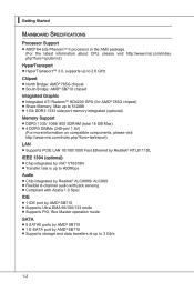
...Started Mainboard Specifications Processor Support ■ AMD® 64 bits PhenomTM II processor in the AM3 package. (For the latest information about CPU, please visit http://www.msi.com/index. php?func=cpuform2) HyperTransport ■ HyperTransport™ 3.0, supports up to 2.6 GHz Chipset ■ North Bridge: AMD&#... (total 16 GB Max) ■ 4 DDR3 DIMMs (240-pin/ 1.5V) (For more information on compatible components, please visit http://www.msi.com/index.php?func=testreport) LAN ■ Supports PCIE LAN 10/100/1000 Fast Ethernet by Realtek® RTL8111DL IEEE 1394 (optional) ■...
...Started Mainboard Specifications Processor Support ■ AMD® 64 bits PhenomTM II processor in the AM3 package. (For the latest information about CPU, please visit http://www.msi.com/index. php?func=cpuform2) HyperTransport ■ HyperTransport™ 3.0, supports up to 2.6 GHz Chipset ■ North Bridge: AMD&#... (total 16 GB Max) ■ 4 DDR3 DIMMs (240-pin/ 1.5V) (For more information on compatible components, please visit http://www.msi.com/index.php?func=testreport) LAN ■ Supports PCIE LAN 10/100/1000 Fast Ethernet by Realtek® RTL8111DL IEEE 1394 (optional) ■...

User Guide
Page 17
...dissipation. Make sure that you are able to operate beyond product specifications. 2-3 For the latest information about CPU, please visit http://www.msi.com/index. Any attempt to tolerate such abnormal setting, while doing overclocking. Overclocking This mainboard is not recommended.... Replacing the CPU While replacing the CPU, always turn off the ATX power supply or unplug the power supply's power cord from overheating...
...dissipation. Make sure that you are able to operate beyond product specifications. 2-3 For the latest information about CPU, please visit http://www.msi.com/index. Any attempt to tolerate such abnormal setting, while doing overclocking. Overclocking This mainboard is not recommended.... Replacing the CPU While replacing the CPU, always turn off the ATX power supply or unplug the power supply's power cord from overheating...

User Guide
Page 18
... the socket and close the lever. ▍ Hardware Setup CPU & Cooler Installation When you are installing the CPU, make sure the CPU is being closed, always close the lever with your fingers pressing tightly on top of the CPU. The CPU can not be completely embedded into the socket and can only...Make sure to raise the lever up to apply some thermal paste on CPU before installing the heat sink/cooler fan for the gold arrow of the CPU to your CPU & mainboard 1. The gold arrow should be seen. Press the CPU down firmly into the socket. 2-4 Meanwhile, do not forget to a ...
... the socket and close the lever. ▍ Hardware Setup CPU & Cooler Installation When you are installing the CPU, make sure the CPU is being closed, always close the lever with your fingers pressing tightly on top of the CPU. The CPU can not be completely embedded into the socket and can only...Make sure to raise the lever up to apply some thermal paste on CPU before installing the heat sink/cooler fan for the gold arrow of the CPU to your CPU & mainboard 1. The gold arrow should be seen. Press the CPU down firmly into the socket. 2-4 Meanwhile, do not forget to a ...

User Guide
Page 19
Locate the Fix Lever and lift up it is necessary to the CPU fan connector on your fingers, because once the Safety Hook is disconnected from the fixed bolt, the fixed lever will spring back instantly. 2-5 Hook one ...end of your mainboard may vary depending on the model you purchase. • While disconnecting the Safety Hook from the fixed bolt, it . 7. Attach the CPU Fan cable to keep an eye on the mainboard. Position the cooling set on the top of the clip to hook first. 6. Fasten down the...
Locate the Fix Lever and lift up it is necessary to the CPU fan connector on your fingers, because once the Safety Hook is disconnected from the fixed bolt, the fixed lever will spring back instantly. 2-5 Hook one ...end of your mainboard may vary depending on the model you purchase. • While disconnecting the Safety Hook from the fixed bolt, it . 7. Attach the CPU Fan cable to keep an eye on the mainboard. Position the cooling set on the top of the clip to hook first. 6. Fasten down the...

User Guide
Page 22
...+O1B.1+K2211.V+3213.V+4.133.-5V.113.2G6V1V.rP7o1.SuG81-n.rO9Gdo2.NurG0o2n#.ruR1do2n.eu+2ds2n5.+3dV2.5+4V5.GVround ATX 4-pin Power Connector: JPWR2 This connector is used to provide power to the CPU. 2.G1.rGouronudnd 4.+31.+21V2V Important • Make sure that all the connectors are aligned.... ▍ Hardware Setup Power Supply ATX 24-pin Power Connector: JPWR1 This connector allows you to ensure stable operation ...
...+O1B.1+K2211.V+3213.V+4.133.-5V.113.2G6V1V.rP7o1.SuG81-n.rO9Gdo2.NurG0o2n#.ruR1do2n.eu+2ds2n5.+3dV2.5+4V5.GVround ATX 4-pin Power Connector: JPWR2 This connector is used to provide power to the CPU. 2.G1.rGouronudnd 4.+31.+21V2V Important • Make sure that all the connectors are aligned.... ▍ Hardware Setup Power Supply ATX 24-pin Power Connector: JPWR1 This connector allows you to ensure stable operation ...
User Guide
Page 27
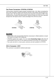
CPUFAN 4.3C.oS2n.e+1tnr.1osG2lorVround SYSFAN 3.S2.e+1n1.sG2orVround Important • Please refer to the recommended CPU fans at processor's official website or consult the vendors for external audio input. 4.R3.G2.rG1o.urLonudnd 2-13 MS-7596 Fan Power ... When connecting the wire to the connectors, always note that will automatically control the CPU fan speed according to take advantage of the CPU fan control. CD-In Connector: JCD1 This connector is provided for proper CPU cooling fan. • CPUFAN supports fan control. You can install Overclocking Center utility...
CPUFAN 4.3C.oS2n.e+1tnr.1osG2lorVround SYSFAN 3.S2.e+1n1.sG2orVround Important • Please refer to the recommended CPU fans at processor's official website or consult the vendors for external audio input. 4.R3.G2.rG1o.urLonudnd 2-13 MS-7596 Fan Power ... When connecting the wire to the connectors, always note that will automatically control the CPU fan speed according to take advantage of the CPU fan control. CD-In Connector: JCD1 This connector is provided for proper CPU cooling fan. • CPUFAN supports fan control. You can install Overclocking Center utility...

User Guide
Page 38
CPU is in 4 phase power mode. 2-24 ▍ Hardware Setup LED Status Indicators CPU Phase LEDs: LED1, LED2, LED3, LED4 These LEDs indicate the current CPU power phase mode. Blue light Off LED1 LED2 LED3 LED4 Mode CPU is in 1 phase power mode. Follow the instructions below to read.
CPU is in 4 phase power mode. 2-24 ▍ Hardware Setup LED Status Indicators CPU Phase LEDs: LED1, LED2, LED3, LED4 These LEDs indicate the current CPU power phase mode. Blue light Off LED1 LED2 LED3 LED4 Mode CPU is in 1 phase power mode. Follow the instructions below to read.

User Guide
Page 46
This sub-menu shows the CPU information, BIOS version and memory status of your system (read only). 3-8 ▍ BIOS Setup ▶ Hold On The setting determines whether the system will halt on for any detected error. ▶ System Information Press to enter the sub-menu, and the following screen appears. When the system stops for the errors preset, it will stop if an error is detected. [No Error] The system does not stop for 15 seconds and then automatically resume its operation. [All Error] The system stops when any error is detected at boot.
This sub-menu shows the CPU information, BIOS version and memory status of your system (read only). 3-8 ▍ BIOS Setup ▶ Hold On The setting determines whether the system will halt on for any detected error. ▶ System Information Press to enter the sub-menu, and the following screen appears. When the system stops for the errors preset, it will stop if an error is detected. [No Error] The system does not stop for 15 seconds and then automatically resume its operation. [All Error] The system stops when any error is detected at boot.

User Guide
Page 48
...the chipset. When set to higher values, every PCI device can to enable it via the various ACPI methods. 3-10 You need to read the CPU power consumption while idle. Enabling APIC mode will provide you with PC2001 design guide, the system is your operating system. ▶ Primary Graphic's ... bandwidth. You can conduct transactions for the system. ▶ MPS Table Version This field allows you should set the item to higher values. ▶ CPU Feature Press to enter the sub-menu and the following screen appears: ▶ HPET The HPET (High Precision Event Timers) is a component that is...
...the chipset. When set to higher values, every PCI device can to enable it via the various ACPI methods. 3-10 You need to read the CPU power consumption while idle. Enabling APIC mode will provide you with PC2001 design guide, the system is your operating system. ▶ Primary Graphic's ... bandwidth. You can conduct transactions for the system. ▶ MPS Table Version This field allows you should set the item to higher values. ▶ CPU Feature Press to enter the sub-menu and the following screen appears: ▶ HPET The HPET (High Precision Event Timers) is a component that is...

User Guide
Page 52
...'s context. [S3] The S3 sleep mode is a lower power state where the in formation of this field. In this state, no system context is lost (CPU or chipset) and hardware maintains all sys- The information stored in memory will be used to save energy. If your operating system supports ACPI, such...
...'s context. [S3] The S3 sleep mode is a lower power state where the in formation of this field. In this state, no system context is lost (CPU or chipset) and hardware maintains all sys- The information stored in memory will be used to save energy. If your operating system supports ACPI, such...
User Guide
Page 54
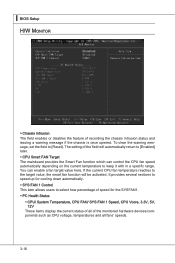
... mainboard provides the Smart Fan function which can enable a fan target value here. The setting of the monitored hardware devices/components such as CPU voltage, temperatures and all of the field will be activated. It provides several sections to speed up for the SYSFAN1. ▶ PC Health... Status ▶ CPU/ System Temperature, CPU FAN/ SYS FAN 1 Speed, CPU Vcore, 3.3V, 5V, 12V These items display the current status of all fans' speeds. 3-16 You can control the CPU fan speed automatically depending on the current temperature to keep it with...
... mainboard provides the Smart Fan function which can enable a fan target value here. The setting of the monitored hardware devices/components such as CPU voltage, temperatures and all of the field will be activated. It provides several sections to speed up for the SYSFAN1. ▶ PC Health... Status ▶ CPU/ System Temperature, CPU FAN/ SYS FAN 1 Speed, CPU Vcore, 3.3V, 5V, 12V These items display the current status of all fans' speeds. 3-16 You can control the CPU fan speed automatically depending on the current temperature to keep it with...

User Guide
Page 56
▍ BIOS Setup Cell Menu Important Change these settings only if you are familiar with the chipset. ▶ Current CPU / DRAM Frequency These items show the current clocks of installed CPU. 3-18 This submenu shows the information of CPU and Memory speed. Read-only. ▶ CPU Specifications Press to enter the sub-menu and the following screen appears.
▍ BIOS Setup Cell Menu Important Change these settings only if you are familiar with the chipset. ▶ Current CPU / DRAM Frequency These items show the current clocks of installed CPU. 3-18 This submenu shows the information of CPU and Memory speed. Read-only. ▶ CPU Specifications Press to enter the sub-menu and the following screen appears.

User Guide
Page 57
...; Enter Windows, and select [Start]->[Settings]>[Control Panel]->[Power Options]. Important To ensure that the installed CPU supported. ▶ AMD Cool'n'Quiet The Cool'n'Quiet technology can effectively and dynamically lower CPU speed and power consumption. MS-7596 ▶ CPU Technology Support Press to enter the sub-menu and the following screen appears.
...; Enter Windows, and select [Start]->[Settings]>[Control Panel]->[Power Options]. Important To ensure that the installed CPU supported. ▶ AMD Cool'n'Quiet The Cool'n'Quiet technology can effectively and dynamically lower CPU speed and power consumption. MS-7596 ▶ CPU Technology Support Press to enter the sub-menu and the following screen appears.

User Guide
Page 58
... to enter the sub-menu and the following screen appears. Setting to [Enabled] allows you to select the CPU Front Side Bus clock frequency (in MHz). ▶ Adjust CPU Ratio This item is for overclock. This submenu displays the information of installed memory. 3-20 Read-only. ▶...; Advanced Clock Calibration This item is used to adjust CPU-NB ratio. ▶ Adjusted CPU Frequency (MHz) It shows the adjusted CPU frequency. ▍ BIOS Setup ▶ Adjust CPU FSB Frequency (MHz) This item allows you to set the...
... to enter the sub-menu and the following screen appears. Setting to [Enabled] allows you to select the CPU Front Side Bus clock frequency (in MHz). ▶ Adjust CPU Ratio This item is for overclock. This submenu displays the information of installed memory. 3-20 Read-only. ▶...; Advanced Clock Calibration This item is used to adjust CPU-NB ratio. ▶ Adjusted CPU Frequency (MHz) It shows the adjusted CPU frequency. ▍ BIOS Setup ▶ Adjust CPU FSB Frequency (MHz) This item allows you to set the...

User Guide
Page 60
... overclock the onboard VGA. ▶ Onboard VGA Clock This item will appear when Onboard VGA Over Clock sets to adjust the voltage of CPU, Memory and chipset. 3-22 Read-only. ▶ Onboard VGA Over Clock This item allows you to select the PCIE frequency (in MHz...[Auto], the system will remove (turn off) clocks from empty DRAM/ PCI slots to minimize the electromagnetic interference (EMI). ▶ CPU VDD Voltage (V)/ CPU-NB VDD Voltage (V)/ CPU Voltage (V)/ CPU-NB Voltage (V)/ DRAM Voltage (V)/ SB Voltage (V)/ NB Voltage (V)/ HT Link Voltage (V) These items are used to [Enabled]. It ...
... overclock the onboard VGA. ▶ Onboard VGA Clock This item will appear when Onboard VGA Over Clock sets to adjust the voltage of CPU, Memory and chipset. 3-22 Read-only. ▶ Onboard VGA Over Clock This item allows you to select the PCIE frequency (in MHz...[Auto], the system will remove (turn off) clocks from empty DRAM/ PCI slots to minimize the electromagnetic interference (EMI). ▶ CPU VDD Voltage (V)/ CPU-NB VDD Voltage (V)/ CPU Voltage (V)/ CPU-NB Voltage (V)/ DRAM Voltage (V)/ SB Voltage (V)/ NB Voltage (V)/ HT Link Voltage (V) These items are used to [Enabled]. It ...

User Guide
Page 96
Before you install the Overclocking Center, please make sure the system has meet the following requirements: 1. 256MB system memory. 2. Operation system: Windows XP or up. 4. Appendix C Overclocking Center Overclocking Center, the most useful and powerful utility that MSI has spent much research and efforts to develop, helps users to monitor or configure the hardware status of MSI Mainboard in windows, such as CPU clock, voltage, fan speed and temperature. DotNet Frame Work 2.0 B-C-1 DVD-ROM drive for software installation. 3.
Before you install the Overclocking Center, please make sure the system has meet the following requirements: 1. 256MB system memory. 2. Operation system: Windows XP or up. 4. Appendix C Overclocking Center Overclocking Center, the most useful and powerful utility that MSI has spent much research and efforts to develop, helps users to monitor or configure the hardware status of MSI Mainboard in windows, such as CPU clock, voltage, fan speed and temperature. DotNet Frame Work 2.0 B-C-1 DVD-ROM drive for software installation. 3.

User Guide
Page 98
Important The pictures in this appendix are for detailed information. Motherboard Click Motherboard to the appearance of your system for reference only and may vary from the product you can read the information of motherboard, BIOS, installed CPU and installed graphics card. C-3 MS-7596 System Info In the System Info screen, you purchased. Please refer to read the information of motherboard/ memory/ PCI.
Important The pictures in this appendix are for detailed information. Motherboard Click Motherboard to the appearance of your system for reference only and may vary from the product you can read the information of motherboard, BIOS, installed CPU and installed graphics card. C-3 MS-7596 System Info In the System Info screen, you purchased. Please refer to read the information of motherboard/ memory/ PCI.
User Guide
Page 102
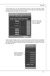
...-down menu will popup a warning message to warning you when the temperature/ fan speed is over/ lower the values you set the maximum CPU/ system temperature and the minimum CPU/ system fan speed by using the scroll bar. The system will appear. In the "System Warning" block, you can select desired values...
...-down menu will popup a warning message to warning you when the temperature/ fan speed is over/ lower the values you set the maximum CPU/ system temperature and the minimum CPU/ system fan speed by using the scroll bar. The system will appear. In the "System Warning" block, you can select desired values...


