User Guide
Page 2
... for further guidance. ◙ Visit the MSI website for FAQ, technical guide, BIOS updates, driver updates, and other information: http://www.msi.com/index.php?func=service ◙ Contact our technical staff at: http://ocss.msi.com ii Revision History Revision V1.2 Revision History... Notice The material in the preparation of this document is the intellectual property of MICRO-STAR INTERNATIONAL. Our products are the properties of their respective owners. ■ MSI® is registered trademark of Micro-Star Int'l Co.,Ltd. ■ NVIDIA® is registered trademark of NVIDIA...
... for further guidance. ◙ Visit the MSI website for FAQ, technical guide, BIOS updates, driver updates, and other information: http://www.msi.com/index.php?func=service ◙ Contact our technical staff at: http://ocss.msi.com ii Revision History Revision V1.2 Revision History... Notice The material in the preparation of this document is the intellectual property of MICRO-STAR INTERNATIONAL. Our products are the properties of their respective owners. ■ MSI® is registered trademark of Micro-Star Int'l Co.,Ltd. ■ NVIDIA® is registered trademark of NVIDIA...

User Guide
Page 8
... 2-8 Back Panel 2-9 Connectors 2-11 Jumpers 2-19 Switch 2-20 Slots 2-21 LED Status Indicators 2-24 Chapter 3 BIOS Setup 3-1 Entering Setup 3-2 The Main Menu 3-4 Standard CMOS Features 3-6 Advanced BIOS Features 3-9 Integrated Peripherals 3-12 Power Management Setup 3-14 H/W Monitor 3-16 BIOS Setting Password 3-17 Cell Menu 3-18 M-Flash 3-23 Load Fail-Safe/ Optimized Defaults 3-26 viii
... 2-8 Back Panel 2-9 Connectors 2-11 Jumpers 2-19 Switch 2-20 Slots 2-21 LED Status Indicators 2-24 Chapter 3 BIOS Setup 3-1 Entering Setup 3-2 The Main Menu 3-4 Standard CMOS Features 3-6 Advanced BIOS Features 3-9 Integrated Peripherals 3-12 Power Management Setup 3-14 H/W Monitor 3-16 BIOS Setting Password 3-17 Cell Menu 3-18 M-Flash 3-23 Load Fail-Safe/ Optimized Defaults 3-26 viii

User Guide
Page 26
.... The system will be activated. Chassis Intrusion Connector: JCI1 This connector connects to one Serial ATA device. To clear the warning, you must enter the BIOS utility and clear the record. 1.C2.IGNTroRuUnd 2-12 ▍ Hardware Setup Serial ATA Connector: SATA1~5 This connector is opened, the chassis intrusion mechanism will record...
.... The system will be activated. Chassis Intrusion Connector: JCI1 This connector connects to one Serial ATA device. To clear the warning, you must enter the BIOS utility and clear the record. 1.C2.IGNTroRuUnd 2-12 ▍ Hardware Setup Serial ATA Connector: SATA1~5 This connector is opened, the chassis intrusion mechanism will record...

User Guide
Page 36
... refer to setup the system: • Disable the Hybrid CrossFireX™ in Catalyst Control Center. • Reboot into BIOS. • Select the option in Advanced BIOS Features -> Chipset Feature -> On-Chip VGA. • Save BIOS settings and reboot. • Enable the Hybrid CrossFireX™ in Catalyst Control Center. 2-22 Select the Advanced View...
... refer to setup the system: • Disable the Hybrid CrossFireX™ in Catalyst Control Center. • Reboot into BIOS. • Select the option in Advanced BIOS Features -> Chipset Feature -> On-Chip VGA. • Save BIOS settings and reboot. • Enable the Hybrid CrossFireX™ in Catalyst Control Center. 2-22 Select the Advanced View...
User Guide
Page 37
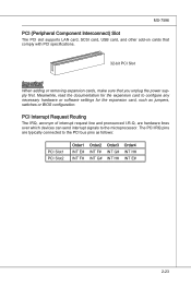
PCI Interrupt Request Routing The IRQ, acronym of interrupt request line and pronounced I-R-Q, are typically connected to the PCI bus pins as jumpers, switches or BIOS configuration. The PCI IRQ pins are hardware lines over which devices can send interrupt signals to configure any necessary hardware or software settings for the ...
PCI Interrupt Request Routing The IRQ, acronym of interrupt request line and pronounced I-R-Q, are typically connected to the PCI bus pins as jumpers, switches or BIOS configuration. The PCI IRQ pins are hardware lines over which devices can send interrupt signals to configure any necessary hardware or software settings for the ...

User Guide
Page 39
Chapter 3 BIOS Setup This chapter provides information on the screen during the system booting up, and requests you to change the default settings for optimum use. You may need to run the Setup program when: ■ An error message appears on the BIOS Setup program and allows you to run SETUP. ■ You want to configure the system for customized features. 2-3-1
Chapter 3 BIOS Setup This chapter provides information on the screen during the system booting up, and requests you to change the default settings for optimum use. You may need to run the Setup program when: ■ An error message appears on the BIOS Setup program and allows you to run SETUP. ■ You want to configure the system for customized features. 2-3-1

User Guide
Page 40
... Intel, N = NVIDIA, A = AMD and V = VIA. 7th - 8th digit refers to the date this chapter are under continuous update for better system performance. It is the BIOS version. Therefore, the description may also restart the system by turning it OFF and On or pressing the RESET button. V2.0 refers to the... BIOS version. 050509 refers to the customer as MS = all standard customers. When the message below appears on the computer and the system will start...
... Intel, N = NVIDIA, A = AMD and V = VIA. 7th - 8th digit refers to the date this chapter are under continuous update for better system performance. It is the BIOS version. Therefore, the description may also restart the system by turning it OFF and On or pressing the RESET button. V2.0 refers to the... BIOS version. 050509 refers to the customer as MS = all standard customers. When the message below appears on the computer and the system will start...

User Guide
Page 41
... field within a sub-menu. The Help screen lists the appropriate keys to use the arrow keys ( ↑↓ ) to select the item. General Help The BIOS setup program provides a General Help screen. Press to exit the Help screen. 3-3 MS-7596 Control Keys Move to the previous item Move to the next...
... field within a sub-menu. The Help screen lists the appropriate keys to use the arrow keys ( ↑↓ ) to select the item. General Help The BIOS setup program provides a General Help screen. Press to exit the Help screen. 3-3 MS-7596 Control Keys Move to the previous item Move to the next...

User Guide
Page 42
...; Standard CMOS Features Use this menu for basic system configurations, such as time, date etc. ▶ Advanced BIOS Features Use this menu to setup the items of the BIOS special enhanced features. ▶ Integrated Peripherals Use this menu to specify your settings for integrated peripherals. ▶ ...to specify your settings for power management. ▶ H/W Monitor This entry shows your PC health status. ▶ BIOS Setting Password Use this menu to set the password for BIOS. ▶ Cell Menu Use this menu to specify your settings for frequency/voltage control and overclocking. ▶ ...
...; Standard CMOS Features Use this menu for basic system configurations, such as time, date etc. ▶ Advanced BIOS Features Use this menu to setup the items of the BIOS special enhanced features. ▶ Integrated Peripherals Use this menu to specify your settings for integrated peripherals. ▶ ...to specify your settings for power management. ▶ H/W Monitor This entry shows your PC health status. ▶ BIOS Setting Password Use this menu to set the password for BIOS. ▶ Cell Menu Use this menu to specify your settings for frequency/voltage control and overclocking. ▶ ...

User Guide
Page 43
MS-7596 Load Fail-Safe Defaults Use this menu to load the default values set by the BIOS vendor for stable system performance. ▶ Load Optimized Defaults Use this menu to load the default values set by the mainboard manufacturer specifically for optimal performance of the mainboard. ▶ Save & Exit Setup Save changes to CMOS and exit setup. ▶ Exit Without Saving Abandon all changes and exit setup. 3-5
MS-7596 Load Fail-Safe Defaults Use this menu to load the default values set by the BIOS vendor for stable system performance. ▶ Load Optimized Defaults Use this menu to load the default values set by the mainboard manufacturer specifically for optimal performance of the mainboard. ▶ Save & Exit Setup Save changes to CMOS and exit setup. ▶ Exit Without Saving Abandon all changes and exit setup. 3-5

User Guide
Page 44
... date from 1 to 31 can be keyed by numeric function keys. [year] The year can be adjusted by BIOS. The time format is . [day] Day of the week, from Jan. Read- ▍ BIOS Setup Standard CMOS Features The items in Standard CMOS Features Menu include some basic setup items. Use the arrow...
... date from 1 to 31 can be keyed by numeric function keys. [year] The year can be adjusted by BIOS. The time format is . [day] Day of the week, from Jan. Read- ▍ BIOS Setup Standard CMOS Features The items in Standard CMOS Features Menu include some basic setup items. Use the arrow...

User Guide
Page 46
▍ BIOS Setup ▶ Hold On The setting determines whether the system will halt on for 15 seconds and then automatically resume its operation. [All Error] The system stops when any detected error. ▶ System Information Press to enter the sub-menu, and the following screen appears. This sub-menu shows the CPU information, BIOS version and memory status of your system (read only). 3-8 When the system stops for the errors preset, it will stop if an error is detected. [No Error] The system does not stop for any error is detected at boot.
▍ BIOS Setup ▶ Hold On The setting determines whether the system will halt on for 15 seconds and then automatically resume its operation. [All Error] The system stops when any detected error. ▶ System Information Press to enter the sub-menu, and the following screen appears. This sub-menu shows the CPU information, BIOS version and memory status of your system (read only). 3-8 When the system stops for the errors preset, it will stop if an error is detected. [No Error] The system does not stop for any error is detected at boot.

User Guide
Page 47
... You should immediately re-enable it to protect it will turn on the Num Lock key when the system is to disable this Flash BIOS Protection function. The only time when you need to set the Num Lock status when the system is powered on the full screen at...Display This item enables this function at all times. Setting to update the BIOS. Advanced BIOS Features MS-7596 ▶ BIOS Flash Protection This function protects the BIOS from accidental corruption by unauthorized users or computer viruses. After updating the BIOS, you want to [On] will skip some check items. ▶ ...
... You should immediately re-enable it to protect it will turn on the Num Lock key when the system is to disable this Flash BIOS Protection function. The only time when you need to set the Num Lock status when the system is powered on the full screen at...Display This item enables this function at all times. Setting to update the BIOS. Advanced BIOS Features MS-7596 ▶ BIOS Flash Protection This function protects the BIOS from accidental corruption by unauthorized users or computer viruses. After updating the BIOS, you want to [On] will skip some check items. ▶ ...

User Guide
Page 48
... graphics adapter. ▶ PCI Latency Timer This item controls how long each PCI device can to enable it via the various ACPI methods. 3-10 ▍ BIOS Setup ▶ IOAPIC Function This field is used to enable/ disable SVM. ▶ Chipset Feature Press to enter the sub-menu and the following screen...
... graphics adapter. ▶ PCI Latency Timer This item controls how long each PCI device can to enable it via the various ACPI methods. 3-10 ▍ BIOS Setup ▶ IOAPIC Function This field is used to enable/ disable SVM. ▶ Chipset Feature Press to enter the sub-menu and the following screen...

User Guide
Page 49
... controls the exact memory size shared to the VGA card. ▶ SIDEPORT Memory Frequency This item allows you to set the first boot device where BIOS attempts to load the disk operating system. ▶ Boot From Other Device Setting the option to [Yes] allows the system to try to the onboard...
... controls the exact memory size shared to the VGA card. ▶ SIDEPORT Memory Frequency This item allows you to set the first boot device where BIOS attempts to load the disk operating system. ▶ Boot From Other Device Setting the option to [Yes] allows the system to try to the onboard...
User Guide
Page 50
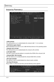
▍ BIOS Setup Integrated Peripherals ▶ USB Controller This setting allows you to enable/disable the onboard USB 1.1/ 2.0 controller. ▶ USB Device Legacy Support Select [Enabled] if ...
▍ BIOS Setup Integrated Peripherals ▶ USB Controller This setting allows you to enable/disable the onboard USB 1.1/ 2.0 controller. ▶ USB Device Legacy Support Select [Enabled] if ...
User Guide
Page 51
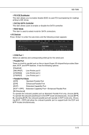
..., choose [EPP]. To operate the onboard parallel port in ECP mode only. MS-7596 ▶ PCI IDE BusMaster This item allows you to enable/ disable BIOS to used PCI busmastering for reading/ writing to IDE drives. ▶ OnChip SATA Controller This item allows users to enable or disable the SATA controller...
..., choose [EPP]. To operate the onboard parallel port in ECP mode only. MS-7596 ▶ PCI IDE BusMaster This item allows you to enable/ disable BIOS to used PCI busmastering for reading/ writing to IDE drives. ▶ OnChip SATA Controller This item allows users to enable or disable the SATA controller...

User Guide
Page 52
...save energy. In this state, no system context is lost (CPU or chipset) and hardware maintains all sys- Settings are available only when the BIOS supports S3 sleep mode. ▶ ACPI Function This item is to activate the ACPI (Advanced Configuration and Power Management Interface) Function. tem's context.../ 2000/ ME/ XP, select [Enabled]. ▶ ACPI Standby State This item specifies the power saving modes for ACPI function. ▍ BIOS Setup Power Management Setup Important S3-related functions described in this section are : [S1] The S1 sleep mode is a low power state.
...save energy. In this state, no system context is lost (CPU or chipset) and hardware maintains all sys- Settings are available only when the BIOS supports S3 sleep mode. ▶ ACPI Function This item is to activate the ACPI (Advanced Configuration and Power Management Interface) Function. tem's context.../ 2000/ ME/ XP, select [Enabled]. ▶ ACPI Standby State This item specifies the power saving modes for ACPI function. ▍ BIOS Setup Power Management Setup Important S3-related functions described in this section are : [S1] The S1 sleep mode is a low power state.
User Guide
Page 53
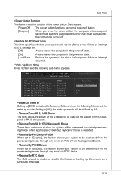
... before power failure or interrupt occurred. ▶ Wake Up Event Setup Press and the following sub-menu appears. ▶ Wake Up Event By Setting to [BIOS] activates the following fields, and use the following fields to set the wake up events. Setting to [OS], the wake up events will be defined...
... before power failure or interrupt occurred. ▶ Wake Up Event Setup Press and the following sub-menu appears. ▶ Wake Up Event By Setting to [BIOS] activates the following fields, and use the following fields to set the wake up events. Setting to [OS], the wake up events will be defined...
User Guide
Page 54
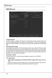
The setting of recording the chassis intrusion status and issuing a warning message if the chassis is once opened. ▍ BIOS Setup H/W Monitor ▶ Chassis Intrusion The field enables or disables the feature of the field will be activated. You can control the CPU fan speed ...
The setting of recording the chassis intrusion status and issuing a warning message if the chassis is once opened. ▍ BIOS Setup H/W Monitor ▶ Chassis Intrusion The field enables or disables the feature of the field will be activated. You can control the CPU fan speed ...


