User Guide
Page 4
... the emission limits. iv Notice 2 Shielded interface cables and A.C. FCC-B Radio Frequency Interference Statement T h is no guarantee that may cause undesired operation. Micro-Star International MS-7576 This device complies with the limits for compliance could void the user's authority to comply with Part 15 of the FCC Rules.
... the emission limits. iv Notice 2 Shielded interface cables and A.C. FCC-B Radio Frequency Interference Statement T h is no guarantee that may cause undesired operation. Micro-Star International MS-7576 This device complies with the limits for compliance could void the user's authority to comply with Part 15 of the FCC Rules.
User Guide
Page 11
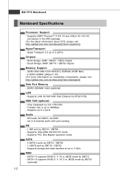
... X2 processors in the AM3 package. (For the latest information about CPU, please visit ht t p : / / global. Transfer rate is up to 5.2GT/s Chipset - Supports storage and data transfers at up to 2 ports Audio - c om . North Bridge: AMD® 790GX / 780G chipset - South Bridge: AMD® SB710 / SB750 chipset Memory Support - c om . DDR3... / ind ex. Supports Ultra DMA 66/100/133 mode - Up to 3 Gb/s RAID - p hp?func =t est report ) Side Port M emory - Chip integrated by SB710 / SB750 - MS-7576 Mainboard Mainboard Specifications Processor Support - t w / index. m s i.
... X2 processors in the AM3 package. (For the latest information about CPU, please visit ht t p : / / global. Transfer rate is up to 5.2GT/s Chipset - Supports storage and data transfers at up to 2 ports Audio - c om . North Bridge: AMD® 790GX / 780G chipset - South Bridge: AMD® SB710 / SB750 chipset Memory Support - c om . DDR3... / ind ex. Supports Ultra DMA 66/100/133 mode - Up to 3 Gb/s RAID - p hp?func =t est report ) Side Port M emory - Chip integrated by SB710 / SB750 - MS-7576 Mainboard Mainboard Specifications Processor Support - t w / index. m s i.
User Guide
Page 13
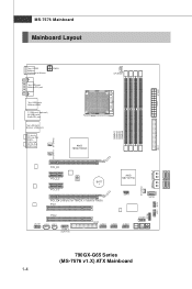
In M: Li ne-O ut B:Mic T:R S - MS-7576 Mainboard Mainboard Layout Top : SPDIF Botto m: Keyboard or Mouse PWR1 Top: VGA port Bottom:DVI port Top: USB ports Bottom:HDMI T:1394 port (optional) M:USB ports B:eSATA port Top:LAN Jack Bottom: USB ports T:L ine- O ut M: C S -O ut B:SS-Out CPUFAN1 JPW R1 IDE1 SYSFAN1 SYSFAN2 S Y S FA N 3 S ATA 2_3 S ATA4_ 5 JTPM1 JFP1 JFP2 JAUD1 JCD1 JSP1 J1394_1 (opt i on al) BATT + JSPI1 SATA1 FDD1 JUSB1 JUSB2 JUSB3 JCOM1 790GX-G65 Series (MS-7576 v1.X) ATX Mainboard 1-4
In M: Li ne-O ut B:Mic T:R S - MS-7576 Mainboard Mainboard Layout Top : SPDIF Botto m: Keyboard or Mouse PWR1 Top: VGA port Bottom:DVI port Top: USB ports Bottom:HDMI T:1394 port (optional) M:USB ports B:eSATA port Top:LAN Jack Bottom: USB ports T:L ine- O ut M: C S -O ut B:SS-Out CPUFAN1 JPW R1 IDE1 SYSFAN1 SYSFAN2 S Y S FA N 3 S ATA 2_3 S ATA4_ 5 JTPM1 JFP1 JFP2 JAUD1 JCD1 JSP1 J1394_1 (opt i on al) BATT + JSPI1 SATA1 FDD1 JUSB1 JUSB2 JUSB3 JCOM1 790GX-G65 Series (MS-7576 v1.X) ATX Mainboard 1-4

User Guide
Page 18
... lever. Press the CPU down firmly into the socket and close the lever with your f ingers pressing tightly on top of the CPU. Pull the lever sideways away from the socket. MS-7576 Mainboard CPU & Cooler Installation W hen you are installing the CPU, make sure the CPU is properly and completely... embedded into the socket. 2-4 As the CPU is likely to your...
... lever. Press the CPU down firmly into the socket and close the lever with your f ingers pressing tightly on top of the CPU. Pull the lever sideways away from the socket. MS-7576 Mainboard CPU & Cooler Installation W hen you are installing the CPU, make sure the CPU is properly and completely... embedded into the socket. 2-4 As the CPU is likely to your...
User Guide
Page 20
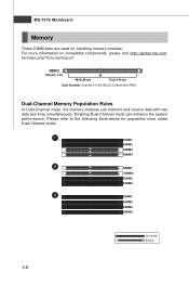
MS-7576 Mainboard Memory These DIMM slots are used for population rules under Dual-Channel mode. 1 DIMM1 DIMM2 DIMM3 DIMM4 2 DIMM1 DIMM2 DIMM3 DIMM4 3 DIMM1 DIMM2 DIMM3 ... Memory Population Rules In Dual-Channel mode, the memory modules can enhance the system performance. For more information on compatible components, please visit http://global.msi.com.
MS-7576 Mainboard Memory These DIMM slots are used for population rules under Dual-Channel mode. 1 DIMM1 DIMM2 DIMM3 DIMM4 2 DIMM1 DIMM2 DIMM3 DIMM4 3 DIMM1 DIMM2 DIMM3 ... Memory Population Rules In Dual-Channel mode, the memory modules can enhance the system performance. For more information on compatible components, please visit http://global.msi.com.

User Guide
Page 22
...PWR1 This 4-pin power connector is inserted in the proper orientation and the pins are connected to proper ATX power supplies to the CPU. Then push down the power supply firmly into the connector. Power supply of the power supply is used to provide power to ensure... 3 12V 4 12V pin 13 pin 12 Important 1. Make sure that all the connectors are aligned. There is highly recommended for system stability. 2-8 MS-7576 Mainboard Power Supply ATX 24-Pin Power Connector: JPWR1 This connector allows you to avoid wrong installation. To connect the ATX 24-pin power supply...
...PWR1 This 4-pin power connector is inserted in the proper orientation and the pins are connected to proper ATX power supplies to the CPU. Then push down the power supply firmly into the connector. Power supply of the power supply is used to provide power to ensure... 3 12V 4 12V pin 13 pin 12 Important 1. Make sure that all the connectors are aligned. There is highly recommended for system stability. 2-8 MS-7576 Mainboard Power Supply ATX 24-Pin Power Connector: JPWR1 This connector allows you to avoid wrong installation. To connect the ATX 24-pin power supply...
User Guide
Page 24
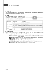
... cable to the Local Area Network (LAN). Center/ Subwoofer Out in 4/ 5.1/ 7.1 channel mode. SS-Out (Gray) - Line-Out (Green) - CS-Out (Orange) - RS-Out (Black) - MS-7576 Mainboard USB Port The USB (Universal Serial Bus) port is for attaching USB devices such as keyboard, mouse, or other audio devices.
... cable to the Local Area Network (LAN). Center/ Subwoofer Out in 4/ 5.1/ 7.1 channel mode. SS-Out (Gray) - Line-Out (Green) - CS-Out (Orange) - RS-Out (Black) - MS-7576 Mainboard USB Port The USB (Universal Serial Bus) port is for attaching USB devices such as keyboard, mouse, or other audio devices.
User Guide
Page 26
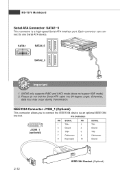
... allows you to one Serial ATA device. SATA1 SATA4_5 SATA2_3 Important 1. Each connector can connect to connect the IEEE1394 device via an optional IEEE1394 bracket. MS-7576 Mainboard Serial ATA Connector: SATA1~5 This connector is a high-speed Serial ATA interface port. Otherwise, data loss may occur during transmission.
... allows you to one Serial ATA device. SATA1 SATA4_5 SATA2_3 Important 1. Each connector can connect to connect the IEEE1394 device via an optional IEEE1394 bracket. MS-7576 Mainboard Serial ATA Connector: SATA1~5 This connector is a high-speed Serial ATA interface port. Otherwise, data loss may occur during transmission.
User Guide
Page 28
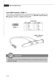
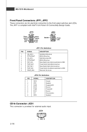
MS-7576 Mainboard Front USB Connector: JUSB1~3 This connector, compliant with Intel® I/O Connectivity Design Guide, is ideal for connecting high-speed USB interface peripherals such as USB HDD, digital cameras, MP3 players, printers, modems and the like. 9 1 10 2 JUSB1~3 Pin Definition PIN SIGNAL 1 VCC 3 USB0- 5 USB0+ 7 GND 9 Key (no pin) PIN SIGNAL 2 VCC 4 USB1- 6 USB1+ 8 GND 10 USBOC USB 2.0 Bracket (Optional) Important Note that the pins of VCC and GND must be connected correctly to avoid possible damage. 2-14
MS-7576 Mainboard Front USB Connector: JUSB1~3 This connector, compliant with Intel® I/O Connectivity Design Guide, is ideal for connecting high-speed USB interface peripherals such as USB HDD, digital cameras, MP3 players, printers, modems and the like. 9 1 10 2 JUSB1~3 Pin Definition PIN SIGNAL 1 VCC 3 USB0- 5 USB0+ 7 GND 9 Key (no pin) PIN SIGNAL 2 VCC 4 USB1- 6 USB1+ 8 GND 10 USBOC USB 2.0 Bracket (Optional) Important Note that the pins of VCC and GND must be connected correctly to avoid possible damage. 2-14
User Guide
Page 30
... Speaker+ CD-In Connector: JCD1 This connector is compliant with Intel® Front Panel I/O Connectivity Design Guide. Switch - JFP1 10 Power Switch + Power LED 2 9 + Reset - MS-7576 Mainboard Front Panel Connectors: JFP1, JFP2 These connectors are for external audio input.
... Speaker+ CD-In Connector: JCD1 This connector is compliant with Intel® Front Panel I/O Connectivity Design Guide. Switch - JFP1 10 Power Switch + Power LED 2 9 + Reset - MS-7576 Mainboard Front Panel Connectors: JFP1, JFP2 These connectors are for external audio input.
User Guide
Page 32
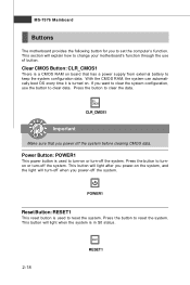
... button will explain how to change your motherboard's function through the use the button to clear the data. This button will turn -off the system. MS-7576 Mainboard Buttons The motherboard provides the following button for you power-off the system.
... button will explain how to change your motherboard's function through the use the button to clear the data. This button will turn -off the system. MS-7576 Mainboard Buttons The motherboard provides the following button for you power-off the system.

User Guide
Page 34
MS-7576 Mainboard Slots PCI (Peripheral Component Interconnect) Express Slot The PCI Express slot supports the PCI Express interface expansion card. PCI_E2 supports up to PCI Express ... up to PCI Express x1 speed. PCIE slot allocation for 780G chipset 2-20 PCI_E1 supports up to PCI Express x16 speed. PCIE slot allocation for 790GX chipset PCI_E1 supports up to PCI Express x16 speed. When dual graphic cards enabled, it will turn to 4.0 GB/s transfer rate. PCI_E3 supports up to...
MS-7576 Mainboard Slots PCI (Peripheral Component Interconnect) Express Slot The PCI Express slot supports the PCI Express interface expansion card. PCI_E2 supports up to PCI Express ... up to PCI Express x1 speed. PCIE slot allocation for 780G chipset 2-20 PCI_E1 supports up to PCI Express x16 speed. PCIE slot allocation for 790GX chipset PCI_E1 supports up to PCI Express x16 speed. When dual graphic cards enabled, it will turn to 4.0 GB/s transfer rate. PCI_E3 supports up to...
User Guide
Page 36
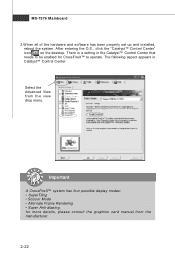
for CrossFireX™ to operate. There is a setting in Catalyst™ Control Center: Select the Advanced View from the manufacturer. 2-22 MS-7576 Mainboard 3.W hen all of the hardware and software has been properly set up and installed, reboot the system. After entering the O.S., click the "Catalyst™ ...
for CrossFireX™ to operate. There is a setting in Catalyst™ Control Center: Select the Advanced View from the manufacturer. 2-22 MS-7576 Mainboard 3.W hen all of the hardware and software has been properly set up and installed, reboot the system. After entering the O.S., click the "Catalyst™ ...
User Guide
Page 38
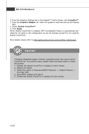
... in Advanced BIOS Features -> Chipset Feature -> On-Chip VGA 4. To avoid the issue, please follow the steps below to http://game.amd.com/us-en/crossfirex_hybrid.aspx Important Changing integrated graphic memory operating mode may cause Hybrid CrossFire fail. Select the option in Catalyst Control Center....5. From the Graphics Adapter list, select the graphics card that acts as are all cards in Catalyst Control Center. 2. MS-7576 Mainboard 2. From the Graphics Settings tree in the CatalystTM Control Center, click CrossFireTM. 3. Select Enable CrossFireTM 5. Reboot into BIOS 3.
... in Advanced BIOS Features -> Chipset Feature -> On-Chip VGA 4. To avoid the issue, please follow the steps below to http://game.amd.com/us-en/crossfirex_hybrid.aspx Important Changing integrated graphic memory operating mode may cause Hybrid CrossFire fail. Select the option in Catalyst Control Center....5. From the Graphics Adapter list, select the graphics card that acts as are all cards in Catalyst Control Center. 2. MS-7576 Mainboard 2. From the Graphics Settings tree in the CatalystTM Control Center, click CrossFireTM. 3. Select Enable CrossFireTM 5. Reboot into BIOS 3.
User Guide
Page 41
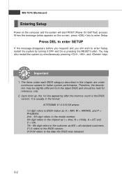
... under continuous update for reference only. 2. W hen the message below appears on the computer and the system will start POST (Power On Self Test) process. MS-7576 Mainboard Entering Setup Power on the screen, press key to the date this chapter are under each BIOS category described in the format: A7576AMS V1... digit refers to BIOS maker as A = AMI, W = AWARD, and P = PHOENIX. 2nd - 5th digit refers to the model number. 6th digit refers to the chipset as MS = all standard customers.
... under continuous update for reference only. 2. W hen the message below appears on the computer and the system will start POST (Power On Self Test) process. MS-7576 Mainboard Entering Setup Power on the screen, press key to the date this chapter are under each BIOS category described in the format: A7576AMS V1... digit refers to BIOS maker as A = AMI, W = AWARD, and P = PHOENIX. 2nd - 5th digit refers to the model number. 6th digit refers to the chipset as MS = all standard customers.
User Guide
Page 43
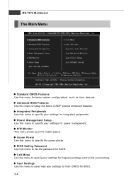
.... H/W Monitor This entry shows your settings to/ from CMOS for BIOS. 3-4 Integrated Peripherals Use this menu for basic system configurations, such as time, date etc. MS-7576 Mainboard The Main Menu Standard CMOS Features Use this menu to specify your settings for integrated peripherals. Advanced BIOS Features Use this menu to save...
.... H/W Monitor This entry shows your settings to/ from CMOS for BIOS. 3-4 Integrated Peripherals Use this menu for basic system configurations, such as time, date etc. MS-7576 Mainboard The Main Menu Standard CMOS Features Use this menu to specify your settings for integrated peripherals. Advanced BIOS Features Use this menu to save...
User Guide
Page 45
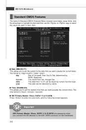
... you want (usually the current date). Read-only. IDE Primary Master/ Slave, SATA1~5 & E-SATA Press to enter the sub-menu, and the following screen appears. MS-7576 Mainboard Standard CMOS Features The items in each item. year The year can be adjusted by users. through Dec.
... you want (usually the current date). Read-only. IDE Primary Master/ Slave, SATA1~5 & E-SATA Press to enter the sub-menu, and the following screen appears. MS-7576 Mainboard Standard CMOS Features The items in each item. year The year can be adjusted by users. through Dec.
User Guide
Page 47
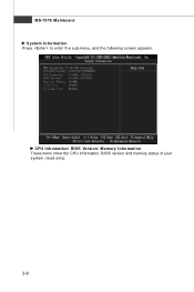
CPU Infromation/ BIOS Version/ M emory Information These items show the CPU information, BIOS version and memory status of your system (read only). 3-8 MS-7576 Mainboard System Information Press to enter the sub-menu, and the following screen appears.
CPU Infromation/ BIOS Version/ M emory Information These items show the CPU information, BIOS version and memory status of your system (read only). 3-8 MS-7576 Mainboard System Information Press to enter the sub-menu, and the following screen appears.
User Guide
Page 49
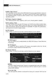
...Latency Timer This item controls how long each PCI device can conduct transactions for a longer time and thus improve the effective PCI bandwidth. CPU Feature Press to enter the sub-menu and the following screen appears: SVM Support This item allows you to enter the sub-menu and...The HPET (High Precision Event Timers) is a component that is your operating system. Chipset Feature Press to enable/disable the AMD SVM (Secure Virtual Machine) Tec hn ology. MS-7576 Mainboard MPS Table Version This field allows you to select which MPS (Multi-Processor Specification) version to it , and will ...
...Latency Timer This item controls how long each PCI device can conduct transactions for a longer time and thus improve the effective PCI bandwidth. CPU Feature Press to enter the sub-menu and the following screen appears: SVM Support This item allows you to enter the sub-menu and...The HPET (High Precision Event Timers) is a component that is your operating system. Chipset Feature Press to enable/disable the AMD SVM (Secure Virtual Machine) Tec hn ology. MS-7576 Mainboard MPS Table Version This field allows you to select which MPS (Multi-Processor Specification) version to it , and will ...
User Guide
Page 51
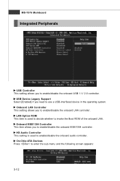
... you need to use a USB-interfaced device in the operating system. Onboard IEEE1394 Controller This item allows you to enable/disable the onboard USB 1.1/ 2.0 controller. MS-7576 Mainboard Integrated Peripherals USB Controller This setting allows you to enable/disable the onboard IEEE1394 controller.
... you need to use a USB-interfaced device in the operating system. Onboard IEEE1394 Controller This item allows you to enable/disable the onboard USB 1.1/ 2.0 controller. MS-7576 Mainboard Integrated Peripherals USB Controller This setting allows you to enable/disable the onboard IEEE1394 controller.


