
User Guide
Page 12
... connector - 1 CD-In connector - 1 Front Panel Audio pinheader - 1 Chassis Intrusion Switch pinheader - 1 Serial port connector - 1 TPM pinheader (optional) - 1 OC switch - 1 Power LED Button - 1 Reset LED Button - 1 Clear CMOS Button Slots For 790GX - 1 PCI Express x16 slot supports up to PCI Express x16 speed. When dual graphic cards enabled, it will turn to x8...
... connector - 1 CD-In connector - 1 Front Panel Audio pinheader - 1 Chassis Intrusion Switch pinheader - 1 Serial port connector - 1 TPM pinheader (optional) - 1 OC switch - 1 Power LED Button - 1 Reset LED Button - 1 Clear CMOS Button Slots For 790GX - 1 PCI Express x16 slot supports up to PCI Express x16 speed. When dual graphic cards enabled, it will turn to x8...
User Guide
Page 24
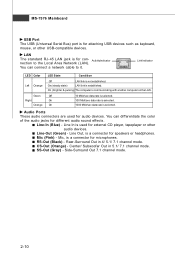
LAN The standard RJ-45 LAN jack is not established. Link Indicator LED Color Left Orange Green Right Orange LED State Condition Off LAN link is for con- On 100 Mbit/sec data rate is for speakers or headphones. You can connect a network cable to ...
LAN The standard RJ-45 LAN jack is not established. Link Indicator LED Color Left Orange Green Right Orange LED State Condition Off LAN link is for con- On 100 Mbit/sec data rate is for speakers or headphones. You can connect a network cable to ...
User Guide
Page 30
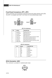
...SLP 3 HD_LED - 4 FP PW R/SLP 5 RST_SW - 6 PW R_SW + 7 RST_SW + 8 PW R_SW - 9 RSVD_DNU DESCRIPTION Hard disk LED pull-up MSG LED pull-up Hard disk active LED MSG LED pull-up Reset Switch low reference pull-down to GND Power Switch high reference pull-up Reset Switch high reference pull... JCD1 This connector is compliant with Intel® Front Panel I/O Connectivity Design Guide. JCD1 2-16 L GND R JFP1 10 Power Switch + Power LED 2 9 + Reset - MS-7576 Mainboard Front Panel Connectors: JFP1, JFP2 These connectors are for external audio input. Switch - The JFP1 is ...
...SLP 3 HD_LED - 4 FP PW R/SLP 5 RST_SW - 6 PW R_SW + 7 RST_SW + 8 PW R_SW - 9 RSVD_DNU DESCRIPTION Hard disk LED pull-up MSG LED pull-up Hard disk active LED MSG LED pull-up Reset Switch low reference pull-down to GND Power Switch high reference pull-up Reset Switch high reference pull... JCD1 This connector is compliant with Intel® Front Panel I/O Connectivity Design Guide. JCD1 2-16 L GND R JFP1 10 Power Switch + Power LED 2 9 + Reset - MS-7576 Mainboard Front Panel Connectors: JFP1, JFP2 These connectors are for external audio input. Switch - The JFP1 is ...

User Guide
Page 48
... function protects the BIOS from accidental corruption by unauthorized users or computer viruses. Setting to [On] will skip some check items. Boot Up Num-Lock LED This setting is to set the Num Lock status when the system is used to run in APIC mode. Setting to update the BIOS. To...
... function protects the BIOS from accidental corruption by unauthorized users or computer viruses. Setting to [On] will skip some check items. Boot Up Num-Lock LED This setting is to set the Num Lock status when the system is used to run in APIC mode. Setting to update the BIOS. To...

User Guide
Page 57
MS-7576 Mainboard Green Power CPU Phase Control W hen set to [Auto], the hardware will auto adjust the CPU power phase according to the loading of CPU to enable/disable the CPU Power Phase LED. 3-18 LED Power Control This item allows you to reach the best power saving function.
MS-7576 Mainboard Green Power CPU Phase Control W hen set to [Auto], the hardware will auto adjust the CPU power phase according to the loading of CPU to enable/disable the CPU Power Phase LED. 3-18 LED Power Control This item allows you to reach the best power saving function.


