User Guide
Page 2
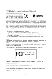
Notice 2 Shielded interface cables and A.C. Micro-Star International Axis 690 Series This device complies with Part 15 of the FCC rules. ii However, there is connected. =Consult the dealer or an experienced radio/television technician for help. power cord, if any interference received, including interfer ence that interference will not occur in a particular installation. If this equipment does cause harmful interference...
Notice 2 Shielded interface cables and A.C. Micro-Star International Axis 690 Series This device complies with Part 15 of the FCC rules. ii However, there is connected. =Consult the dealer or an experienced radio/television technician for help. power cord, if any interference received, including interfer ence that interference will not occur in a particular installation. If this equipment does cause harmful interference...
User Guide
Page 9
... Assembly 3-1 O ver view...3-2 Installation Procedures 3-4 Chapter 4. Realtek ALC888 Audio A-1 Installing the Realtek HD Audio Driver A-2 Software Configuration A-4 Hardware Setup A-19 ix BIOS Setup 4-1 Entering Setup 4-2 The Menu Bar 4-4 Main...4-6 Advanced...4-8 Boot...4-16 Security...4-18 Chipset...4-20 Power...4-24 Exit...4-25 Appendix A. Hardware Setup 2-1 Mainboard Layout 2-2 CPU (Central Processing Unit 2-3 Memory...2-6 Power Supply 2-7 Front Panel...2-8 Back Panel...2-9 Connectors...2-11 Jumper...2-16 Slot...2-17 Chapter 3. Patent Numbers iii Revision History...
... Assembly 3-1 O ver view...3-2 Installation Procedures 3-4 Chapter 4. Realtek ALC888 Audio A-1 Installing the Realtek HD Audio Driver A-2 Software Configuration A-4 Hardware Setup A-19 ix BIOS Setup 4-1 Entering Setup 4-2 The Menu Bar 4-4 Main...4-6 Advanced...4-8 Boot...4-16 Security...4-18 Chipset...4-20 Power...4-24 Exit...4-25 Appendix A. Hardware Setup 2-1 Mainboard Layout 2-2 CPU (Central Processing Unit 2-3 Memory...2-6 Power Supply 2-7 Front Panel...2-8 Back Panel...2-9 Connectors...2-11 Jumper...2-16 Slot...2-17 Chapter 3. Patent Numbers iii Revision History...
User Guide
Page 12
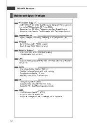
... - Supports PCI Express LAN 10/ 100/ 1000 Fast Ethernet by AMD® SB600 - Compliant with Fan Speed Control - Meet Microsoft Vista Premium spec IDE - 1 IDE port by Realtek® RTL8111C Audio - Supports storage and data transfers up to 300MB/s 1-2 Supports 4 pin CPU Fan Pinheader with Azalia 1.0 spec - South Bridge: AMD® SB600 chipset Memory Support - Supports Ultra DMA 66/ 100/ 133 mode - Supports 3 pin System Fan Pinheader with jack sensing - Supports PIO, Bus Master operation mode SATA - 2 SATA II ports...
... - Supports PCI Express LAN 10/ 100/ 1000 Fast Ethernet by AMD® SB600 - Compliant with Fan Speed Control - Meet Microsoft Vista Premium spec IDE - 1 IDE port by Realtek® RTL8111C Audio - Supports storage and data transfers up to 300MB/s 1-2 Supports 4 pin CPU Fan Pinheader with Azalia 1.0 spec - South Bridge: AMD® SB600 chipset Memory Support - Supports Ultra DMA 66/ 100/ 133 mode - Supports 3 pin System Fan Pinheader with jack sensing - Supports PIO, Bus Master operation mode SATA - 2 SATA II ports...
User Guide
Page 14
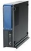
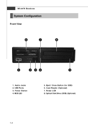
Eject/ Close Button (for ODD) 6. Power LED 8. Optical Disk Drive (ODD) (Optional) 1-4 Card Reader (Optional) 7. USB Ports 3. Power Button 4. MS-6478 Barebone System Configuration Front View 1. Audio Jacks 2. HDD LED 5.
Eject/ Close Button (for ODD) 6. Power LED 8. Optical Disk Drive (ODD) (Optional) 1-4 Card Reader (Optional) 7. USB Ports 3. Power Button 4. MS-6478 Barebone System Configuration Front View 1. Audio Jacks 2. HDD LED 5.
User Guide
Page 23
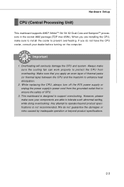
.... Hardware Setup CPU (Central Processing Unit) This mainboard supports AMD® AthlonTM 64/ 64 X2 Dual-Core and SempronTM processors in the socket AM2 package (TDP max 65W ). W hen you do not guarantee the damages or risks caused by inadequate operation or beyond product specifications is designed to prevent overheating. If you are installing the CPU, make sure your dealer before turning...
.... Hardware Setup CPU (Central Processing Unit) This mainboard supports AMD® AthlonTM 64/ 64 X2 Dual-Core and SempronTM processors in the socket AM2 package (TDP max 65W ). W hen you do not guarantee the damages or risks caused by inadequate operation or beyond product specifications is designed to prevent overheating. If you are installing the CPU, make sure your dealer before turning...
User Guide
Page 28
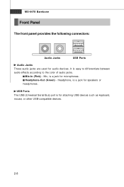
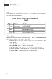
It is a jack for speakers or h eadp h on es . MS-6478 Barebone Front Panel The front panel provides the following connectors: Audio Jacks USB Ports Audio Jacks These audio jacks are used for attaching USB devices such as keyboard, mouse, or other USB-compatible devices. 2-8 Mic-In (Pink) - Mic, is easy to differentiate between audio effects according to the color of audio jacks. USB Ports The USB (Universal Serial Bus) port is a jack for microphones. Headphone, is for audio devices. Headphone-Out (Green) -
It is a jack for speakers or h eadp h on es . MS-6478 Barebone Front Panel The front panel provides the following connectors: Audio Jacks USB Ports Audio Jacks These audio jacks are used for attaching USB devices such as keyboard, mouse, or other USB-compatible devices. 2-8 Mic-In (Pink) - Mic, is easy to differentiate between audio effects according to the color of audio jacks. USB Ports The USB (Universal Serial Bus) port is a jack for microphones. Headphone, is for audio devices. Headphone-Out (Green) -
User Guide
Page 29
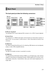
...; mouse/ keyboard. Serial Ports The serial port is an all-digital audio/ video interface capable of transmitting uncompressed streams. HDMI supports all TV format, including standard, enhanced, or high-definition video, plus multi-channel digital audio on a single cable. 2-9 HDMI Port The High-Definition Multimedia Interface (HDMI) is a 16550A high speed communications port that sends/ receives 16 bytes FIFOs. Hardware Setup Back Panel The back panel provides the following connectors: Mouse (Green) Serial Ports Keyboard (Purple) LAN VGA Port USB Ports HDMI Port RS...
...; mouse/ keyboard. Serial Ports The serial port is an all-digital audio/ video interface capable of transmitting uncompressed streams. HDMI supports all TV format, including standard, enhanced, or high-definition video, plus multi-channel digital audio on a single cable. 2-9 HDMI Port The High-Definition Multimedia Interface (HDMI) is a 16550A high speed communications port that sends/ receives 16 bytes FIFOs. Hardware Setup Back Panel The back panel provides the following connectors: Mouse (Green) Serial Ports Keyboard (Purple) LAN VGA Port USB Ports HDMI Port RS...
User Guide
Page 30
... easy to differentiate between audio effects according to it. Mic, is a jack for speakers or headphones. You can connect a network cable to the color of audio jacks. Audio Jacks These audio jacks are used for connection to the Local Area Network (LAN). RS-Out (Black) - SS-Out (Gray) - MS-6478 Barebone LAN The standard RJ-45 LAN jack is for external CD player, tapeplayer or other audio devices.
... easy to differentiate between audio effects according to it. Mic, is a jack for speakers or headphones. You can connect a network cable to the color of audio jacks. Audio Jacks These audio jacks are used for connection to the Local Area Network (LAN). RS-Out (Black) - SS-Out (Gray) - MS-6478 Barebone LAN The standard RJ-45 LAN jack is for external CD player, tapeplayer or other audio devices.
User Guide
Page 31
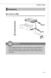
IDEB1 Important If you install two IDE devices on the same cable, you must configure the drives separately to IDE device's documentation supplied by setting jumpers. Refer to master / slave mode by the vendors for jumper setting instructions. 2-11 Hardware Setup Connectors IDE Connector: IDEB1 This connector supports IDE hard disk drives, optical disk drives and other IDE devices.
IDEB1 Important If you install two IDE devices on the same cable, you must configure the drives separately to IDE device's documentation supplied by setting jumpers. Refer to master / slave mode by the vendors for jumper setting instructions. 2-11 Hardware Setup Connectors IDE Connector: IDEB1 This connector supports IDE hard disk drives, optical disk drives and other IDE devices.
User Guide
Page 33
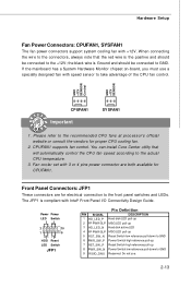
... automatically control the CPU fan speed according to the +12V; You can install Core Center utility that the red wire is the positive and should be connected to the actual CPU temperature. 3. The JFP1 is Ground and should be connected to GND. Please refer to the front panel switches and LEDs. CPUFAN1 supports fan control. Front Panel Connectors: JFP1 These connectors are both available for proper CPU cooling fan. 2. Power Power LED Switch + - 2 10 1 9 +- -+ HDD Reset LED Switch JFP1 PIN SIGNAL...
... automatically control the CPU fan speed according to the +12V; You can install Core Center utility that the red wire is the positive and should be connected to the actual CPU temperature. 3. The JFP1 is Ground and should be connected to GND. Please refer to the front panel switches and LEDs. CPUFAN1 supports fan control. Front Panel Connectors: JFP1 These connectors are both available for proper CPU cooling fan. 2. Power Power LED Switch + - 2 10 1 9 +- -+ HDD Reset LED Switch JFP1 PIN SIGNAL...
User Guide
Page 37
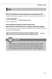
...) Express Slot The Mini-PCI Express slot supports the Mini-PCI Express interface expansion card. Mini-PCI Express Slot PCI (Peripheral Component Interconnect) Slot (No function for this model due to configure any necessary hardware or software settings for the expansion card to chassis mechanism design) The PCI slot supports LAN card, SCSI card, USB card, and other add-on cards that you unplug the power supply first. Meanwhile, read the documentation for the expansion card, such as jumpers, switches or BIOS configuration...
...) Express Slot The Mini-PCI Express slot supports the Mini-PCI Express interface expansion card. Mini-PCI Express Slot PCI (Peripheral Component Interconnect) Slot (No function for this model due to configure any necessary hardware or software settings for the expansion card to chassis mechanism design) The PCI slot supports LAN card, SCSI card, USB card, and other add-on cards that you unplug the power supply first. Meanwhile, read the documentation for the expansion card, such as jumpers, switches or BIOS configuration...
User Guide
Page 40
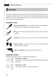
... Cover, Card Reader and Optical Disk Drive. Installation Screws Two types of screws are used in assembling the barebone: Screw type 1: M3XL4 This screw is used to connect some connectors or cables. Installation Tools Cross type screwdriver, can be used to install Card Reader, Hard Disk Drive, Optical Disk Drive and stand. Pliers, can prevent yourself f rom being incised and suffering the static charge. MS-6478 Barebone Overview The built-in components of the barebone include power supply and CPU fan...
... Cover, Card Reader and Optical Disk Drive. Installation Screws Two types of screws are used in assembling the barebone: Screw type 1: M3XL4 This screw is used to connect some connectors or cables. Installation Tools Cross type screwdriver, can be used to install Card Reader, Hard Disk Drive, Optical Disk Drive and stand. Pliers, can prevent yourself f rom being incised and suffering the static charge. MS-6478 Barebone Overview The built-in components of the barebone include power supply and CPU fan...
User Guide
Page 47
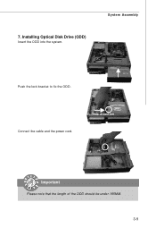
Installing Optical Disk Drive (ODD) Insert the ODD into the system. Connect the cable and the power cord. This direction Important Please note that the length of the ODD should be under 185MM. 3-9 System Assembly Push the lock bracket to fix the ODD. 7.
Installing Optical Disk Drive (ODD) Insert the ODD into the system. Connect the cable and the power cord. This direction Important Please note that the length of the ODD should be under 185MM. 3-9 System Assembly Push the lock bracket to fix the ODD. 7.
User Guide
Page 54
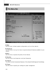
MS-6478 Barebone The Menu Bar Main Use this menu for power management. 4-4 Security Use this menu to specify the priority of the onboard Northbridge and Southbridge. Power Use this menu to set Supervisor and User Passwords. Boot Use this menu to set up the items of special enhanced features available on your settings for basic system configurations, such as time, date etc. Chipset This menu controls the advanced features of boot devices. Ad v a nc e d Use this menu to specify your system.
MS-6478 Barebone The Menu Bar Main Use this menu for power management. 4-4 Security Use this menu to specify the priority of the onboard Northbridge and Southbridge. Power Use this menu to set Supervisor and User Passwords. Boot Use this menu to set up the items of special enhanced features available on your settings for basic system configurations, such as time, date etc. Chipset This menu controls the advanced features of boot devices. Ad v a nc e d Use this menu to specify your system.
User Guide
Page 61
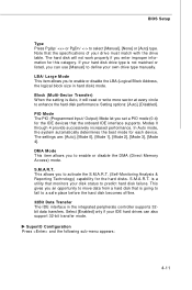
...] or [Auto] type. Note that monitors your own drive type manually. PIO Mode The PIO (Programmed Input/ Output) Mode let you can also support 32-bit transfer mode. If your hard disk drive type is a utility that the specifications of your IDE hard drives can use [Manual] to enable or disable the DMA (Direct Memory Access) mode. S.M.A.R.T. Select [Enabled] only if your drive must match with the drive table. is not matched or listed, you set a PIO mode (0-4) for each...
...] or [Auto] type. Note that monitors your own drive type manually. PIO Mode The PIO (Programmed Input/ Output) Mode let you can also support 32-bit transfer mode. If your hard disk drive type is a utility that the specifications of your IDE hard drives can use [Manual] to enable or disable the DMA (Direct Memory Access) mode. S.M.A.R.T. Select [Enabled] only if your drive must match with the drive table. is not matched or listed, you set a PIO mode (0-4) for each...
User Guide
Page 62
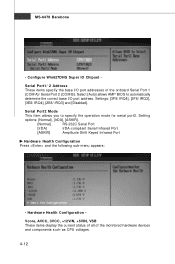
... display the current status of all of the onboard Serial Port 1 (COM A)/ Serial Port 2 (COM B). Setting options: [Normal], [IrDA], [ASKIR]. [Normal] RS-232C Serial Port [IrDA] IrDA-compliant Serial Infrared Port [ASKIR] Amplitude Shift Keyed Infrared Port Hardware Health Configuration Press and the following sub-menu appears: - Serial Port2 M ode This item allows you to automatically determine the correct base I /O port addresses of the monitored hardware devices and components such as CPU...
... display the current status of all of the onboard Serial Port 1 (COM A)/ Serial Port 2 (COM B). Setting options: [Normal], [IrDA], [ASKIR]. [Normal] RS-232C Serial Port [IrDA] IrDA-compliant Serial Infrared Port [ASKIR] Amplitude Shift Keyed Infrared Port Hardware Health Configuration Press and the following sub-menu appears: - Serial Port2 M ode This item allows you to automatically determine the correct base I /O port addresses of the monitored hardware devices and components such as CPU...
User Guide
Page 67
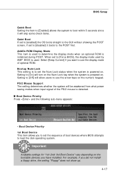
... the system is used . Setting to [Off] will skip some check items. Quiet Boot If set to [enabled] the OS boots straight to the GUI without showing the POST screen, if set the sequence of boot devices where BIOS attempts to load the disk operating system. AddOn ROM Display M ode This item is powered on the bootable devices you to set to [disabled] it will allow users to use the display mode of optional ROM.
... the system is used . Setting to [Off] will skip some check items. Quiet Boot If set to [enabled] the OS boots straight to the GUI without showing the POST screen, if set the sequence of boot devices where BIOS attempts to load the disk operating system. AddOn ROM Display M ode This item is powered on the bootable devices you to set to [disabled] it will allow users to use the display mode of optional ROM.

User Guide
Page 68
... Installed Change Supervisor Password Use this area is enabled and any attempt to the system at boot. Change User Password Use this item to change the user password that controls access to write data into this item to change the supervisor password that controls access to set the Virus W arning feature for IDE Hard Disk boot sector protection. Security Settings - MS-6478 Barebone Security - If the function is made, BIOS will display a warning message on screen and beep...
... Installed Change Supervisor Password Use this area is enabled and any attempt to the system at boot. Change User Password Use this item to change the user password that controls access to write data into this item to change the supervisor password that controls access to set the Virus W arning feature for IDE Hard Disk boot sector protection. Security Settings - MS-6478 Barebone Security - If the function is made, BIOS will display a warning message on screen and beep...
User Guide
Page 83
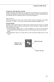
... audio field, Realtek HD Audio Sound Manager provides you certain optimized equalizer settings that are frequently used for your quick enjoyment. [How to Use It] Other than the buttons "Pop" "Live" "Club" & "Rock" shown on the page, to pull down the arrow in place, and you can help you eliminate the vocal of the song or adjust the key...
... audio field, Realtek HD Audio Sound Manager provides you certain optimized equalizer settings that are frequently used for your quick enjoyment. [How to Use It] Other than the buttons "Pop" "Live" "Club" & "Rock" shown on the page, to pull down the arrow in place, and you can help you eliminate the vocal of the song or adjust the key...
User Guide
Page 95
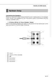
Realtek ALC888 Audio Hardware Setup Connecting the Speakers W hen you have set the Multi-Channel Audio Function mode properly in the software utility, connect your speakers to the following diagram and caption for Stereo-Speaker Output Refer to the correct phone jacks in accordance with the setting in software utility. n 2-Channel Mode for the function of each phone jack on the back panel when 2-Channel Mode is selected. 1 4 2 5 3 6 1 Line In 2 Line Out (Front channels) 3 MIC 4 No function 5 No function 6 No function A-19
Realtek ALC888 Audio Hardware Setup Connecting the Speakers W hen you have set the Multi-Channel Audio Function mode properly in the software utility, connect your speakers to the following diagram and caption for Stereo-Speaker Output Refer to the correct phone jacks in accordance with the setting in software utility. n 2-Channel Mode for the function of each phone jack on the back panel when 2-Channel Mode is selected. 1 4 2 5 3 6 1 Line In 2 Line Out (Front channels) 3 MIC 4 No function 5 No function 6 No function A-19


