User Guide
Page 9
... Processing Unit 2-3 Memory...2-6 Power Supply 2-7 Front Panel...2-8 Back Panel...2-9 Connectors...2-11 Jumper...2-16 Slot...2-17 Chapter 3. Getting Started 1-1 Mainboard Specifications 1-2 System Configuration 1-4 Thermal Solution 1-7 Chapter 2. BIOS Setup 4-1 Entering Setup 4-2 The Menu Bar 4-4 Main...4-6 Advanced...4-8 Boot...4-16 Security...4-18 Chipset...4-20 Power...4-24 Exit...4-25 Appendix A. Patent Numbers iii Revision History...iii...
... Processing Unit 2-3 Memory...2-6 Power Supply 2-7 Front Panel...2-8 Back Panel...2-9 Connectors...2-11 Jumper...2-16 Slot...2-17 Chapter 3. Getting Started 1-1 Mainboard Specifications 1-2 System Configuration 1-4 Thermal Solution 1-7 Chapter 2. BIOS Setup 4-1 Entering Setup 4-2 The Menu Bar 4-4 Main...4-6 Advanced...4-8 Boot...4-16 Security...4-18 Chipset...4-20 Power...4-24 Exit...4-25 Appendix A. Patent Numbers iii Revision History...iii...
User Guide
Page 34
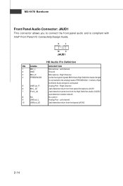
... Pin Definition PIN SIGNAL 1 MIC_L 2 GND 3 MIC_R 4 PRESENCE# 5 LINE out_R 6 MIC_JD 7 Front_JD 8 NC 9 LINE out_L 10 LINEout_JD DESCRIPTION Microphone - Right channel Active low signal-signals BIOS that a High Definition Audio dongle is connected to connect the front panel audio and is connected Analog Port - Right channel Jack detection return from front...
... Pin Definition PIN SIGNAL 1 MIC_L 2 GND 3 MIC_R 4 PRESENCE# 5 LINE out_R 6 MIC_JD 7 Front_JD 8 NC 9 LINE out_L 10 LINEout_JD DESCRIPTION Microphone - Right channel Active low signal-signals BIOS that a High Definition Audio dongle is connected to connect the front panel audio and is connected Analog Port - Right channel Jack detection return from front...
User Guide
Page 37
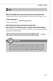
Meanwhile, read the documentation for the expansion card, such as jumpers, switches or BIOS configuration. 2-17 Mini-PCI Express Slot PCI (Peripheral Component Interconnect) Slot (No function for this model due to configure any necessary hardware or software settings ...
Meanwhile, read the documentation for the expansion card, such as jumpers, switches or BIOS configuration. 2-17 Mini-PCI Express Slot PCI (Peripheral Component Interconnect) Slot (No function for this model due to configure any necessary hardware or software settings ...
User Guide
Page 51
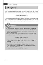
Chapter 4 BIOS Setup BIOS Setup This chapter provides the information on the screen during the system booting up, and requests you to configure the system for customized features. 4-1 You may need to run the Setup program when: An error message appears on the BIOS Setup program and allows you to change the default settings for optimum use. You want to run SETUP.
Chapter 4 BIOS Setup BIOS Setup This chapter provides the information on the screen during the system booting up, and requests you to configure the system for customized features. 4-1 You may need to run the Setup program when: An error message appears on the BIOS Setup program and allows you to change the default settings for optimum use. You want to run SETUP.
User Guide
Page 52
.... 111407 refers to enter Setup, restart the system by simultaneously pressing , , and keys. The items under each BIOS category described in the format: A7409IMS V1.0 011108 where: 1st digit refers to BIOS maker as A = AMI, W = AWARD, and P = PHOENIX. 2nd - 5th digit refers to the model number. 6th... N = nVidia, and V = VIA. 7th - 8th digit refers to the customer as MS = all standard customers. You may be slightly different from the latest BIOS and should be held for better system performance. W hen the message below appears on the computer and the system will start POST (Power On Self...
.... 111407 refers to enter Setup, restart the system by simultaneously pressing , , and keys. The items under each BIOS category described in the format: A7409IMS V1.0 011108 where: 1st digit refers to BIOS maker as A = AMI, W = AWARD, and P = PHOENIX. 2nd - 5th digit refers to the model number. 6th... N = nVidia, and V = VIA. 7th - 8th digit refers to the customer as MS = all standard customers. You may be slightly different from the latest BIOS and should be held for better system performance. W hen the message below appears on the computer and the system will start POST (Power On Self...
User Guide
Page 53
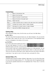
...for the highlighted item. You can be launched from a submenu Increase the numeric value or make changes Decrease the numeric value or make changes to. BIOS Setup Control Keys Move to the previous item Move to the next item Move to the item in the right hand Select the item Jumps...a sub-menu. Sub-Menu If you will see is displayed at the bottom of the highlighted setup function is the Main Menu. General Help The BIOS setup program provides a General Help screen. Main Menu The main menu lists the setup functions you want to return to exit the Help screen. 4-3
...for the highlighted item. You can be launched from a submenu Increase the numeric value or make changes Decrease the numeric value or make changes to. BIOS Setup Control Keys Move to the previous item Move to the next item Move to the item in the right hand Select the item Jumps...a sub-menu. Sub-Menu If you will see is displayed at the bottom of the highlighted setup function is the Main Menu. General Help The BIOS setup program provides a General Help screen. Main Menu The main menu lists the setup functions you want to return to exit the Help screen. 4-3

User Guide
Page 55
BIOS Setup Exit This menu allows you to load the BIOS default values or factory default settings into the BIOS and exit the BIOS setup utility with or without changes. 4-5
BIOS Setup Exit This menu allows you to load the BIOS default values or factory default settings into the BIOS and exit the BIOS setup utility with or without changes. 4-5
User Guide
Page 56
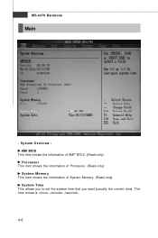
MS-6478 Barebone Main - The time format is . 4-6 System Overview AMI BIOS This item shows the information of AMI® BIOS. (Read-only) Processor This item shows the information of Processor. (Read-only) System Memory This item shows the information of System Memory. (Read-only) System Time This allows you to set the system time that you want (usually the current time).
MS-6478 Barebone Main - The time format is . 4-6 System Overview AMI BIOS This item shows the information of AMI® BIOS. (Read-only) Processor This item shows the information of Processor. (Read-only) System Memory This item shows the information of System Memory. (Read-only) System Time This allows you to set the system time that you want (usually the current time).
User Guide
Page 57
The date format is . [Day] Day of the week, from Sun to Sat, determined by BIOS. [Month] The month from 1 to set the system date that you want (usually the current date). BIOS Setup System Date This allows you to 31 can be keyed by numeric function keys. [ Ye ar ] The year can be adjusted by users. 4-7 through Dec. [Date] The date from Jan.
The date format is . [Day] Day of the week, from Sun to Sat, determined by BIOS. [Month] The month from 1 to set the system date that you want (usually the current date). BIOS Setup System Date This allows you to 31 can be keyed by numeric function keys. [ Ye ar ] The year can be adjusted by users. 4-7 through Dec. [Date] The date from Jan.
User Guide
Page 59
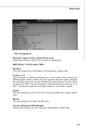
... the current status of the processor. (Read-only) Cache L1/ L2 Cache memory is additional memory that is much faster than conventional DRAM (system memory). BIOS Setup - This item shows the internal cache (also known as L1 or level 1 cache) and external cache (also known as L2 or level 2 cache). CPU...
... the current status of the processor. (Read-only) Cache L1/ L2 Cache memory is additional memory that is much faster than conventional DRAM (system memory). BIOS Setup - This item shows the internal cache (also known as L1 or level 1 cache) and external cache (also known as L2 or level 2 cache). CPU...
User Guide
Page 61
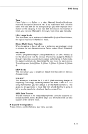
... must match with the drive table. Modes 0 through 4 provide successively increased performance. is a utility that is going to fail to enhance the hard disk performance. BIOS Setup Type Press PgUp/ or PgDn/ to enable or disable the LBA (Logical Block Address, the logical block size in the integrated peripherals controller supports...
... must match with the drive table. Modes 0 through 4 provide successively increased performance. is a utility that is going to fail to enhance the hard disk performance. BIOS Setup Type Press PgUp/ or PgDn/ to enable or disable the LBA (Logical Block Address, the logical block size in the integrated peripherals controller supports...
User Guide
Page 62
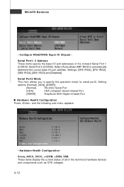
Select [Auto] allows AMI® BIOS to specify the operation mode for serial port2. Hardware Health Configuration Vcore, AVCC, 3VCC, +12VIN, +5VIN, VSB These items display the current status of all ...
Select [Auto] allows AMI® BIOS to specify the operation mode for serial port2. Hardware Health Configuration Vcore, AVCC, 3VCC, +12VIN, +5VIN, VSB These items display the current status of all ...
User Guide
Page 63
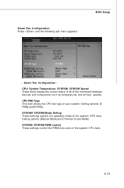
SYSFAN/ CPUFAN PWM Control These settings control the PWM duty cycle of your system. Smart Fan Configuration Press and the following sub-menu appears: BIOS Setup - CPU FAN Type This item shows the CPU fan type of the system/ CPU fans. 4-13 Setting options: [3 PINS] and [4 PINS]. SYSFAN/ CPUFAN Mode ...
SYSFAN/ CPUFAN PWM Control These settings control the PWM duty cycle of your system. Smart Fan Configuration Press and the following sub-menu appears: BIOS Setup - CPU FAN Type This item shows the CPU fan type of the system/ CPU fans. 4-13 Setting options: [3 PINS] and [4 PINS]. SYSFAN/ CPUFAN Mode ...
User Guide
Page 65
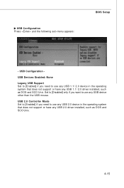
... [Enabled] if you want to use any USB 2.0 driver installed, such as DOS and SCO Unix. USB Configuration Press and the following sub-menu appears: BIOS Setup -
... [Enabled] if you want to use any USB 2.0 driver installed, such as DOS and SCO Unix. USB Configuration Press and the following sub-menu appears: BIOS Setup -
User Guide
Page 67
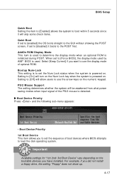
... PS/2 mouse is initialized during POST. Bootup Num-Lock This setting is to set to [Force BIOS], the display mode used . W hen set the Num Lock status when the system is used by AMI® BIOS is powered on the numeric keypad. Select [Keep Current] if you have installed. Boot Device Priority1st...] it will turn on the Num Lock key when the system is powered on the bootable devices you want to use the arrow keys on . BIOS Setup Quick Boot Setting the item to [Enabled] allows the system to boot within 5 seconds since it boots to the POST first. Setting to [Off...
... PS/2 mouse is initialized during POST. Bootup Num-Lock This setting is to set to [Force BIOS], the display mode used . W hen set the Num Lock status when the system is used by AMI® BIOS is powered on the numeric keypad. Select [Keep Current] if you have installed. Boot Device Priority1st...] it will turn on the Num Lock key when the system is powered on the bootable devices you want to use the arrow keys on . BIOS Setup Quick Boot Setting the item to [Enabled] allows the system to boot within 5 seconds since it boots to the POST first. Setting to [Off...

User Guide
Page 68
... display a warning message on screen and beep. 4-18 MS-6478 Barebone Security - Boot Sector Virus Protection The item is enabled and any attempt to the BIOS Setup utility. Supervisor Password User Password : Not Installed : Not Installed Change Supervisor Password Use this item to change the user password that controls access to...
... display a warning message on screen and beep. 4-18 MS-6478 Barebone Security - Boot Sector Virus Protection The item is enabled and any attempt to the BIOS Setup utility. Supervisor Password User Password : Not Installed : Not Installed Change Supervisor Password Use this item to change the user password that controls access to...
User Guide
Page 69
If you first disable the virus warning. 4-19 BIOS Setup Important Many disk diagnostic programs that you plan to run such a program, we recommend that access the boot sector table can trigger the virus warning message.
If you first disable the virus warning. 4-19 BIOS Setup Important Many disk diagnostic programs that you plan to run such a program, we recommend that access the boot sector table can trigger the virus warning message.
User Guide
Page 71
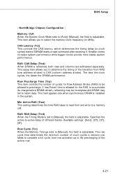
... delay of the transition from row activation up to retain data. RAS/ CAS Delay (Trcd) W hen DRAM is adjustable. Available settings: [Auto], [2T], [3T], [4T]. BIOS Setup -
... delay of the transition from row activation up to retain data. RAS/ CAS Delay (Trcd) W hen DRAM is adjustable. Available settings: [Auto], [2T], [3T], [4T]. BIOS Setup -
User Guide
Page 73
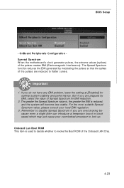
... creates EMI (Electromagnetic Interference). OnBoard Peripherals Configuration Spread Spectrum W hen the motherboard's clock generator pulses, the extreme values (spikes) of the Onboard LAN Chip. 4-23 BIOS Setup -
... creates EMI (Electromagnetic Interference). OnBoard Peripherals Configuration Spread Spectrum W hen the motherboard's clock generator pulses, the extreme values (spikes) of the Onboard LAN Chip. 4-23 BIOS Setup -
User Guide
Page 75
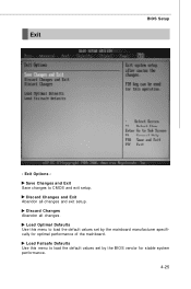
Discard Changes Abandon all changes and exit setup. Exit BIOS Setup - Discard Changes and Exit Abandon all changes. Load Failsafe Defaults Use this menu to load the default values set by the BIOS vendor for optimal performance of the mainboard. Exit Options - Load Optimal Defaults Use this menu to load the default values set by the mainboard manufacturer specifically for stable system performance. 4-25 Save Changes and Exit Save changes to CMOS and exit setup.
Discard Changes Abandon all changes and exit setup. Exit BIOS Setup - Discard Changes and Exit Abandon all changes. Load Failsafe Defaults Use this menu to load the default values set by the BIOS vendor for optimal performance of the mainboard. Exit Options - Load Optimal Defaults Use this menu to load the default values set by the mainboard manufacturer specifically for stable system performance. 4-25 Save Changes and Exit Save changes to CMOS and exit setup.
