
User Manual
Page 12
... M2_1: M.2 Slot (Key M 30 SATA1~6: SATA 6Gb/s Connectors 31 JFP1, JFP2: Front Panel Connectors 31 CPU_PWR1, ATX_PWR1: Power Connectors 32 JAUD1: Front Audio Connector 32 JUSB1~2: USB 2.0 Connectors 33 JUSB3: USB 3.2 Gen1 Connector 33 CPU_FAN1, PUMP_FAN1, SYS_FAN1~4: Fan Connectors 34 JCOM1: Serial Port Connector 34 JCI1: Chassis Intrusion Connector 35 JTPM1: TPM Module Connector 35 JLPT1: Parallel Port Connector 36 12 Contents
... M2_1: M.2 Slot (Key M 30 SATA1~6: SATA 6Gb/s Connectors 31 JFP1, JFP2: Front Panel Connectors 31 CPU_PWR1, ATX_PWR1: Power Connectors 32 JAUD1: Front Audio Connector 32 JUSB1~2: USB 2.0 Connectors 33 JUSB3: USB 3.2 Gen1 Connector 33 CPU_FAN1, PUMP_FAN1, SYS_FAN1~4: Fan Connectors 34 JCOM1: Serial Port Connector 34 JCI1: Chassis Intrusion Connector 35 JTPM1: TPM Module Connector 35 JLPT1: Parallel Port Connector 36 12 Contents
User Manual
Page 17
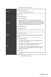
...RAID1 and RAID 10 for SATA storage devices y AMD® B450 Chipset ƒ 2x USB 3.2 Gen2 (SuperSpeed USB 10Gbps) Type-A ports on the back panel ƒ 2x USB 3.2 Gen1 (SuperSpeed USB) ports available through the internal USB 3.2 Gen1 connector ƒ 6x USB 2.0 (High-speed USB) ports (2 Type...-A ports on the back panel, 4 ports available through the internal USB 2.0 connectors) y AMD® CPU ƒ 2x ...
...RAID1 and RAID 10 for SATA storage devices y AMD® B450 Chipset ƒ 2x USB 3.2 Gen2 (SuperSpeed USB 10Gbps) Type-A ports on the back panel ƒ 2x USB 3.2 Gen1 (SuperSpeed USB) ports available through the internal USB 3.2 Gen1 connector ƒ 6x USB 2.0 (High-speed USB) ports (2 Type...-A ports on the back panel, 4 ports available through the internal USB 2.0 connectors) y AMD® CPU ƒ 2x ...
User Manual
Page 18
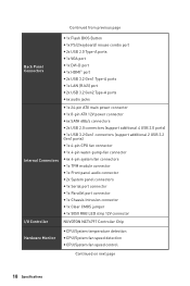
... 12V power connector y 6x SATA 6Gb/s connectors y 2x USB 2.0 connectors (support additional 4 USB 2.0 ports) y 1x USB 3.2 Gen1 connectors (support additional 2 USB 3.2 Gen1 ports) y 1x 4-pin CPU fan connector y 1x 4-pin water-pump-fan connector y 4x 4-pin system fan connectors y 1x TPM module connector y 1x Front panel audio connector y 2x System panel connectors y 1x Serial port connector y 1x Parallel port connector y 1x Chassis Intrusion connector y 1x...
... 12V power connector y 6x SATA 6Gb/s connectors y 2x USB 2.0 connectors (support additional 4 USB 2.0 ports) y 1x USB 3.2 Gen1 connectors (support additional 2 USB 3.2 Gen1 ports) y 1x 4-pin CPU fan connector y 1x 4-pin water-pump-fan connector y 4x 4-pin system fan connectors y 1x TPM module connector y 1x Front panel audio connector y 2x System panel connectors y 1x Serial port connector y 1x Parallel port connector y 1x Chassis Intrusion connector y 1x...

User Manual
Page 26
..., DIMMB2 DIMM Slots 28 JAUD1 Front Audio Connector 32 JBAT1 Clear CMOS Jumper 36 JCI1 Chassis Intrusion Connector 35 JCOM1 Serial Port Connector 34 JFP1, JFP2 Front Panel Connectors 31 JLPT1 Parallel Port Connector 36 JRGB1 RGB LED connectors 37 JTPM1 TPM Module Connector 35 JUSB1~2 USB 2.0 Connectors 33 JUSB3 USB 3.2 Gen1 Connector 33 M2_1 M.2 Slot (Key M) 30 PCI_E1~6 PCIe...
..., DIMMB2 DIMM Slots 28 JAUD1 Front Audio Connector 32 JBAT1 Clear CMOS Jumper 36 JCI1 Chassis Intrusion Connector 35 JCOM1 Serial Port Connector 34 JFP1, JFP2 Front Panel Connectors 31 JLPT1 Parallel Port Connector 36 JRGB1 RGB LED connectors 37 JTPM1 TPM Module Connector 35 JUSB1~2 USB 2.0 Connectors 33 JUSB3 USB 3.2 Gen1 Connector 33 M2_1 M.2 Slot (Key M) 30 PCI_E1~6 PCIe...
User Manual
Page 31
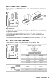
... cables have identical plugs on the front panel. SATA1 SATA2 SATA6 SATA5 SATA4 SATA3 Important y Please do not fold the SATA cable at a 90-degree angle. SATA1~6: SATA 6Gb/s Connectors These connectors are SATA 6Gb/s interface ports. JFP1, JFP2: Front Panel Connectors These connectors connect to one SATA device. Each connector can connect to the switches and...
... cables have identical plugs on the front panel. SATA1 SATA2 SATA6 SATA5 SATA4 SATA3 Important y Please do not fold the SATA cable at a 90-degree angle. SATA1~6: SATA 6Gb/s Connectors These connectors are SATA 6Gb/s interface ports. JFP1, JFP2: Front Panel Connectors These connectors connect to one SATA device. Each connector can connect to the switches and...
User Manual
Page 32
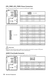
JAUD1: Front Audio Connector This connector allows you to connect an ATX power supply. 8 5 CPU_PWR1 4 1 1 Ground 5 2 Ground 6 3 Ground 7 4 Ground 8 +12V +12V +12V +12V 1 +3.3V 13 2 +3.3V 14 3 Ground 15 12 24 4 ... +5V Ground Important Make sure that all the power cables are securely connected to a proper ATX power supply to connect audio jacks on the front panel. 2 10 1 9 1 MIC L 2 Ground 3 MIC R 4 NC 5 Head Phone R 6 MIC Detection 7 SENSE_SEND 8 No Pin 9 Head Phone L 10 Head Phone Detection 32 Overview of the motherboard. CPU_PWR1, ...
JAUD1: Front Audio Connector This connector allows you to connect an ATX power supply. 8 5 CPU_PWR1 4 1 1 Ground 5 2 Ground 6 3 Ground 7 4 Ground 8 +12V +12V +12V +12V 1 +3.3V 13 2 +3.3V 14 3 Ground 15 12 24 4 ... +5V Ground Important Make sure that all the power cables are securely connected to a proper ATX power supply to connect audio jacks on the front panel. 2 10 1 9 1 MIC L 2 Ground 3 MIC R 4 NC 5 Head Phone R 6 MIC Detection 7 SENSE_SEND 8 No Pin 9 Head Phone L 10 Head Phone Detection 32 Overview of the motherboard. CPU_PWR1, ...
User Manual
Page 33
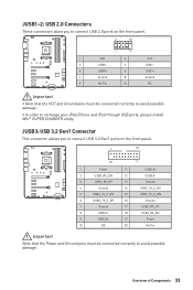
y In order to recharge your iPad,iPhone and iPod through USB ports, please install MSI® SUPER CHARGER utility. JUSB3: USB 3.2 Gen1 Connector This connector allows you to connect USB 2.0 ports on the front panel. 1 10 20 11 1 Power 11 2 USB3_RX_DN 12 3 USB3_RX_DP 13 4 Ground 14 5 ...No Pin Important Note that the VCC and Ground pins must be connected correctly to avoid possible damage. JUSB1~2: USB 2.0 Connectors These connectors allow you to connect USB 3.2 Gen1 ports on the front panel. 2 10 1 9 1 VCC 2 3 USB0- 4 5 USB0+ 6 7 Ground 8 9 No Pin 10...
y In order to recharge your iPad,iPhone and iPod through USB ports, please install MSI® SUPER CHARGER utility. JUSB3: USB 3.2 Gen1 Connector This connector allows you to connect USB 2.0 ports on the front panel. 1 10 20 11 1 Power 11 2 USB3_RX_DN 12 3 USB3_RX_DP 13 4 Ground 14 5 ...No Pin Important Note that the VCC and Ground pins must be connected correctly to avoid possible damage. JUSB1~2: USB 2.0 Connectors These connectors allow you to connect USB 3.2 Gen1 ports on the front panel. 2 10 1 9 1 VCC 2 3 USB0- 4 5 USB0+ 6 7 Ground 8 9 No Pin 10...

User Manual
Page 92
...over troubleshooting guide first to the motherboard? y Select different inputs on . y If 3 long beeps are heard, remove all ATX power connectors like ATX_PWR1, CPU_PWR1 are connected from the power supply to see if your USB drive driver has been installed. y Remove secondary speakers/ ... USB audio devices. y Restart or reset your TCP/IP settings. y Connect the USB device to audio ports on the motherboard rear IO panel. y Test with another known working power supply of equal or greater wattage. y Test with another known working graphics card. Lost BIOS password...
...over troubleshooting guide first to the motherboard? y Select different inputs on . y If 3 long beeps are heard, remove all ATX power connectors like ATX_PWR1, CPU_PWR1 are connected from the power supply to see if your USB drive driver has been installed. y Remove secondary speakers/ ... USB audio devices. y Restart or reset your TCP/IP settings. y Connect the USB device to audio ports on the motherboard rear IO panel. y Test with another known working power supply of equal or greater wattage. y Test with another known working graphics card. Lost BIOS password...


