User Guide
Page 2
... guidance. ◙ Visit the MSI website for PCB 1.X Date November 2009 Technical Support If a problem arises with your system and no guarantee is given as to make changes without notice. Revision History Revision V1.0 Revision History First release for FAQ, technical guide, BIOS updates, driver updates, and other information: http://www.msi.com/index.php?func=service ◙ Contact our technical...
... guidance. ◙ Visit the MSI website for PCB 1.X Date November 2009 Technical Support If a problem arises with your system and no guarantee is given as to make changes without notice. Revision History Revision V1.0 Revision History First release for FAQ, technical guide, BIOS updates, driver updates, and other information: http://www.msi.com/index.php?func=service ◙ Contact our technical...

User Guide
Page 8
... Getting Started 1-1 Mainboard Specifications 1-2 Mainboard Layout 1-4 Packing Checklist 1-5 Chapter 2 Hardware Setup 2-1 Quick Components Guide 2-2 CPU (Central Processing Unit 2-3 Memory 2-7 Power Supply 2-9 Back Panel 2-10 Connectors 2-12 Jumpers 2-18 Slots 2-20 LED Status Indicators 2-21 Chapter 3 BIOS Setup 3-1 Entering Setup 3-2 The Main Menu 3-4 Standard CMOS Features 3-6 Advanced BIOS Features 3-8 Integrated Peripherals 3-10 Power Management Setup 3-12 H/W Monitor 3-14 Green Power 3-15 BIOS Setting Password 3-16 Cell Menu 3-17 M-Flash 3-25 Overclocking Profile...
... Getting Started 1-1 Mainboard Specifications 1-2 Mainboard Layout 1-4 Packing Checklist 1-5 Chapter 2 Hardware Setup 2-1 Quick Components Guide 2-2 CPU (Central Processing Unit 2-3 Memory 2-7 Power Supply 2-9 Back Panel 2-10 Connectors 2-12 Jumpers 2-18 Slots 2-20 LED Status Indicators 2-21 Chapter 3 BIOS Setup 3-1 Entering Setup 3-2 The Main Menu 3-4 Standard CMOS Features 3-6 Advanced BIOS Features 3-8 Integrated Peripherals 3-10 Power Management Setup 3-12 H/W Monitor 3-14 Green Power 3-15 BIOS Setting Password 3-16 Cell Menu 3-17 M-Flash 3-25 Overclocking Profile...

User Guide
Page 12
... Spec IDE (optional) ■ 1 IDE port by JMicron® JMB368 ■ Supports Ultra DMA 100/133 mode ■ Supports PIO, Bus Master operation mode SATA ■ 6 SATA 3Gb/s (SATA1~6) ports by Intel® H55 Connectors ■ Back panel - 1 PS/2 keyboard port - 1 PS/2 mouse port - 6 USB 2.0 ports - 1 HDMI port* (optional) - 1 VGA port* - 1 DVI port* (optional) - 1 LAN port - 6 flexible audio ports (for H55M-E33) - 3 flexible audio ports (for H55M-P31) *(The HDMI, VGA and DVI ports only work with Integrated Graphics Processor) ■ On-Board - 3 USB 2.0 connectors - 1 Chassis Intrusion...
... Spec IDE (optional) ■ 1 IDE port by JMicron® JMB368 ■ Supports Ultra DMA 100/133 mode ■ Supports PIO, Bus Master operation mode SATA ■ 6 SATA 3Gb/s (SATA1~6) ports by Intel® H55 Connectors ■ Back panel - 1 PS/2 keyboard port - 1 PS/2 mouse port - 6 USB 2.0 ports - 1 HDMI port* (optional) - 1 VGA port* - 1 DVI port* (optional) - 1 LAN port - 6 flexible audio ports (for H55M-E33) - 3 flexible audio ports (for H55M-P31) *(The HDMI, VGA and DVI ports only work with Integrated Graphics Processor) ■ On-Board - 3 USB 2.0 connectors - 1 Chassis Intrusion...

User Guide
Page 19
... specifications. For the latest information about CPU, please visit http://www.msi.com/index. Replacing the CPU While replacing the CPU, always turn off the ATX power supply or unplug the power supply's power cord from overheating. We do not have the CPU cooler, consult your components are installing the CPU, make sure your dealer before turning on it for better heat dispersion. Alignment Key Yellow triangle is the Pin...
... specifications. For the latest information about CPU, please visit http://www.msi.com/index. Replacing the CPU While replacing the CPU, always turn off the ATX power supply or unplug the power supply's power cord from overheating. We do not have the CPU cooler, consult your components are installing the CPU, make sure your dealer before turning on it for better heat dispersion. Alignment Key Yellow triangle is the Pin...
User Guide
Page 25
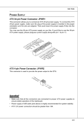
... (and above) is highly recommended for system stability. • ATX 12V power connection should be greater than 18A. 2-9 MS-7636 Power Supply ATX 24-pin Power Connector: JPWR1 This connector allows you like to use the 20-pin ATX power supply as you to ensure stable operation of the mainboard. • Power supply of the power supply is inserted in the proper orientation and the pins are connected to proper ATX power supplies to connect an ATX 24-pin power supply.
... (and above) is highly recommended for system stability. • ATX 12V power connection should be greater than 18A. 2-9 MS-7636 Power Supply ATX 24-pin Power Connector: JPWR1 This connector allows you like to use the 20-pin ATX power supply as you to ensure stable operation of the mainboard. • Power supply of the power supply is inserted in the proper orientation and the pins are connected to proper ATX power supplies to connect an ATX 24-pin power supply.

User Guide
Page 27
... high-definition video, plus multi-channel digital audio on the mainboard are used for external CD player, tape-player or other end of the cable is a connector for speakers or headphones. ■ Mic: Pink - Important To reach the 8-channel sound effect, the 7th and 8th channels must be output from front panel if you installed a processor without integrated graphics chip, these display ports will have no effect. ▶ Audio Ports These audio connectors...
... high-definition video, plus multi-channel digital audio on the mainboard are used for external CD player, tape-player or other end of the cable is a connector for speakers or headphones. ■ Mic: Pink - Important To reach the 8-channel sound effect, the 7th and 8th channels must be output from front panel if you installed a processor without integrated graphics chip, these display ports will have no effect. ▶ Audio Ports These audio connectors...

User Guide
Page 28
...on the same cable, you must configure the drives separately to master / slave mode by the vendors for jumper setting instructions. To clear the warning, you must enter the BIOS utility and clear the record. 1.C2.IGNTroRuUnd 2-12 The system will be activated. Refer to the chassis intrusion switch cable. Chassis Intrusion Connector: JCI1 This connector connects to IDE device's documentation supplied by setting jumpers. ▍ Hardware Setup Connectors IDE Connector: IDE1 (optional) This connector supports IDE hard disk drives, optical disk drives and other IDE devices.
...on the same cable, you must configure the drives separately to master / slave mode by the vendors for jumper setting instructions. To clear the warning, you must enter the BIOS utility and clear the record. 1.C2.IGNTroRuUnd 2-12 The system will be activated. Refer to the chassis intrusion switch cable. Chassis Intrusion Connector: JCI1 This connector connects to IDE device's documentation supplied by setting jumpers. ▍ Hardware Setup Connectors IDE Connector: IDE1 (optional) This connector supports IDE hard disk drives, optical disk drives and other IDE devices.
User Guide
Page 30
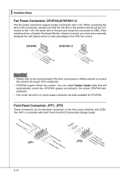
... 3 or 4 pins power connector are for electrical connection to the front panel switches and LEDs. The JFP1 is Ground and should be connected to GND. ▍ Hardware Setup Fan Power Connectors: CPUFAN,SYSFAN1~2 The fan power connectors support system cooling fan with speed sensor to take advantage of the CPU fan control. When connecting the wire to the connectors, always note that will automatically control the CPUFAN speeds according to the actual CPUFAN temperatures. • Fan cooler set with...
... 3 or 4 pins power connector are for electrical connection to the front panel switches and LEDs. The JFP1 is Ground and should be connected to GND. ▍ Hardware Setup Fan Power Connectors: CPUFAN,SYSFAN1~2 The fan power connectors support system cooling fan with speed sensor to take advantage of the CPU fan control. When connecting the wire to the connectors, always note that will automatically control the CPUFAN speeds according to the actual CPUFAN temperatures. • Fan cooler set with...
User Guide
Page 34
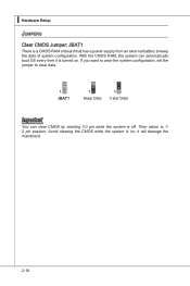
With the CMOS RAM, the system can clear CMOS by shorting 2-3 pin while the system is on . Avoid clearing the CMOS while the system is off. If you want to clear the system configuration, set the jumper to 12 pin position. Then return to clear data. 1 JBAT1 1 Keep Data 1 Clear Data Important You can automatically boot OS every time it will damage the mainboard. 2-18 ▍ Hardware Setup Jumpers Clear CMOS Jumper: JBAT1 There is turned on ; it is a CMOS RAM onboard that has a power supply from an external battery to keep the data of system configuration.
With the CMOS RAM, the system can clear CMOS by shorting 2-3 pin while the system is on . Avoid clearing the CMOS while the system is off. If you want to clear the system configuration, set the jumper to 12 pin position. Then return to clear data. 1 JBAT1 1 Keep Data 1 Clear Data Important You can automatically boot OS every time it will damage the mainboard. 2-18 ▍ Hardware Setup Jumpers Clear CMOS Jumper: JBAT1 There is turned on ; it is a CMOS RAM onboard that has a power supply from an external battery to keep the data of system configuration.
User Guide
Page 36
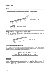
... line and pronounced I-R-Q, are typically connected to the microprocessor. ▍ Hardware Setup Slots PCIE (Peripheral Component Interconnect Express) Slot The PCI Express slot supports the PCI Express interface expansion card. PCI Express x16 Slot PCI Express x1 Slot PCI (Peripheral Component Interconnect) Slot The PCI slot supports LAN card, SCSI card, USB card, and other add-on cards that you unplug the power supply first. The PCI IRQ pins are hardware lines over which devices can send interrupt signals to the PCI bus pins as jumpers, switches or BIOS configuration. 2-20
... line and pronounced I-R-Q, are typically connected to the microprocessor. ▍ Hardware Setup Slots PCIE (Peripheral Component Interconnect Express) Slot The PCI Express slot supports the PCI Express interface expansion card. PCI Express x16 Slot PCI Express x1 Slot PCI (Peripheral Component Interconnect) Slot The PCI slot supports LAN card, SCSI card, USB card, and other add-on cards that you unplug the power supply first. The PCI IRQ pins are hardware lines over which devices can send interrupt signals to the PCI bus pins as jumpers, switches or BIOS configuration. 2-20
User Guide
Page 46
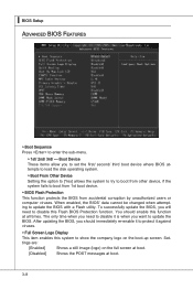
... BIOS from accidental corruption by unauthorized users or computer viruses. Set- ▍ BIOS Setup Advanced BIOS Features ▶ Boot Sequence Press to update the BIOS with a Flash utility. When enabled, the BIOS' data cannot be changed when attempting to enter the sub-menu. ▶ 1st/ 2nd/ 3rd/ --- To successfully update the BIOS, you to set the first/ second/ third boot device where BIOS attempts to load the disk operating system. ▶ Boot From Other Device Setting the option...
... BIOS from accidental corruption by unauthorized users or computer viruses. Set- ▍ BIOS Setup Advanced BIOS Features ▶ Boot Sequence Press to update the BIOS with a Flash utility. When enabled, the BIOS' data cannot be changed when attempting to enter the sub-menu. ▶ 1st/ 2nd/ 3rd/ --- To successfully update the BIOS, you to set the first/ second/ third boot device where BIOS attempts to load the disk operating system. ▶ Boot From Other Device Setting the option...
User Guide
Page 47
... PCI device can to enable it, and will provide you to select which graphic card is used for the graphics core.. [Fixed Mode] a fixed-size fragment of the system memory is powered on the numeric keypad. ▶ IOAPIC Function This field is your operating system. Setting to [On] will turn on . You need to select the MPS version supported by the graphics core. [DVMT Mode] the driver of the graphics core uses the...
... PCI device can to enable it, and will provide you to select which graphic card is used for the graphics core.. [Fixed Mode] a fixed-size fragment of the system memory is powered on the numeric keypad. ▶ IOAPIC Function This field is your operating system. Setting to [On] will turn on . You need to select the MPS version supported by the graphics core. [DVMT Mode] the driver of the graphics core uses the...

User Guide
Page 48
...onboard USB controller. ▶ USB Device Legacy Support Select [Enabled] if you need to use a USB-interfaced device in the operating system. ▶ Onboard LAN Controller This setting allows you to enable/disable the onboard LAN controller. ▶ LAN Option ROM This item is used to decide whether to invoke the Boot ROM of the onboard LAN. ▶ Extra RAID/ IDE Controller This item allows you to enable/disable the onboard extra RAID/ IDE controller. ▶ HD Audio Controller This setting is used to enable/disable the onboard audio controller. ▶ On-Chip ATA Devices Press to enter...
...onboard USB controller. ▶ USB Device Legacy Support Select [Enabled] if you need to use a USB-interfaced device in the operating system. ▶ Onboard LAN Controller This setting allows you to enable/disable the onboard LAN controller. ▶ LAN Option ROM This item is used to decide whether to invoke the Boot ROM of the onboard LAN. ▶ Extra RAID/ IDE Controller This item allows you to enable/disable the onboard extra RAID/ IDE controller. ▶ HD Audio Controller This setting is used to enable/disable the onboard audio controller. ▶ On-Chip ATA Devices Press to enter...
User Guide
Page 49
... support both the ECP and EPP modes simultaneously. 3-11 MS-7636 ▶ PCI IDE BusMaster This item allows you to enable/ disable BIOS to used PCI busmastering for reading/ writing to IDE drives. ▶ On-Chip SATA Controller This item allows users to enable or disable the on-chip SATA controller. ▶ RAID Mode This item is used to select mode for the serial port. ▶ Parallel Port There is a built-in parallel port on the on -chip SATA connectors. ▶ I /O chipset...
... support both the ECP and EPP modes simultaneously. 3-11 MS-7636 ▶ PCI IDE BusMaster This item allows you to enable/ disable BIOS to used PCI busmastering for reading/ writing to IDE drives. ▶ On-Chip SATA Controller This item allows users to enable or disable the on-chip SATA controller. ▶ RAID Mode This item is used to select mode for the serial port. ▶ Parallel Port There is a built-in parallel port on the on -chip SATA connectors. ▶ I /O chipset...

User Guide
Page 50
... supports ACPI, such as Windows 98SE/ 2000/ ME/ XP, select [Enabled]. ▶ ACPI Standby State This item specifies the power saving modes for ACPI function. nents turn off to main memory that remains powered while most other hardware compo- The information stored in memory will be used to restore the system when a "wake up" event occurs. ▶ ErP 2013 This item is used to enter the Standby mode...
... supports ACPI, such as Windows 98SE/ 2000/ ME/ XP, select [Enabled]. ▶ ACPI Standby State This item specifies the power saving modes for ACPI function. nents turn off to main memory that remains powered while most other hardware compo- The information stored in memory will be used to restore the system when a "wake up" event occurs. ▶ ErP 2013 This item is used to enter the Standby mode...
User Guide
Page 51
... USB Device The item allows the activity of the USB device to wake up the system from S3 (Suspend to RAM) sleep state. ▶ Resume From S3 By PS/2 Keyboard / Mouse These items determine whether the system will be awakened from what power saving modes when input signal of the PS/2 keyboard/ mouse is detected. ▶ Resume By PCI Device (PME#) When set to [Enabled...
... USB Device The item allows the activity of the USB device to wake up the system from S3 (Suspend to RAM) sleep state. ▶ Resume From S3 By PS/2 Keyboard / Mouse These items determine whether the system will be awakened from what power saving modes when input signal of the PS/2 keyboard/ mouse is detected. ▶ Resume By PCI Device (PME#) When set to [Enabled...
User Guide
Page 52
...; BIOS Setup H/W Monitor ▶ Chassis Intrusion The field enables or disables the feature of the field will automatically return to [Enabled] later. ▶ CPU Smart FAN Target The mainboard provides the Smart Fan function which can enable a fan target value here. The setting of recording the chassis intrusion status and issuing a warning message if the chassis is once opened. This item allows users to select the percentage of minimum speed...
...; BIOS Setup H/W Monitor ▶ Chassis Intrusion The field enables or disables the feature of the field will automatically return to [Enabled] later. ▶ CPU Smart FAN Target The mainboard provides the Smart Fan function which can enable a fan target value here. The setting of recording the chassis intrusion status and issuing a warning message if the chassis is once opened. This item allows users to select the percentage of minimum speed...

User Guide
Page 58
... CPU by the SPD (Serial Presence Detect) EE- 3-20 The system will be enabled after you set the overclocking frequency in MHz). The sub-menu displays the informations of installed memory. ▶ Current DRAM Channel1~4 Timing It shows the installed DRAM Timing. This field will appear. Read-only. ▶ Auto OverClock Technology This item is used to enable/ disable the Auto OverClock function. ▶ Memory-Z Press to enter the sub-menu. And the following screen...
... CPU by the SPD (Serial Presence Detect) EE- 3-20 The system will be enabled after you set the overclocking frequency in MHz). The sub-menu displays the informations of installed memory. ▶ Current DRAM Channel1~4 Timing It shows the installed DRAM Timing. This field will appear. Read-only. ▶ Auto OverClock Technology This item is used to enable/ disable the Auto OverClock function. ▶ Memory-Z Press to enter the sub-menu. And the following screen...

User Guide
Page 60
▍ BIOS Setup tsrWrTRd/ tddWrTWr/ tsrRDTRd/ tsrWrTWr These item show the advanced DRAM timings. ▶ Channel 1/ Channel2 Advanced Memory Setting Setting to [Auto] enables the advance memory timing automatically to flatter curves. But if you are used to select the CPU/ PCI Express clock amplitude. ▶ Adjust PCI-E Frequency (MHz) This field allows you do not have any EMI problem, leave the setting at [Disabled] for EMI reduction. • The greater...
▍ BIOS Setup tsrWrTRd/ tddWrTWr/ tsrRDTRd/ tsrWrTWr These item show the advanced DRAM timings. ▶ Channel 1/ Channel2 Advanced Memory Setting Setting to [Auto] enables the advance memory timing automatically to flatter curves. But if you are used to select the CPU/ PCI Express clock amplitude. ▶ Adjust PCI-E Frequency (MHz) This field allows you do not have any EMI problem, leave the setting at [Disabled] for EMI reduction. • The greater...

User Guide
Page 65
... the USB drive/ storage drive. Use this item to select particular BIOS file from the USB/ Storage (FAT/32 format only) drive. == Backup BIOS to USB drive == The following fields are used to read the onboard BIOS ROM data, and save it only supports FAT/ FAT32 file system drive. ▶ Save File Name as Please setup a specific extend name for booting. ▶ Load BIOS source file from When the M-Flash function as default name. ▶ Start to save BIOS file from the USB/ Storage...
... the USB drive/ storage drive. Use this item to select particular BIOS file from the USB/ Storage (FAT/32 format only) drive. == Backup BIOS to USB drive == The following fields are used to read the onboard BIOS ROM data, and save it only supports FAT/ FAT32 file system drive. ▶ Save File Name as Please setup a specific extend name for booting. ▶ Load BIOS source file from When the M-Flash function as default name. ▶ Start to save BIOS file from the USB/ Storage...


