
User Guide
Page 5
... Specifications 1-2 1.2 System Configuration 1-4 1.3 Thermal Solution 1-10 Chapter 2. Introducing Mainboard 2-1 2.1 Mainboard Layout 2-2 2.2 CPU 2-4 Introduction to LGA 775 CPU 2-4 CPU & Cooler Installation 2-5 2.3 Memory 2-8 Introduction to DDR SDRAM 2-8 DIMM Module Combination 2-9 Installing DDR Modules 2-9 2.4 Power Supply 2-10 ATX 20-Pin Power Connector: ATX1 2-10 ATX 12V Power Connector: JPW1 2-10 2.5 Front Panel 2-11 Audio Ports 2-11 USB Ports 2-11 IEEE 1394 Port (Standard only 2-11 2.6 Rear Panel 2-12 Mouse/Keyboard Connectors 2-12 Audio Port Connectors 2-13 VGA...
... Specifications 1-2 1.2 System Configuration 1-4 1.3 Thermal Solution 1-10 Chapter 2. Introducing Mainboard 2-1 2.1 Mainboard Layout 2-2 2.2 CPU 2-4 Introduction to LGA 775 CPU 2-4 CPU & Cooler Installation 2-5 2.3 Memory 2-8 Introduction to DDR SDRAM 2-8 DIMM Module Combination 2-9 Installing DDR Modules 2-9 2.4 Power Supply 2-10 ATX 20-Pin Power Connector: ATX1 2-10 ATX 12V Power Connector: JPW1 2-10 2.5 Front Panel 2-11 Audio Ports 2-11 USB Ports 2-11 IEEE 1394 Port (Standard only 2-11 2.6 Rear Panel 2-12 Mouse/Keyboard Connectors 2-12 Audio Port Connectors 2-13 VGA...

User Guide
Page 6
... HDD 3-5 3. Restoring Chassis Cover & Installing Footstand 3-11 Chapter 4. BIOS Setup 4-1 Entering Setup 4-2 Selecting the First Boot Device 4-2 Control Keys 4-3 Getting Help 4-3 Main Menu 4-3 Default Settings 4-3 The Main Menu 4-4 Standard CMOS Features 4-6 Advanced BIOS Features 4-8 Advanced Chipset Features 4-10 Integrated Peripherals 4-11 Power Management Features 4-14 PNP/PCI Configurations 4-17 H/W Monitor 4-18 vi Installing CPU 3-9 7. Installing Optical Drive 3-6 4. Fan Power Connectors: CPU_F2/CPU_F3 2-19 Front Panel Connectors: JFP1 2-20 CD-in Connector...
... HDD 3-5 3. Restoring Chassis Cover & Installing Footstand 3-11 Chapter 4. BIOS Setup 4-1 Entering Setup 4-2 Selecting the First Boot Device 4-2 Control Keys 4-3 Getting Help 4-3 Main Menu 4-3 Default Settings 4-3 The Main Menu 4-4 Standard CMOS Features 4-6 Advanced BIOS Features 4-8 Advanced Chipset Features 4-10 Integrated Peripherals 4-11 Power Management Features 4-14 PNP/PCI Configurations 4-17 H/W Monitor 4-18 vi Installing CPU 3-9 7. Installing Optical Drive 3-6 4. Fan Power Connectors: CPU_F2/CPU_F3 2-19 Front Panel Connectors: JFP1 2-20 CD-in Connector...

User Guide
Page 7
Introduction to Realtek ALC880 5-1 Installing the Realtek HD Audio Driver 5-2 Installation for Windows 2000/XP 5-2 Software Configuration 5-4 Sound Effect 5-5 Audio IO 5-6 Mixer 5-9 Microphone 5-12 3D Audio Demo 5-13 Information 5-14 Using 2-, 4-, 6- & 8- Channel Audio Function 5-15 vii BIOS Setting Password 4-19 Load Fail-Safe/Optimized Defaults 4-20 Chapter 5.
Introduction to Realtek ALC880 5-1 Installing the Realtek HD Audio Driver 5-2 Installation for Windows 2000/XP 5-2 Software Configuration 5-4 Sound Effect 5-5 Audio IO 5-6 Mixer 5-9 Microphone 5-12 3D Audio Demo 5-13 Information 5-14 Using 2-, 4-, 6- & 8- Channel Audio Function 5-15 vii BIOS Setting Password 4-19 Load Fail-Safe/Optimized Defaults 4-20 Chapter 5.
User Guide
Page 9
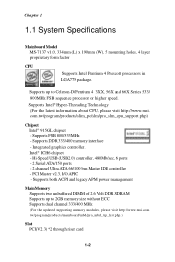
...; Supports dual channel 333/400 MHz (For the updated supporting memory modules, please visit http://www.msi.com. PCI Master v2.3, I/O APIC - tw/p ro gr a m /pr od u c ts/main bo a r d/ mb d/p ro _ mbd _ t rp_ li st .p hp .) Slot † PCI(V2.3) *2 through riser card 1-2 Hi-Speed USB (USB2.0) controller, 480Mb/sec, 6 ports - 2 Serial ATA/150 ports - 2 channel Ultra ATA 66/100 bus Master IDE controller - Integrated graphics controller. †...
...; Supports dual channel 333/400 MHz (For the updated supporting memory modules, please visit http://www.msi.com. PCI Master v2.3, I/O APIC - tw/p ro gr a m /pr od u c ts/main bo a r d/ mb d/p ro _ mbd _ t rp_ li st .p hp .) Slot † PCI(V2.3) *2 through riser card 1-2 Hi-Speed USB (USB2.0) controller, 480Mb/sec, 6 ports - 2 Serial ATA/150 ports - 2 channel Ultra ATA 66/100 bus Master IDE controller - Integrated graphics controller. †...
User Guide
Page 23
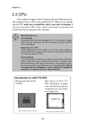
However, please make sure your dealer to support overclocking. Overclocking This motherboard is the Pin 1 indicator 2-4 Al i g nme n t Alignment Key Yellow triangle is the Pin 1 indicator Yellow triangle is designed to purchase and install them before turning on it for better heat dispersion. MSI Reminds You... Replacing the CPU While replacing the CPU, always turn off the power supply or unplug the power supply's power cord from overheating. Remember to...
However, please make sure your dealer to support overclocking. Overclocking This motherboard is the Pin 1 indicator 2-4 Al i g nme n t Alignment Key Yellow triangle is the Pin 1 indicator Yellow triangle is designed to purchase and install them before turning on it for better heat dispersion. MSI Reminds You... Replacing the CPU While replacing the CPU, always turn off the power supply or unplug the power supply's power cord from overheating. Remember to...

User Guide
Page 33
... and its display device. Data2+ 3 T.M.D.S. Data2/4 Shield 4 T.M.D.S. Data110 T.M.D.S. Data0/5 Shield 20 T.M.D.S. Clock Shield 23 T.M.D.S. Clock- *T.M.D.S. Data521 T.M.D.S. TMDS uses an enco di ng algorith m to your monitor. (refer to 8-bit s of the cable is properly connected to your monitor manual for tran smissio n over fi ber opti c cables. To connect a LCD monitor, simply plug your monitor cable into the DVI connector on the mainboard, and make sure...
... and its display device. Data2+ 3 T.M.D.S. Data2/4 Shield 4 T.M.D.S. Data110 T.M.D.S. Data0/5 Shield 20 T.M.D.S. Clock Shield 23 T.M.D.S. Clock- *T.M.D.S. Data521 T.M.D.S. TMDS uses an enco di ng algorith m to your monitor. (refer to 8-bit s of the cable is properly connected to your monitor manual for tran smissio n over fi ber opti c cables. To connect a LCD monitor, simply plug your monitor cable into the DVI connector on the mainboard, and make sure...

User Guide
Page 34
...-bit LAN enables data to single Local Area Network (LAN). You can connect a network cable to it. 8 1 RJ-45 LAN Jack Giga-bit LAN Pin Definition PIN SIGNAL 1 D0P 2 D0N 3 D1P 4 D2P 5 D2N 6 D1N 7 D3P 8 D3N DESCRIPTION Differential Pair 0+ Differential Pair 0Differential Pair 1+ Differential Pair 2+ Differential Pair 2Differential Pair 1Differential Pair 3+ Differential Pair 3- USB Ports The mainboard provides a UHCI (Universal Host Controller Interface) Universal Serial...
...-bit LAN enables data to single Local Area Network (LAN). You can connect a network cable to it. 8 1 RJ-45 LAN Jack Giga-bit LAN Pin Definition PIN SIGNAL 1 D0P 2 D0N 3 D1P 4 D2P 5 D2N 6 D1N 7 D3P 8 D3N DESCRIPTION Differential Pair 0+ Differential Pair 0Differential Pair 1+ Differential Pair 2+ Differential Pair 2Differential Pair 1Differential Pair 3+ Differential Pair 3- USB Ports The mainboard provides a UHCI (Universal Host Controller Interface) Universal Serial...

User Guide
Page 35
... electronics audio/video (A/V) appliances, storage peripherals, other serial devices directly to IEEE 1394 devices without external power. The standard IEEE 1394 port connects to the connectors. 1 2 3 4 5 Serial Port Pin Definition PIN SIGNAL DESCRIPTION 1 2 3 6 7 8 9 4 5 9-Pin Male DIN Connector 6 7 8 9 DCD SIN SOUT DTR GND DSR RTS CTS RI Data Carry Detect Serial In or Receive Data Serial Out or Transmit Data Data Terminal Ready Ground Data Set Ready Request To Send Clear...
... electronics audio/video (A/V) appliances, storage peripherals, other serial devices directly to IEEE 1394 devices without external power. The standard IEEE 1394 port connects to the connectors. 1 2 3 4 5 Serial Port Pin Definition PIN SIGNAL DESCRIPTION 1 2 3 6 7 8 9 4 5 9-Pin Male DIN Connector 6 7 8 9 DCD SIN SOUT DTR GND DSR RTS CTS RI Data Carry Detect Serial In or Receive Data Serial Out or Transmit Data Data Terminal Ready Ground Data Set Ready Request To Send Clear...

User Guide
Page 55
... the screen, press key to trigger the boot menu. The selection will not make changes to boot up. 4-2 The system will start POST (Power On Self Test) process. Select First Boot Device IDE-0 CDROM : IBM-DTLA-307038 : ATAPI CD-ROM DRIVE 40X M [Up/Dn] Select [RETURN] Boot [ESC] cancel The boot menu will still use the original first boot device to the settings in time. DEL: Setup Menu TAB: Logo F11: Boot Menu F10: Flash Recovery If...
... the screen, press key to trigger the boot menu. The selection will not make changes to boot up. 4-2 The system will start POST (Power On Self Test) process. Select First Boot Device IDE-0 CDROM : IBM-DTLA-307038 : ATAPI CD-ROM DRIVE 40X M [Up/Dn] Select [RETURN] Boot [ESC] cancel The boot menu will still use the original first boot device to the settings in time. DEL: Setup Menu TAB: Logo F11: Boot Menu F10: Flash Recovery If...
User Guide
Page 57
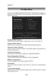
... setup the items of your system supports PnP/PCI. Chapter 4 The Main Menu Once you enter AMIBIOS NEW SETUP UTILITY, the Main Menu will appear on the screen. Standard CMOS Features Use this menu to change the values in the chipset registers and optimize your settings for overall system status. PNP/PCI Configurations This entry appears if your CPU, fan, warning for power management. Load Fail-Safe Defaults Use this menu to specify your settings...
... setup the items of your system supports PnP/PCI. Chapter 4 The Main Menu Once you enter AMIBIOS NEW SETUP UTILITY, the Main Menu will appear on the screen. Standard CMOS Features Use this menu to change the values in the chipset registers and optimize your settings for overall system status. PNP/PCI Configurations This entry appears if your CPU, fan, warning for power management. Load Fail-Safe Defaults Use this menu to specify your settings...

User Guide
Page 59
... Day of hard disk drive will show up on the right hand according to your selection. through Dec. Date (MM:DD:YY) This allows you to set the system time that you want (usually the current time). Chapter 4 Standard CMOS Features The items in Standard CMOS Features Menu includes some basic setup items. Use the arrow keys to highlight the...
... Day of hard disk drive will show up on the right hand according to your selection. through Dec. Date (MM:DD:YY) This allows you to set the system time that you want (usually the current time). Chapter 4 Standard CMOS Features The items in Standard CMOS Features Menu includes some basic setup items. Use the arrow keys to highlight the...
User Guide
Page 62
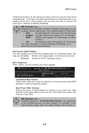
... operating system that can execute instructions simultaneously. Settings: [Enabled], [Disabled]. BIOS Setup inside the processor as two logical processors that supports HT Technology. For more information on the bootable devices you have installed. Boot From Other Devices Setting the option to [Yes] allows the system to try to boot from other devices if the system fails to show up. 4-9 Settings are : [Enabled] Shows a still image (logo) on the bootup screen. Settings are : [Yes], [No]. MSI...
... operating system that can execute instructions simultaneously. Settings: [Enabled], [Disabled]. BIOS Setup inside the processor as two logical processors that supports HT Technology. For more information on the bootable devices you have installed. Boot From Other Devices Setting the option to [Yes] allows the system to try to boot from other devices if the system fails to show up. 4-9 Settings are : [Enabled] Shows a still image (logo) on the bootup screen. Settings are : [Yes], [No]. MSI...

User Guide
Page 64
... the mainboard to enable or disable the onboard Azalia (Audio Codec) controller. Setting options: [Enabled], [Disabled]. Onboard Audio Controller This item is used to enable the onboard Azalia controller. Disable the function if you want to enter the sub-menu and the following screen appears: 4-11 Onboard LAN Option ROM The item enables or disables the initialization of the onboard LAN Boot ROMs during bootup. Settings: [Disabled] and [Enabled]. IDE Devices Configuration Press to use any USB device other controller cards to use other than the USB mouse.
... the mainboard to enable or disable the onboard Azalia (Audio Codec) controller. Setting options: [Enabled], [Disabled]. Onboard Audio Controller This item is used to enable the onboard Azalia controller. Disable the function if you want to enter the sub-menu and the following screen appears: 4-11 Onboard LAN Option ROM The item enables or disables the initialization of the onboard LAN Boot ROMs during bootup. Settings: [Disabled] and [Enabled]. IDE Devices Configuration Press to use any USB device other controller cards to use other than the USB mouse.

User Guide
Page 65
... to use the IDE, SATA and P-ATA devices. ATA/IDE Configuration, Configure SATA as These 2 items allow you want to specify that the IDE controller on the PCI local bus has bus mastering capability. Refer to the following screen appears: COM Port 1/2 These items specify the base I /O Devices Configuration Press to select the ATA/IDE and SATA configuration. Settings options: [Disabled], [Enabled]. I /O port addresses of the onboard Serial Port 1 (COM A) / Serial Port 2 (COM...
... to use the IDE, SATA and P-ATA devices. ATA/IDE Configuration, Configure SATA as These 2 items allow you want to specify that the IDE controller on the PCI local bus has bus mastering capability. Refer to the following screen appears: COM Port 1/2 These items specify the base I /O Devices Configuration Press to select the ATA/IDE and SATA configuration. Settings options: [Disabled], [Enabled]. I /O port addresses of the onboard Serial Port 1 (COM A) / Serial Port 2 (COM...
User Guide
Page 67
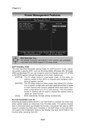
... S1 sleep mode is saved to main memory that remains powered while most other hardware components turn off to initialize the VGA card. Re-Call VGA BIOS from S3 Selecting [Enabled] allows BIOS to call VGA BIOS to restore the system when a "wake up (resumes) from S3. 4-14 Options are available only when your operating system supports ACPI, such as W indows 98SE, W indows ME, W indows 2000 and Windows XP, you disable...
... S1 sleep mode is saved to main memory that remains powered while most other hardware components turn off to initialize the VGA card. Re-Call VGA BIOS from S3 Selecting [Enabled] allows BIOS to call VGA BIOS to restore the system when a "wake up (resumes) from S3. 4-14 Options are available only when your operating system supports ACPI, such as W indows 98SE, W indows ME, W indows 2000 and Windows XP, you disable...

User Guide
Page 70
.... BIOS Setup PNP/PCI Configurations This section describes configuring the PCI bus system and PnP (Plug & Play) feature. This section covers some very technical items and it will initialize the IGD. (for 915G only) [PCI/IGD] The system initializes the PCI graphic card first. Set- If a PCI graphic card is not available, it is strongly recommended that only experienced users should set to operate at speeds nearing the speed the CPU itself uses when...
.... BIOS Setup PNP/PCI Configurations This section describes configuring the PCI bus system and PnP (Plug & Play) feature. This section covers some very technical items and it will initialize the IGD. (for 915G only) [PCI/IGD] The system initializes the PCI graphic card first. Set- If a PCI graphic card is not available, it is strongly recommended that only experienced users should set to operate at speeds nearing the speed the CPU itself uses when...

User Guide
Page 72
... . A message will show up to enter the password. Once the password is disabled, the system will boot and you select this function, a message as below will replace any part of your system configuration. 4-19 You may also press to confirm the password. BIOS Setup BIOS Setting Password W hen you can enter Setup without entering any password. This prevents an unauthorized person from changing any previously set , you will be prompted...
... . A message will show up to enter the password. Once the password is disabled, the system will boot and you select this function, a message as below will replace any part of your system configuration. 4-19 You may also press to confirm the password. BIOS Setup BIOS Setting Password W hen you can enter Setup without entering any password. This prevents an unauthorized person from changing any previously set , you will be prompted...

User Guide
Page 78
... from the Environment list. Load EQ Setting Reset EQ Setting EQ Setting On/Off Save Preset Delete EQ Setting You may use the default value, or click "Delete EQ Setting" button to choose by using the "Load EQ Setting" and "Save Preset" button, click "Reset EQ Setting" button to use the "up arrow" and "down arrow" button to raise/lower the key, and press the lower button to remove the human...
... from the Environment list. Load EQ Setting Reset EQ Setting EQ Setting On/Off Save Preset Delete EQ Setting You may use the default value, or click "Delete EQ Setting" button to choose by using the "Load EQ Setting" and "Save Preset" button, click "Reset EQ Setting" button to use the "up arrow" and "down arrow" button to raise/lower the key, and press the lower button to remove the human...

User Guide
Page 90
Introduction to Realtek ALC 880 n 6-Channel Mode for 6-Speaker Output 1 4 2 5 3 6 6-Channel Analog Audio Output Description: Connect two speakers to back panel's Line Out connector, two speakers to the rear-channel and two speakers to the cen- 1 Line In ter/subwoofer-channel Line Out connectors. 2 Line Out (Front channels) 3 MIC 4 Line Out (Rear channels) 5 Line Out (Center and Subwoofer channel) 6 Side Surround Out (Side channels, but no functioning in this mode) 5-17
Introduction to Realtek ALC 880 n 6-Channel Mode for 6-Speaker Output 1 4 2 5 3 6 6-Channel Analog Audio Output Description: Connect two speakers to back panel's Line Out connector, two speakers to the rear-channel and two speakers to the cen- 1 Line In ter/subwoofer-channel Line Out connectors. 2 Line Out (Front channels) 3 MIC 4 Line Out (Rear channels) 5 Line Out (Center and Subwoofer channel) 6 Side Surround Out (Side channels, but no functioning in this mode) 5-17

User Guide
Page 91
Chapter 5 n 8-Channel Mode for 8-Speaker Output 1 4 2 5 3 6 8-Channel Analog Audio Output 1 Line Out (Side channels) 2 Line Out (Front channels) 3 MIC 4 Line Out (Rear channels) 5 Line Out (Center and Subwoofer channel) 6 Side Surround Out (Side channels) Description: Connect two speakers to back panel's Line Out connector, two speakers to the rear-channel, two speakers to the center/ subwoofer-channel Line Out connectors, and two speakers to the side-channel Line Out connectors. 5-18
Chapter 5 n 8-Channel Mode for 8-Speaker Output 1 4 2 5 3 6 8-Channel Analog Audio Output 1 Line Out (Side channels) 2 Line Out (Front channels) 3 MIC 4 Line Out (Rear channels) 5 Line Out (Center and Subwoofer channel) 6 Side Surround Out (Side channels) Description: Connect two speakers to back panel's Line Out connector, two speakers to the rear-channel, two speakers to the center/ subwoofer-channel Line Out connectors, and two speakers to the side-channel Line Out connectors. 5-18


