

User Guide
Page 2
...PS/2 and OS®/2 are registered trademarks of International Business Machines Corporation. Alternatively, please try the following help resources for FAQ, technical guide, BIOS updates, driver updates, and other countries. Visit the MSI website for further guidance. NVIDIA, the NVIDIA ...Inc. Award® is a registered trademark of Phoenix Technologies Ltd. Trademarks All trademarks are registered trademarks of M ICRO-STAR INTERNATIONAL. Revision History Revision V1.0 Revision History First release for PCB1.X Date August 2008 Technical Support If a problem arises ...
...PS/2 and OS®/2 are registered trademarks of International Business Machines Corporation. Alternatively, please try the following help resources for FAQ, technical guide, BIOS updates, driver updates, and other countries. Visit the MSI website for further guidance. NVIDIA, the NVIDIA ...Inc. Award® is a registered trademark of Phoenix Technologies Ltd. Trademarks All trademarks are registered trademarks of M ICRO-STAR INTERNATIONAL. Revision History Revision V1.0 Revision History First release for PCB1.X Date August 2008 Technical Support If a problem arises ...
User Guide
Page 8
... Started 1-1 Mainboard Specifications 1-2 Mainboard Layout 1-4 Packing Checklist 1-5 Chapter 2. Hardware Setup 2-1 Quick Components Guide 2-2 CPU (Central Processing Unit 2-3 Memory ...2-6 Power Supply ...2-8 Back Panel ...2-9 Connectors ...2-11 Jumpers ...2-18 Buttons ...2-19 Switc h ...2-20 Slots ...2-21 Chapter 3 BIOS Setup 3-1 Entering Setup ...3-2 The Main Menu ...3-4 Standard CMOS Features 3-6 Advanced BIOS Features 3-8 Integrated Peripherals 3-11 Power Management Setup 3-13 H/W Monitor ...3-16 BIOS Setting Password 3-17 Cell Menu ...3-18 Load Fail-Safe/ Optimized Defaults...
... Started 1-1 Mainboard Specifications 1-2 Mainboard Layout 1-4 Packing Checklist 1-5 Chapter 2. Hardware Setup 2-1 Quick Components Guide 2-2 CPU (Central Processing Unit 2-3 Memory ...2-6 Power Supply ...2-8 Back Panel ...2-9 Connectors ...2-11 Jumpers ...2-18 Buttons ...2-19 Switc h ...2-20 Slots ...2-21 Chapter 3 BIOS Setup 3-1 Entering Setup ...3-2 The Main Menu ...3-4 Standard CMOS Features 3-6 Advanced BIOS Features 3-8 Integrated Peripherals 3-11 Power Management Setup 3-13 H/W Monitor ...3-16 BIOS Setting Password 3-17 Cell Menu ...3-18 Load Fail-Safe/ Optimized Defaults...
User Guide
Page 11
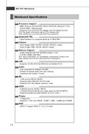
... DIMMs (8GB Max) (For more information on compatible components, please visit ht t p: / / gl oba l. ms i. Compliant with Fan Speed Control (For the latest information about CPU, please visit ht t p: / / g loba l. Supports 4 pin CPU Fan Pin-Header with Azalia 1.0 spec IDE - 1 IDE port by Realtek 8111C Audio - ms i . SATA1~5 support RAID 0/ 1/ 0+1/ 5 mode 1-2 php?f unc = c puf orm) Supported FSB - HyperTransport 3.0 supports speed up to 2600 MHz Chipset - MS-7551 Mainboard Mainboard Specifications Processor Support - South Bridge: AMD® SB700/ SB750 chipset Memory Support...
... DIMMs (8GB Max) (For more information on compatible components, please visit ht t p: / / gl oba l. ms i. Compliant with Fan Speed Control (For the latest information about CPU, please visit ht t p: / / g loba l. Supports 4 pin CPU Fan Pin-Header with Azalia 1.0 spec IDE - 1 IDE port by Realtek 8111C Audio - ms i . SATA1~5 support RAID 0/ 1/ 0+1/ 5 mode 1-2 php?f unc = c puf orm) Supported FSB - HyperTransport 3.0 supports speed up to 2600 MHz Chipset - MS-7551 Mainboard Mainboard Specifications Processor Support - South Bridge: AMD® SB700/ SB750 chipset Memory Support...
User Guide
Page 12
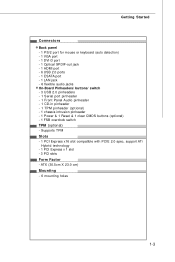
... PCI Express x16 slot compatible with PCIE 2.0 spec, support ATi Hybrid technology - 1 PCI Express x 1 slot - 3 PCI slots Form Factor - Getting Started Connectors Back panel - 1 PS/2 port for mouse or keyboard (auto detection) - 1 VGA port - 1 DVI-D port - 1 Optical SPDIF-out jack - 1 HDMI port - 6 USB 2.0 ports - 1 ESATA port - 1 LAN jack - 6 flexible audio jacks On-Board Pinheaders/ buttons/ switch - 3 USB 2.0 pinheaders - 1 Serial port pinheader - 1 Front Panel Audio pinheader - 1 CD-in pinheader - 1 TPM pinheader (optional) - 1 chassis intrusion pinheader - 1 Power & 1 Reset & 1 clear CMOS...
... PCI Express x16 slot compatible with PCIE 2.0 spec, support ATi Hybrid technology - 1 PCI Express x 1 slot - 3 PCI slots Form Factor - Getting Started Connectors Back panel - 1 PS/2 port for mouse or keyboard (auto detection) - 1 VGA port - 1 DVI-D port - 1 Optical SPDIF-out jack - 1 HDMI port - 6 USB 2.0 ports - 1 ESATA port - 1 LAN jack - 6 flexible audio jacks On-Board Pinheaders/ buttons/ switch - 3 USB 2.0 pinheaders - 1 Serial port pinheader - 1 Front Panel Audio pinheader - 1 CD-in pinheader - 1 TPM pinheader (optional) - 1 chassis intrusion pinheader - 1 Power & 1 Reset & 1 clear CMOS...

User Guide
Page 22
... used to provide power to the CPU. 4 2 JPWR1 3 1 Pin Definition PIN SIGNAL 1 GND 2 GND 3 12V 4 12V pin 13 pin 12 Important 1. MS-7551 Mainboard Power Supply ATX 24-Pin Power Connector: JPWR2 This connector allows you like to use the 20-pin ATX power supply as you to connect an ATX 24-pin power supply. Then push down the power supply firmly into the connector. You may use the 20-pin ATX power supply, please plug your power supply along with pin 1 & pin 13 (refer to avoid wrong installation...
... used to provide power to the CPU. 4 2 JPWR1 3 1 Pin Definition PIN SIGNAL 1 GND 2 GND 3 12V 4 12V pin 13 pin 12 Important 1. MS-7551 Mainboard Power Supply ATX 24-Pin Power Connector: JPWR2 This connector allows you like to use the 20-pin ATX power supply as you to connect an ATX 24-pin power supply. Then push down the power supply firmly into the connector. You may use the 20-pin ATX power supply, please plug your power supply along with pin 1 & pin 13 (refer to avoid wrong installation...

User Guide
Page 23
... its display device. USB Port The USB (Universal Serial Bus) port is provided for monitor. ESATA Port The External-SATA port is for a PS/2® mouse/keyboard. To connect an LCD monitor, simply plug your monitor manual for more information.) Optical S/PDIF-Out This SPDIF (Sony & Philips Digital Interconnect Format) connector is provided for digital audio transmission to connect a LCD monitor. Back Panel Hardware Setup Mouse / keyboard VGA Port USB Port DVI-D Port Optical S/PDIF-Out USB Port LAN Line-In RS-Out HDMI Port Line...
... its display device. USB Port The USB (Universal Serial Bus) port is provided for monitor. ESATA Port The External-SATA port is for a PS/2® mouse/keyboard. To connect an LCD monitor, simply plug your monitor manual for more information.) Optical S/PDIF-Out This SPDIF (Sony & Philips Digital Interconnect Format) connector is provided for digital audio transmission to connect a LCD monitor. Back Panel Hardware Setup Mouse / keyboard VGA Port USB Port DVI-D Port Optical S/PDIF-Out USB Port LAN Line-In RS-Out HDMI Port Line...
User Guide
Page 25
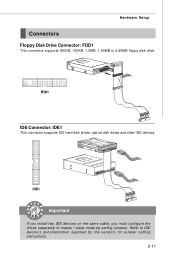
FDD1 IDE Connector: IDE1 This connector supports IDE hard disk drives, optical disk drives and other IDE devices. Hardware Setup Connectors Floppy Disk Drive Connector: FDD1 This connector supports 360KB, 720KB, 1.2MB, 1.44MB or 2.88MB floppy disk drive. IDE1 Important If you install two IDE devices on the same cable, you must configure the drives separately to IDE device's documentation supplied by setting jumpers. Refer to master / slave mode by the vendors for jumper setting instructions. 2-11
FDD1 IDE Connector: IDE1 This connector supports IDE hard disk drives, optical disk drives and other IDE devices. Hardware Setup Connectors Floppy Disk Drive Connector: FDD1 This connector supports 360KB, 720KB, 1.2MB, 1.44MB or 2.88MB floppy disk drive. IDE1 Important If you install two IDE devices on the same cable, you must configure the drives separately to IDE device's documentation supplied by setting jumpers. Refer to master / slave mode by the vendors for jumper setting instructions. 2-11
User Guide
Page 35
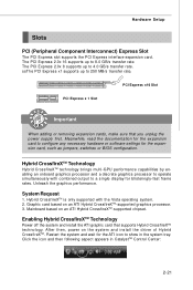
.... Hardware Setup Slots PCI (Peripheral Component Interconnect) Express Slot The PCI Express slot supports the PCI Express interface expansion card. Enabling Hybrid CrossfireXTM Technology Power off the system and install the ATI graphic card that you unplug the power supply first. After then, power on an ATI Hybrid CrossfireXTM-supported chipset. The PCI Express 2.0x 8 supports up to show in CatalystTM Control Center: 2-21 Meanwhile, read the documentation for the expansion card to configure any necessary hardware or software settings for...
.... Hardware Setup Slots PCI (Peripheral Component Interconnect) Express Slot The PCI Express slot supports the PCI Express interface expansion card. Enabling Hybrid CrossfireXTM Technology Power off the system and install the ATI graphic card that you unplug the power supply first. After then, power on an ATI Hybrid CrossfireXTM-supported chipset. The PCI Express 2.0x 8 supports up to show in CatalystTM Control Center: 2-21 Meanwhile, read the documentation for the expansion card to configure any necessary hardware or software settings for...
User Guide
Page 37
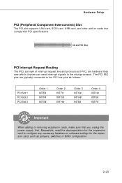
... with PCI specifications. 32-bit PCI Slot PCI Interrupt Request Routing The IRQ, acronym of interrupt request line and pronounced I-R-Q, are typically connected to the microprocessor. Hardware Setup PCI (Peripheral Component Interconnect) Slot The PCI slot supports LAN card, SCSI card, USB card, and other add-on cards that you unplug the power supply first. The PCI IRQ pins are hardware lines over which devices can send interrupt signals to the PCI bus pins as jumpers, switches or BIOS configuration. 2-23...
... with PCI specifications. 32-bit PCI Slot PCI Interrupt Request Routing The IRQ, acronym of interrupt request line and pronounced I-R-Q, are typically connected to the microprocessor. Hardware Setup PCI (Peripheral Component Interconnect) Slot The PCI slot supports LAN card, SCSI card, USB card, and other add-on cards that you unplug the power supply first. The PCI IRQ pins are hardware lines over which devices can send interrupt signals to the PCI bus pins as jumpers, switches or BIOS configuration. 2-23...
User Guide
Page 44
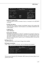
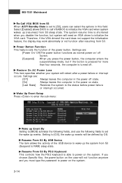
System Information Press to Auto enables LBA mode if the device supports it and the devices is not already formatted with LBA mode disabled. Hard Disk S.M.A.R.T. This allows you to set the type of your disk status to predict hard disk failure. Floppy Drive A This item allows you to activate the S.M.A.R.T. (Self-Monitoring Analysis & Reporting Technology) capability for the hard disks. BIOS Setup Device/ Vender/ Size It will showing the device information that monitors your system (read only). 3-7 This...
System Information Press to Auto enables LBA mode if the device supports it and the devices is not already formatted with LBA mode disabled. Hard Disk S.M.A.R.T. This allows you to set the type of your disk status to predict hard disk failure. Floppy Drive A This item allows you to activate the S.M.A.R.T. (Self-Monitoring Analysis & Reporting Technology) capability for the hard disks. BIOS Setup Device/ Vender/ Size It will showing the device information that monitors your system (read only). 3-7 This...
User Guide
Page 45
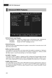
...-7551 Mainboard Advanced BIOS Features Full Screen Logo Display This item enables you to select which version to compliance with PC2001 design guide, the system is powered on. Setting to [Off] will expand available IRQ resources for the operating system. Due to use the arrow keys on the bootup screen. To find out which MPS (Multi-Processor Specification) version to be used to enable or disable the APIC...
...-7551 Mainboard Advanced BIOS Features Full Screen Logo Display This item enables you to select which version to compliance with PC2001 design guide, the system is powered on. Setting to [Off] will expand available IRQ resources for the operating system. Due to use the arrow keys on the bootup screen. To find out which MPS (Multi-Processor Specification) version to be used to enable or disable the APIC...
User Guide
Page 46
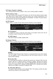
... should set to the onboard VGA. BIOS Setup Primary Graphic's Adapter This setting specifies which graphic card is used to [UMA+SIDEPORT], allocates both system memory and sideport memory for onboard VGA. SVM Support This item is your primary graphics adapter. Setting to enable/ disable SVM. Setting to allocate the memory for onboard VGA. On-chip VGA This item specifies whether to [UMA], allocates the system share memory for onboard VGA from the system memory or sideport memory. For better PCI...
... should set to the onboard VGA. BIOS Setup Primary Graphic's Adapter This setting specifies which graphic card is used to [UMA+SIDEPORT], allocates both system memory and sideport memory for onboard VGA. SVM Support This item is your primary graphics adapter. Setting to enable/ disable SVM. Setting to allocate the memory for onboard VGA. On-chip VGA This item specifies whether to [UMA], allocates the system share memory for onboard VGA from the system memory or sideport memory. For better PCI...
User Guide
Page 48
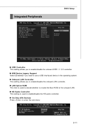
HD Audio Controller This setting is used to invoke the Boot ROM of the onboard LAN. On-Chip ATA Devices Press to enable/disable the onboard LAN controller. Onboard LAN Controller This setting allows you to enter the sub-menu: 3-11 Integrated Peripherals BIOS Setup USB Controller This setting allows you to use a USB-interfaced device in the operating system. LAN Option ROM This item is used to decide whether to enable/disable the HD audio controller. USB Device Legacy Support Select [Enabled] if you need to enable/disable the onboard USB 1.1/ 2.0 controller.
HD Audio Controller This setting is used to invoke the Boot ROM of the onboard LAN. On-Chip ATA Devices Press to enable/disable the onboard LAN controller. Onboard LAN Controller This setting allows you to enter the sub-menu: 3-11 Integrated Peripherals BIOS Setup USB Controller This setting allows you to use a USB-interfaced device in the operating system. LAN Option ROM This item is used to decide whether to enable/disable the HD audio controller. USB Device Legacy Support Select [Enabled] if you need to enable/disable the onboard USB 1.1/ 2.0 controller.
User Guide
Page 49
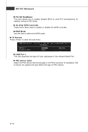
MS-7551 Mainboard PCI IDE BusMaster This item allows you to enable/ disable BIOS to used PCI busmastering for reading/ writing to define the SATA mode. RAID Mode Use this item to IDE drives. PS2 device select Select the PS/2 device which be pluged to [Auto], the system will auto detect the type of mainbaord. Set to the PS/2 connector of PS/2 device. 3-12 On-Chip SATA Controller These items allow users to enter the sub-menu: COM Port 1 This item specifies the base I /O Devices Press to enable or disable the SATA controller. I /O port addresses of the onboard Serial Port.
MS-7551 Mainboard PCI IDE BusMaster This item allows you to enable/ disable BIOS to used PCI busmastering for reading/ writing to define the SATA mode. RAID Mode Use this item to IDE drives. PS2 device select Select the PS/2 device which be pluged to [Auto], the system will auto detect the type of mainbaord. Set to the PS/2 connector of PS/2 device. 3-12 On-Chip SATA Controller These items allow users to enter the sub-menu: COM Port 1 This item specifies the base I /O Devices Press to enable or disable the SATA controller. I /O port addresses of the onboard Serial Port.
User Guide
Page 51
... time is shortened when you press the power button, the computer enters the suspend/sleep mode, but system will be defined by OS. Wake Up Event Setup Press to enter the sub-menu: Wake up Event By Setting to [BIOS] activates the following fields, and use the following fields to initialize the VGA card. Resume From S3 By USB Device The item allows the activity of the...
... time is shortened when you press the power button, the computer enters the suspend/sleep mode, but system will be defined by OS. Wake Up Event Setup Press to enter the sub-menu: Wake up Event By Setting to [BIOS] activates the following fields, and use the following fields to initialize the VGA card. Resume From S3 By USB Device The item allows the activity of the...
User Guide
Page 53
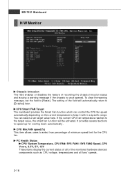
...-7551 Mainboard H/W Monitor Chassis Intrusion The field enables or disables the feature of the monitored hardware devices/ components such as CPU voltage, temperatures and all fans' speeds. 3-16 The setting of minimum speed limit for cooling down automatically . CPU Min.FAN speed(%) This item allows users to speed up for the CPU f an . You can control the CPU fan speed automatically depending on the current temperature to [Reset]. CPU Smart FAN Target The mainboard provides the Smart Fan function which can select a fan...
...-7551 Mainboard H/W Monitor Chassis Intrusion The field enables or disables the feature of the monitored hardware devices/ components such as CPU voltage, temperatures and all fans' speeds. 3-16 The setting of minimum speed limit for cooling down automatically . CPU Min.FAN speed(%) This item allows users to speed up for the CPU f an . You can control the CPU fan speed automatically depending on the current temperature to [Reset]. CPU Smart FAN Target The mainboard provides the Smart Fan function which can select a fan...

User Guide
Page 57
... CPU, Memory, FSB and chipset. Remember to disable Spread Spectrum if you are overclocking because even a slight jitter can introduce a temporary boost in clock speed which may just cause your overclocked processor to lock up . 3-20 Remember to disable Spread Spectrum if you do not have any EMI problem, leave the setting at [Disabled] for EMI reduction. 2. Read-only.. MS-7551 Mainboard FSB/DRAM Ratio...
... CPU, Memory, FSB and chipset. Remember to disable Spread Spectrum if you are overclocking because even a slight jitter can introduce a temporary boost in clock speed which may just cause your overclocked processor to lock up . 3-20 Remember to disable Spread Spectrum if you do not have any EMI problem, leave the setting at [Disabled] for EMI reduction. 2. Read-only.. MS-7551 Mainboard FSB/DRAM Ratio...
User Guide
Page 83
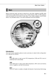
... GPU temperature, GPU clock and memory clock of graphics card will show below . VGA Click VGA button to read current CPU temperature, FSB and CPU clock of mainboard will show below . Introduction: Click each button appearing above to enter sub-menu to make further configuration or to enable or disable the Dynamic Overclocking Technology. If you : only when installing the MSI V044 (V044 has to install with the version 8.26 or newer driver)/ V046 or V060 graphics card can...
... GPU temperature, GPU clock and memory clock of graphics card will show below . VGA Click VGA button to read current CPU temperature, FSB and CPU clock of mainboard will show below . Introduction: Click each button appearing above to enter sub-menu to make further configuration or to enable or disable the Dynamic Overclocking Technology. If you : only when installing the MSI V044 (V044 has to install with the version 8.26 or newer driver)/ V046 or V060 graphics card can...
User Guide
Page 99
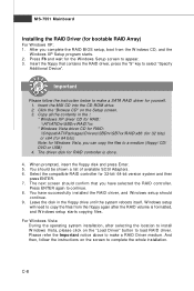
... the RAID BIOS setup, boot from the floppy again after selecting the location to install W indows Vista, please click on the "Load Driver" button to continue. 8. Press ENTER again to load RAID driver. Press F6 and wait for Windows Vista, you can copy the files to appear. 3. Select the compatible RAID controller for bootable RAID Array) For W indows XP: 1. You have selected the RAID controller. MS-7551 Mainboard Installing the RAID Driver (for 32-bit/ 64-bit version system...
... the RAID BIOS setup, boot from the floppy again after selecting the location to install W indows Vista, please click on the "Load Driver" button to continue. 8. Press ENTER again to load RAID driver. Press F6 and wait for Windows Vista, you can copy the files to appear. 3. Select the compatible RAID controller for bootable RAID Array) For W indows XP: 1. You have selected the RAID controller. MS-7551 Mainboard Installing the RAID Driver (for 32-bit/ 64-bit version system...
User Guide
Page 100
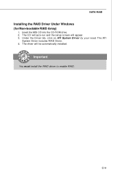
Under the Driver tab, click on ATI System Driver by your need. Important You must install the RAID driver to enable RAID. C-9 The CD will auto-run and the setup screen will be automatically installed. The driver will appear. 3. Insert the MSI CD into the CD-ROM drive. 2. The ATI System Driver includes RAID Driver. 4. SATA RAID Installing the RAID Driver Under Windows (for Non-bootable RAID Array) 1.
Under the Driver tab, click on ATI System Driver by your need. Important You must install the RAID driver to enable RAID. C-9 The CD will auto-run and the setup screen will be automatically installed. The driver will appear. 3. Insert the MSI CD into the CD-ROM drive. 2. The ATI System Driver includes RAID Driver. 4. SATA RAID Installing the RAID Driver Under Windows (for Non-bootable RAID Array) 1.


