
User Guide
Page 1
... harmful interference to operate the equipment. Operation is subject to part 15 of the FCC Rules. VOIR LA NOTICE D'NSTALLATION AVANT DE RACCORDER AU RESEAU. Micro-Star International MS-7061 This device complies with Part 15 of the FCC rules. Notice 2 Shielded interface cables and A.C. FCC-B Radio Frequency Interference Statement This...
... harmful interference to operate the equipment. Operation is subject to part 15 of the FCC Rules. VOIR LA NOTICE D'NSTALLATION AVANT DE RACCORDER AU RESEAU. Micro-Star International MS-7061 This device complies with Part 15 of the FCC rules. Notice 2 Shielded interface cables and A.C. FCC-B Radio Frequency Interference Statement This...

User Guide
Page 2
... a registered trademark of their respective owners. NVIDIA, the NVIDIA logo, DualNet, and nForce are the properties of Novell, Inc. Award® is a registered trademark of MICRO-STAR INTERNATIONAL. We take every care in the United States and/or other countries. AMI® is a registered trademark of Multi-language version for PCB...
... a registered trademark of their respective owners. NVIDIA, the NVIDIA logo, DualNet, and nForce are the properties of Novell, Inc. Award® is a registered trademark of MICRO-STAR INTERNATIONAL. We take every care in the United States and/or other countries. AMI® is a registered trademark of Multi-language version for PCB...

User Guide
Page 3
Do not cover the openings. 6. Always Unplug the Power Cord before inserting any liquid into the equipment. - If any of explosion if battery is damaged. - Liquid has penetrated into the opening that people can not get the equipment checked by the manufacturer. The equipment has dropped and damaged. - Replace only with the same or equivalent type recommended by a service personnel: - iii The openings on the enclosure are for future reference. 3. Make sure the voltage of breakage. 12. Place the power cord such a way that could damage or cause electrical shock. 11. Do not ...
Do not cover the openings. 6. Always Unplug the Power Cord before inserting any liquid into the equipment. - If any of explosion if battery is damaged. - Liquid has penetrated into the opening that people can not get the equipment checked by the manufacturer. The equipment has dropped and damaged. - Replace only with the same or equivalent type recommended by a service personnel: - iii The openings on the enclosure are for future reference. 3. Make sure the voltage of breakage. 12. Place the power cord such a way that could damage or cause electrical shock. 11. Do not ...

User Guide
Page 5
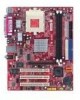
... 1 Designed to fit the advanced AMD ® AthlonTM/AthlonTM XP/DuronTM processors in 462 pin package, the KM4M-V/KM4AM-V/KM3M-V Series delivers a high performance and professional desktop platform solution. Layout Top : mouse Bottom: keyboard SOCKET 462 ...FANCPU1 CONN 1 FDD 1 Top : Parallel Port Bottom: COM A VGA port FANSYS1 ATX Power Supply DIMM 2 DIMM 1 USB ports JPW1 Top: LAN Jack Bottom: USB ports VIA VT6103 Line-In...system efficiency. Introduction Thank you for choosing the KM4M-V/KM4AM-V/KM3M-V Series (MS-7061 v1.X) micro ATX mainboard.
... 1 Designed to fit the advanced AMD ® AthlonTM/AthlonTM XP/DuronTM processors in 462 pin package, the KM4M-V/KM4AM-V/KM3M-V Series delivers a high performance and professional desktop platform solution. Layout Top : mouse Bottom: keyboard SOCKET 462 ...FANCPU1 CONN 1 FDD 1 Top : Parallel Port Bottom: COM A VGA port FANSYS1 ATX Power Supply DIMM 2 DIMM 1 USB ports JPW1 Top: LAN Jack Bottom: USB ports VIA VT6103 Line-In...system efficiency. Introduction Thank you for choosing the KM4M-V/KM4AM-V/KM3M-V Series (MS-7061 v1.X) micro ATX mainboard.

User Guide
Page 6
... 8X (for KM400A only). - Can connect up to 3000+ or above @ 266/333 MHz. (For the latest information about CPU, please visit http://www.msi.com.tw/program/products/mainboard/mbd/pro_mbd_cpu_support.php ) Chipset ! FSB @ 266/333/400 MHz. (for KM400 & KM400A) slot. ! On-Board IDE ! ...for KM266 Pro & KM400 ); FSB @ 266/333 MHz. (for single channel mode. (For the updated supporting memory modules, please visit http://www.msi.com.tw/program/products/mainboard/mbd/pro_mbd_trp_list.php ) Slots ! Integrated Direct Sound AC97 audio. - Dual channel Ultra DMA 33/66/100/133 master ...
... 8X (for KM400A only). - Can connect up to 3000+ or above @ 266/333 MHz. (For the latest information about CPU, please visit http://www.msi.com.tw/program/products/mainboard/mbd/pro_mbd_cpu_support.php ) Chipset ! FSB @ 266/333/400 MHz. (for KM400 & KM400A) slot. ! On-Board IDE ! ...for KM266 Pro & KM400 ); FSB @ 266/333 MHz. (for single channel mode. (For the updated supporting memory modules, please visit http://www.msi.com.tw/program/products/mainboard/mbd/pro_mbd_trp_list.php ) Slots ! Integrated Direct Sound AC97 audio. - Dual channel Ultra DMA 33/66/100/133 master ...

User Guide
Page 7
VIA VT8237 integrated MAC + VIA 6103 PHY. - 1 RJ45 LAN Jack. Micro-ATX Form Factor: 245 mm x 192mm. Dimension ! VRAM size maximum is to 64MB. (Optional). ! VIA1617A codec. - 5.1 channel AC'97 software Audio. The mainboard provides a Desktop Management ...
VIA VT8237 integrated MAC + VIA 6103 PHY. - 1 RJ45 LAN Jack. Micro-ATX Form Factor: 245 mm x 192mm. Dimension ! VRAM size maximum is to 64MB. (Optional). ! VIA1617A codec. - 5.1 channel AC'97 software Audio. The mainboard provides a Desktop Management ...

User Guide
Page 8
... on connecting the peripheral devices, such as how to setup the jumpers on the computer. (For the latest information about CPU, please visit http://www.msi.com.tw/program/products/mainboard/mbd/pro_mbd_cpu_support.php ) Example of CPU Core Speed Derivation Procedure If CPU Clock = 100MHz Core/Bus ratio = 14 then CPU...
... on connecting the peripheral devices, such as how to setup the jumpers on the computer. (For the latest information about CPU, please visit http://www.msi.com.tw/program/products/mainboard/mbd/pro_mbd_cpu_support.php ) Example of CPU Core Speed Derivation Procedure If CPU Clock = 100MHz Core/Bus ratio = 14 then CPU...

User Guide
Page 9
Please turn off the power and unplug the power cord before installing the CPU. 2. If the CPU is properly and completely embedded into the socket. Use one end of the clip to hook the latch of the correct installation procedures may need a screw drive to press down firmly into the socket and can only fit in the correct orientation. 4. Look for Socket 462 1. Press the CPU down the other latch to your mainboard. 5. Pull the lever sideways away from the socket. You may cause permanent damages to fix the cooling fan set. Please consult your fingers pressing ...
Please turn off the power and unplug the power cord before installing the CPU. 2. If the CPU is properly and completely embedded into the socket. Use one end of the clip to hook the latch of the correct installation procedures may need a screw drive to press down firmly into the socket and can only fit in the correct orientation. 4. Look for Socket 462 1. Press the CPU down the other latch to your mainboard. 5. Pull the lever sideways away from the socket. You may cause permanent damages to fix the cooling fan set. Please consult your fingers pressing ...

User Guide
Page 10
...Overheating... Installing DDR Modules 1. Insert the DIMM memory module vertically into the DIMM slot. While replacing the CPU, always turn off the ATX power supply or unplug the power supply's power cord from overheating. Memory modules can be installed. (For the updated supporting memory modules,... please visit http://www.msi.com.tw/program/products/mainboard/mbd/pro_mbd_trp_list.php ) Install at each side of the DIMM slot will seriously damage the CPU and...
...Overheating... Installing DDR Modules 1. Insert the DIMM memory module vertically into the DIMM slot. While replacing the CPU, always turn off the ATX power supply or unplug the power supply's power cord from overheating. Memory modules can be installed. (For the updated supporting memory modules,... please visit http://www.msi.com.tw/program/products/mainboard/mbd/pro_mbd_trp_list.php ) Install at each side of the DIMM slot will seriously damage the CPU and...

User Guide
Page 11
...that all components are aligned. -5V 5V Then push down the power supply firmly into the connector. 5V ATX 12V Power Connector: JPW1 GND This 12V power connector is suggested. 3.3V ATX 20-Pin Power Connector: CONN1 -12V GND This connector allows you must enter the BIOS setting and clear ...the status. To PS_ON GND connect to the ATX power supply, make sure that no damage will record this status. To clear the warning, you to connect to 2-pin connector chassis switch. ...
...that all components are aligned. -5V 5V Then push down the power supply firmly into the connector. 5V ATX 12V Power Connector: JPW1 GND This 12V power connector is suggested. 3.3V ATX 20-Pin Power Connector: CONN1 -12V GND This connector allows you must enter the BIOS setting and clear ...the status. To PS_ON GND connect to the ATX power supply, make sure that no damage will record this status. To clear the warning, you to connect to 2-pin connector chassis switch. ...

User Guide
Page 12
.../133 controller that provides PIO mode 0~4, Bus Master, and Ultra DMA 33/66/100/133 function. The first hard drive should be connected to IDE1. MSI Reminds You... Always consult the vendors for jumper setting instructions. 8 If the mainboard has a System Hardware Monitor chipset on cable, you must configure the second... jumper accordingly. You can connect up to four hard disk drives, CD-ROM, 120MB Floppy and other devices. take advantage of the CPU fan control. MSI Reminds You... 1.
.../133 controller that provides PIO mode 0~4, Bus Master, and Ultra DMA 33/66/100/133 function. The first hard drive should be connected to IDE1. MSI Reminds You... Always consult the vendors for jumper setting instructions. 8 If the mainboard has a System Hardware Monitor chipset on cable, you must configure the second... jumper accordingly. You can connect up to four hard disk drives, CD-ROM, 120MB Floppy and other devices. take advantage of the CPU fan control. MSI Reminds You... 1.

User Guide
Page 13
... the rear audio ports. JFP1 is compliant with Intel Front Panel I /O Connectivity Design Guide. AUD_MIC_BIAS AUD_FPOUT_R AUD_MIC HP_ON AUD_FPOUT_L 9 1 10 2 AUD_SPEAKER_L KEY AUD_SPEAKER_R AUD_GND AUD_VCC MSI Reminds You... JUSB2 Serial Port Connector: COM2 1 2 The main board offers one serial port COM2. USB0- VCC USB1+ GND USBOC 2 10 1 9 VCC KEY GND USB0...
... the rear audio ports. JFP1 is compliant with Intel Front Panel I /O Connectivity Design Guide. AUD_MIC_BIAS AUD_FPOUT_R AUD_MIC HP_ON AUD_FPOUT_L 9 1 10 2 AUD_SPEAKER_L KEY AUD_SPEAKER_R AUD_GND AUD_VCC MSI Reminds You... JUSB2 Serial Port Connector: COM2 1 2 The main board offers one serial port COM2. USB0- VCC USB1+ GND USBOC 2 10 1 9 VCC KEY GND USB0...

User Guide
Page 14
PIN SIGNAL 1 DCD 2 SIN 3 SOUT 4 DTR 5 GND DESCRIPTION PIN Data Carry Detect 6 Serial In or 7 Receive Data 8 Serial Out or 9 Transmit Data SIGNAL DSR RTS CTS RI DESCRIPTION Data Set Ready Request To Send Clear To Send Ring Indicate Serial ATA HDD Connectors: SATA1/SATA2 (for KM400A only) SW1 3 1 3 1 3 1 SW2 3 1 3 1 3 1 Clear CMOS Jumper: JBAT1 There is a CMOS RAM on board that has a power supply from external battery to keep the data of 150 MB/s and are fully compliant with Serial ATA 1.0 specifications. Each Serial ATA connector can connect to adjust the jumpers....
PIN SIGNAL 1 DCD 2 SIN 3 SOUT 4 DTR 5 GND DESCRIPTION PIN Data Carry Detect 6 Serial In or 7 Receive Data 8 Serial Out or 9 Transmit Data SIGNAL DSR RTS CTS RI DESCRIPTION Data Set Ready Request To Send Clear To Send Ring Indicate Serial ATA HDD Connectors: SATA1/SATA2 (for KM400A only) SW1 3 1 3 1 3 1 SW2 3 1 3 1 3 1 Clear CMOS Jumper: JBAT1 There is a CMOS RAM on board that has a power supply from external battery to keep the data of 150 MB/s and are fully compliant with Serial ATA 1.0 specifications. Each Serial ATA connector can connect to adjust the jumpers....

User Guide
Page 15
... instructions 1 1 1 below to 1-2 pin position. PCI Interrupt Request Routing The IRQ, abbreviation of 3D graphics. Then return to clear the data: Keep Data Clear Data MSI Reminds You... AGP is on . The mainboard supports 4X (for KM266Pro)/8X (for the expansion card, such as follows: PCI Slot 1 PCI Slot 2 PCI Slot...
... instructions 1 1 1 below to 1-2 pin position. PCI Interrupt Request Routing The IRQ, abbreviation of 3D graphics. Then return to clear the data: Keep Data Clear Data MSI Reminds You... AGP is on . The mainboard supports 4X (for KM266Pro)/8X (for the expansion card, such as follows: PCI Slot 1 PCI Slot 2 PCI Slot...

User Guide
Page 16
You may also restart the system by turning it OFF and On or pressing the RESET button. Advanced Chipset Features Use this menu to specify your settings for frequency/voltage control. PC Health Status This entry shows your system performance. PNP/PCI Configurations This entry appears if your settings for integrated peripherals. Load Fail-Safe Defaults 12 Integrated Peripherals Use this menu to change the values in the chipset registers and optimize your PC health status. Power Management Setup Use this menu to enter Setup. Frequency/Voltage Control Use this ...
You may also restart the system by turning it OFF and On or pressing the RESET button. Advanced Chipset Features Use this menu to specify your settings for frequency/voltage control. PC Health Status This entry shows your system performance. PNP/PCI Configurations This entry appears if your settings for integrated peripherals. Load Fail-Safe Defaults 12 Integrated Peripherals Use this menu to change the values in the chipset registers and optimize your PC health status. Power Management Setup Use this menu to enter Setup. Frequency/Voltage Control Use this ...

User Guide
Page 17
Save & Exit Setup Save changes to load the BIOS values for stable system performance operations. Use this menu to CMOS and exit setup. Set Supervisor Password Use this menu to set Supervisor Password. Set User Password Use this menu to load factory default settings into the BIOS for the best system performance, but the system stability may be affected. Exit Without Saving Abandon all changes and exit setup. 13 Load Optimized Defaults Use this menu to set User Password.
Save & Exit Setup Save changes to load the BIOS values for stable system performance operations. Use this menu to CMOS and exit setup. Set Supervisor Password Use this menu to set Supervisor Password. Set User Password Use this menu to load factory default settings into the BIOS for the best system performance, but the system stability may be affected. Exit Without Saving Abandon all changes and exit setup. 13 Load Optimized Defaults Use this menu to set User Password.

User Guide
Page 18
...Remember to [Enabled] for optimal system stability and performance. If you do not have any EMI problem, leave the setting at http://www.msi.com.tw. 14 When set to disable Spread Spectrum if you are overclocking because even a slight jitter can introduce a temporary boost in ...clock speed which may just cause your overclocked processor to flatter curves. Spread Spectrum When the motherboard's clock generator pulses, the extreme values (spikes) of the pulses are reduced to lock up. But if you are plagued by modulating the ...
...Remember to [Enabled] for optimal system stability and performance. If you do not have any EMI problem, leave the setting at http://www.msi.com.tw. 14 When set to disable Spread Spectrum if you are overclocking because even a slight jitter can introduce a temporary boost in ...clock speed which may just cause your overclocked processor to flatter curves. Spread Spectrum When the motherboard's clock generator pulses, the extreme values (spikes) of the pulses are reduced to lock up. But if you are plagued by modulating the ...

User Guide
Page 51
VIA VT8237 集成于 MAC + VIA 6103 PHY - 1 个 RJ45 LAN 插孔 BIOS BIOS 提供"Plug & Play DMI Micro-ATX 245 mm x 192mm 6 PS2 VRAM 64MB CPU 47 VIA1617A 5.1 声道 AC'97 LAN - - 1 SPP/EPP/ECP 模式 - 2 个 SATA KM400 & KM400A) - 8 个 USB 2.0 4/ 前置* 4) - 3 Line-In/Line-Out/Mic Intel COM2 音频 -
VIA VT8237 集成于 MAC + VIA 6103 PHY - 1 个 RJ45 LAN 插孔 BIOS BIOS 提供"Plug & Play DMI Micro-ATX 245 mm x 192mm 6 PS2 VRAM 64MB CPU 47 VIA1617A 5.1 声道 AC'97 LAN - - 1 SPP/EPP/ECP 模式 - 2 个 SATA KM400 & KM400A) - 8 个 USB 2.0 4/ 前置* 4) - 3 Line-In/Line-Out/Mic Intel COM2 音频 -

User Guide
Page 55
电源供应 ATX 300 瓦 11 1 3.3V -12V 3.3V 3.3V GND GND PS_ON 5V ATX 20-Pin CONN1 GND GND GND 5V ATX ATX GND GND -5V PW_OK 5V 5V_SB 5V 12V 20 10 ATX 12V JPW1 12 GND GND 此 12V CPU 供电。 12V 12V 34 FDD1 FDD,支持 360K、720K、1.2M、1.44M 和 2.88M JCI1(选配) GND 2 CINTRU 1 2-pin BIOS 设定程 R CD-In 接口:JCD1 CD-ROM GND L 51
电源供应 ATX 300 瓦 11 1 3.3V -12V 3.3V 3.3V GND GND PS_ON 5V ATX 20-Pin CONN1 GND GND GND 5V ATX ATX GND GND -5V PW_OK 5V 5V_SB 5V 12V 20 10 ATX 12V JPW1 12 GND GND 此 12V CPU 供电。 12V 12V 34 FDD1 FDD,支持 360K、720K、1.2M、1.44M 和 2.88M JCI1(选配) GND 2 CINTRU 1 2-pin BIOS 设定程 R CD-In 接口:JCD1 CD-ROM GND L 51

User Guide
Page 57
JUSB2 53 JFP1/JFP2 2 JFP1 和 JFP2。JFP1 是符合 Intel® I/O Power Power LED Switch 2 10 1 9 Speaker 2 8 1 7 HDD Reset LED Switch JFP1 Power LED JFP2 JAUD1 JAUD1 JAUD1 是符合 Intel® I/O AUD_MIC_BIAS AUD_FPOUT_R AUD_MIC HP_ON AUD_FPOUT_L 9 1 10 2 AUD_SPEAKER_L KEY AUD_SPEAKER_R AUD_GND AUD_VCC 5 & 6, 9 & 10 9 1 Line-Out 10 2 前置 USB 接口:JUSB1/JUSB2 2 个 USB2.0 的接口 JUSB1/JUSB2 Intel® I/O USB 2.0 480Mbps,是 ...
JUSB2 53 JFP1/JFP2 2 JFP1 和 JFP2。JFP1 是符合 Intel® I/O Power Power LED Switch 2 10 1 9 Speaker 2 8 1 7 HDD Reset LED Switch JFP1 Power LED JFP2 JAUD1 JAUD1 JAUD1 是符合 Intel® I/O AUD_MIC_BIAS AUD_FPOUT_R AUD_MIC HP_ON AUD_FPOUT_L 9 1 10 2 AUD_SPEAKER_L KEY AUD_SPEAKER_R AUD_GND AUD_VCC 5 & 6, 9 & 10 9 1 Line-Out 10 2 前置 USB 接口:JUSB1/JUSB2 2 个 USB2.0 的接口 JUSB1/JUSB2 Intel® I/O USB 2.0 480Mbps,是 ...