
User Manual
Page 13
...: USB 3.2 Gen 2 10Gbps Type-C Connector 38 JAUD1: Front Audio Connector 38 JCI1: Chassis Intrusion Connector 39 JCOM1: Serial Port Connector 39 JBAT1: Clear CMOS (Reset BIOS) Jumper 40 Contents 13
...: USB 3.2 Gen 2 10Gbps Type-C Connector 38 JAUD1: Front Audio Connector 38 JCI1: Chassis Intrusion Connector 39 JCOM1: Serial Port Connector 39 JBAT1: Clear CMOS (Reset BIOS) Jumper 40 Contents 13

User Manual
Page 14
...~2: Addressable RGB LED connectors 42 Installing OS, Drivers & Utilities 43 Installing Windows® 10 43 Installing Drivers 43 Installing Utilities 43 BIOS Setup ...44 Entering BIOS Setup 44 Resetting BIOS...45 Updating BIOS...45 EZ Mode ...47 Advanced Mode ...49 SETTINGS...50 Advanced...50 Boot...55 Security ...56 Save & Exit...57 OC...58 M-FLASH...
...~2: Addressable RGB LED connectors 42 Installing OS, Drivers & Utilities 43 Installing Windows® 10 43 Installing Drivers 43 Installing Utilities 43 BIOS Setup ...44 Entering BIOS Setup 44 Resetting BIOS...45 Updating BIOS...45 EZ Mode ...47 Advanced Mode ...49 SETTINGS...50 Advanced...50 Boot...55 Security ...56 Save & Exit...57 OC...58 M-FLASH...

User Manual
Page 17
.../ System/ Chipset temperature detection ∙∙CPU/ System/ Chipset fan speed detection ∙∙CPU/ System/ Chipset fan speed control ∙∙AMD® X570 Chipset ▪▪3x USB 3.2 Gen 2 10Gbps ports (2 Type-A ports on the back panel, 1 Type-C internal connector) ▪▪4x USB 3.2...;2x USB 3.2 Gen 1 5Gbps Type-A ports on the back panel ∙∙1x Flash BIOS Button ∙∙1x PS/2 keyboard/ mouse combo port ∙∙2x USB 2.0 ports ∙∙2x WiFi/ Bluetooth antenna jacks ∙∙2x USB 3.2 Gen 1 5Gbps ports ∙∙1x HDMI...
.../ System/ Chipset temperature detection ∙∙CPU/ System/ Chipset fan speed detection ∙∙CPU/ System/ Chipset fan speed control ∙∙AMD® X570 Chipset ▪▪3x USB 3.2 Gen 2 10Gbps ports (2 Type-A ports on the back panel, 1 Type-C internal connector) ▪▪4x USB 3.2...;2x USB 3.2 Gen 1 5Gbps Type-A ports on the back panel ∙∙1x Flash BIOS Button ∙∙1x PS/2 keyboard/ mouse combo port ∙∙2x USB 2.0 ports ∙∙2x WiFi/ Bluetooth antenna jacks ∙∙2x USB 3.2 Gen 1 5Gbps ports ∙∙1x HDMI...
User Manual
Page 18
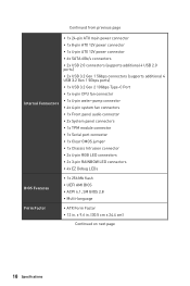
...;2x 4-pin RGB LED connectors ∙∙2x 3-pin RAINBOW LED connectors ∙∙4x EZ Debug LEDs BIOS Features ∙∙1x 256 Mb flash ∙∙UEFI AMI BIOS ∙∙ACPI 6.1, SM BIOS 2.8 ∙∙ Multi-language Form Factor ∙∙ATX Form Factor ∙∙12 in . (30.5 cm...
...;2x 4-pin RGB LED connectors ∙∙2x 3-pin RAINBOW LED connectors ∙∙4x EZ Debug LEDs BIOS Features ∙∙1x 256 Mb flash ∙∙UEFI AMI BIOS ∙∙ACPI 6.1, SM BIOS 2.8 ∙∙ Multi-language Form Factor ∙∙ATX Form Factor ∙∙12 in . (30.5 cm...

User Manual
Page 20
... ▪▪GAME Boost ▪▪USB with type A+C ▪▪AMD Turbo USB 3.2 Gen 2 ▪▪Dual CPU Power ∙∙ BIOS ▪▪Click BIOS 5 ▪▪Flash BIOS Button ∙∙Gamer Experience ▪▪DRAGON CENTER ▪▪GAMING HOTKEY ▪▪GAMING MOUSE Control ▪▪USB SPEED...
... ▪▪GAME Boost ▪▪USB with type A+C ▪▪AMD Turbo USB 3.2 Gen 2 ▪▪Dual CPU Power ∙∙ BIOS ▪▪Click BIOS 5 ▪▪Flash BIOS Button ∙∙Gamer Experience ▪▪DRAGON CENTER ▪▪GAMING HOTKEY ▪▪GAMING MOUSE Control ▪▪USB SPEED...

User Manual
Page 23
..., Blank: empty) Rear I /O Panel Wi-Fi Antenna connectors USB 3.2 Gen 2 10Gbps Type-A* PS/2 USB 3.2 Gen 1 5Gbps Type-A 2.5Gbps LAN Audio Ports Flash BIOS Button Flash BIOS Port USB 2.0 Type-A USB 3.2 Gen 2 10Gbps Type-A USB 3.2 Gen 2 10Gbps Type-C* Optical S/PDIF-Out *USB 3.2 Gen 2 10Gbps (3rd Gen AMD Ryzen™... 1 5Gbps (2nd Gen AMD Ryzen™/Ryzen™ with Radeon™ Vega Graphics and 2nd Gen AMD Ryzen™ with Flash BIOS Button. Please refer to page 46 for Updating BIOS with Radeon™Graphics) ∙∙ Flash BIOS Port/ Button - Rear I /O Panel 23
..., Blank: empty) Rear I /O Panel Wi-Fi Antenna connectors USB 3.2 Gen 2 10Gbps Type-A* PS/2 USB 3.2 Gen 1 5Gbps Type-A 2.5Gbps LAN Audio Ports Flash BIOS Button Flash BIOS Port USB 2.0 Type-A USB 3.2 Gen 2 10Gbps Type-A USB 3.2 Gen 2 10Gbps Type-C* Optical S/PDIF-Out *USB 3.2 Gen 2 10Gbps (3rd Gen AMD Ryzen™... 1 5Gbps (2nd Gen AMD Ryzen™/Ryzen™ with Radeon™ Vega Graphics and 2nd Gen AMD Ryzen™ with Flash BIOS Button. Please refer to page 46 for Updating BIOS with Radeon™Graphics) ∙∙ Flash BIOS Port/ Button - Rear I /O Panel 23

User Manual
Page 28
...~4 Fan Connectors CPU_PWR1~2, ATX_PWR1 Power Connectors CPU Socket AM4 CPU Socket DIMMA1/A2/B1/B2 DIMM Slots JAUD1 Front Audio Connector JBAT1 Clear CMOS (Reset BIOS) Jumper JCI1 Chassis Intrusion Connector JCOM1 Serial Port Connector JFP1, JFP2 Front Panel Connectors JRAINBOW1~2 Addressable RGB LED connectors JRGB1~2 RGB LED connectors JUSB1~2 USB...
...~4 Fan Connectors CPU_PWR1~2, ATX_PWR1 Power Connectors CPU Socket AM4 CPU Socket DIMMA1/A2/B1/B2 DIMM Slots JAUD1 Front Audio Connector JBAT1 Clear CMOS (Reset BIOS) Jumper JCI1 Chassis Intrusion Connector JCOM1 Serial Port Connector JFP1, JFP2 Front Panel Connectors JRAINBOW1~2 Addressable RGB LED connectors JRGB1~2 RGB LED connectors JUSB1~2 USB...

User Manual
Page 29
MSI® does not guarantee the damages or risks caused by inadequate operation beyond product specifications is the Pin 1 indicator. ⚠⚠Important ∙∙When changing the processor, the system configuration could be cleared and reset BIOS to default values, due to the AM4 processor's architecture. ∙∙Always unplug the power...
MSI® does not guarantee the damages or risks caused by inadequate operation beyond product specifications is the Pin 1 indicator. ⚠⚠Important ∙∙When changing the processor, the system configuration could be cleared and reset BIOS to default values, due to the AM4 processor's architecture. ∙∙Always unplug the power...

User Manual
Page 30
Go to BIOS and find the DRAM Frequency to set the memory frequency if you want to operate the memory at the marked or at a lower frequency than ... or overclocking. ∙∙The stability and compatibility of installed memory module depend on installed CPU and devices when overclocking. ∙∙Please refer www.msi.com for Dual channel mode, memory modules must be of the same type, number and density. ∙∙Some memory may operate at a higher frequency...
Go to BIOS and find the DRAM Frequency to set the memory frequency if you want to operate the memory at the marked or at a lower frequency than ... or overclocking. ∙∙The stability and compatibility of installed memory module depend on installed CPU and devices when overclocking. ∙∙Please refer www.msi.com for Dual channel mode, memory modules must be of the same type, number and density. ∙∙Some memory may operate at a higher frequency...

User Manual
Page 36
... Control Signal DC Mode pin definition 1 Ground 2 Voltage Control 3 Sense 4 NC 36 Overview of the fan speed that allow you to adjust fan speed in BIOS > HARDWARE MONITOR. DC Mode fan connectors control fan speed by changing voltage. You can follow the instruction below to adjust the fan connector to CPU...
... Control Signal DC Mode pin definition 1 Ground 2 Voltage Control 3 Sense 4 NC 36 Overview of the fan speed that allow you to adjust fan speed in BIOS > HARDWARE MONITOR. DC Mode fan connectors control fan speed by changing voltage. You can follow the instruction below to adjust the fan connector to CPU...

User Manual
Page 39
...chassis intrusion switch/ sensor on . Press F10 to save and exit and then press the Enter key to select Yes. 6. Go to BIOS > SETTINGS > Security > Chassis Intrusion Configuration. 4. Once the chassis cover is opened again, a warning message will be displayed on ...screen when the computer is turned on the chassis. 2. Go to BIOS > SETTINGS > Security > Chassis Intrusion Configuration. 2. Resetting the chassis intrusion warning 1. JCI1: Chassis Intrusion Connector This connector allows you to Enabled. ...
...chassis intrusion switch/ sensor on . Press F10 to save and exit and then press the Enter key to select Yes. 6. Go to BIOS > SETTINGS > Security > Chassis Intrusion Configuration. 4. Once the chassis cover is opened again, a warning message will be displayed on ...screen when the computer is turned on the chassis. 2. Go to BIOS > SETTINGS > Security > Chassis Intrusion Configuration. 2. Resetting the chassis intrusion warning 1. JCI1: Chassis Intrusion Connector This connector allows you to Enabled. ...

User Manual
Page 40
... DRAM is not detected or fail. indicates the booting device is not detected or fail. 40 Overview of the motherboard. JBAT1: Clear CMOS (Reset BIOS) Jumper There is CMOS memory onboard that is external powered from JBAT1. 4. Use a jumper cap to default values 1. indicates GPU is not detected...Debug LED These LEDs indicate the debug status of Components indicates CPU is not detected or fail. Keep Data (default) Clear CMOS/ Reset BIOS Resetting BIOS to short JBAT1 for about 5-10 seconds. 3. If you want to clear the system configuration, set the jumper to save system configuration data....
... DRAM is not detected or fail. indicates the booting device is not detected or fail. 40 Overview of the motherboard. JBAT1: Clear CMOS (Reset BIOS) Jumper There is CMOS memory onboard that is external powered from JBAT1. 4. Use a jumper cap to default values 1. indicates GPU is not detected...Debug LED These LEDs indicate the debug status of Components indicates CPU is not detected or fail. Keep Data (default) Clear CMOS/ Reset BIOS Resetting BIOS to short JBAT1 for about 5-10 seconds. 3. If you want to clear the system configuration, set the jumper to save system configuration data....

User Manual
Page 44
... Specifications menu F5: Enter Memory-Z menu F6: Load optimized defaults F7: Switch between Yes or No to USB flash drive (FAT/ FAT32 format only). Entering BIOS Setup Press Delete key, when the Press DEL key to enter Setup Menu, F11 to the HELP information panel for... BIOS item description. ∙∙The pictures in normal conditions. BIOS Setup The default settings offer the optimal performance for system stability in this chapter are for reference only and may be slightly...
... Specifications menu F5: Enter Memory-Z menu F6: Load optimized defaults F7: Switch between Yes or No to USB flash drive (FAT/ FAT32 format only). Entering BIOS Setup Press Delete key, when the Press DEL key to enter Setup Menu, F11 to the HELP information panel for... BIOS item description. ∙∙The pictures in normal conditions. BIOS Setup The default settings offer the optimal performance for system stability in this chapter are for reference only and may be slightly...
User Manual
Page 45
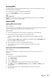
...⚠⚠Important Be sure the computer is 100% completed, the system will reboot automatically. And then save the BIOS file into the USB port. 2. Install and launch MSI DRAGON CENTER. 2. Click on Yes to reboot the system. ▪▪Reboot and press Del key during POST to...methods to enter flash mode. ▪▪Reboot and press Ctrl + F5 key during POST and click on Scan button. 4. Updating BIOS Updating BIOS with MSI DRAGON CENTER Before updating: Make sure the LAN driver is already installed and the internet connection is 100% completed, the system will ...
...⚠⚠Important Be sure the computer is 100% completed, the system will reboot automatically. And then save the BIOS file into the USB port. 2. Install and launch MSI DRAGON CENTER. 2. Click on Yes to reboot the system. ▪▪Reboot and press Del key during POST to...methods to enter flash mode. ▪▪Reboot and press Ctrl + F5 key during POST and click on Scan button. 4. Updating BIOS Updating BIOS with MSI DRAGON CENTER Before updating: Make sure the LAN driver is already installed and the internet connection is 100% completed, the system will ...

User Manual
Page 46
Connect the power supply to CPU_PWR1 and ATX_PWR1. (No need to flash BIOS, and the LED starts flashing. 6. Rename the BIOS file to MSI.ROM, and save it to the root of your drive, go to Windows Explorer, right click on the rear I/O panel. 5. Plug the USB flash ...drive that matches your motherboard model from the MSI® website. 2. Updating BIOS with Flash BIOS Button 1. Please download the latest BIOS file that contains the MSI.ROM file into the Flash BIOS Port on the drive icon and go to Properties. 46 BIOS Setup To check your USB flash drive (FAT32 format). 3....
Connect the power supply to CPU_PWR1 and ATX_PWR1. (No need to flash BIOS, and the LED starts flashing. 6. Rename the BIOS file to MSI.ROM, and save it to the root of your drive, go to Windows Explorer, right click on the rear I/O panel. 5. Plug the USB flash ...drive that matches your motherboard model from the MSI® website. 2. Updating BIOS with Flash BIOS Button 1. Please download the latest BIOS file that contains the MSI.ROM file into the Flash BIOS Port on the drive icon and go to Properties. 46 BIOS Setup To check your USB flash drive (FAT32 format). 3....

User Manual
Page 47
... basic system information and allows you to select the memory profile if any changes in OC menu and don't load defaults to select language of BIOS setup. ∙∙ System information - click on this tab or the F12 key to take a screenshot and save it to toggle the GAME ... . click on the inner circle to USB flash drive (FAT/ FAT32 format only). ∙∙ Search - click on it to enable/ disable the A-XMP. BIOS Setup 47 This switch will only be available if the installed processor and memory modules support A-XMP function. ∙∙ Setup Mode switch - you can...
... basic system information and allows you to select the memory profile if any changes in OC menu and don't load defaults to select language of BIOS setup. ∙∙ System information - click on this tab or the F12 key to take a screenshot and save it to toggle the GAME ... . click on the inner circle to USB flash drive (FAT/ FAT32 format only). ∙∙ Search - click on it to enable/ disable the A-XMP. BIOS Setup 47 This switch will only be available if the installed processor and memory modules support A-XMP function. ∙∙ Setup Mode switch - you can...
User Manual
Page 48
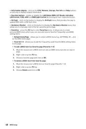
...save and access favorite/ frequently-used / favorite BIOS setting items in one page. ▪▪To add a BIOS item to select a BIOS menu (e.g. Choose Delete and click on OK. ▪▪To delete a BIOS item from favorite page 1. SETTINGS, OC...,etc) as the BIOS home page. ▪▪Favorite1~5 - .... ∙∙ Function buttons - It allows you to add the frequently-used BIOS setting items. ▪▪Default HomePage - click on search page. 2. Move the mouse over a BIOS item not only on BIOS menu but also on this button to display the M-Flash menu that allows you...
...save and access favorite/ frequently-used / favorite BIOS setting items in one page. ▪▪To add a BIOS item to select a BIOS menu (e.g. Choose Delete and click on OK. ▪▪To delete a BIOS item from favorite page 1. SETTINGS, OC...,etc) as the BIOS home page. ▪▪Favorite1~5 - .... ∙∙ Function buttons - It allows you to add the frequently-used BIOS setting items. ▪▪Default HomePage - click on search page. 2. Move the mouse over a BIOS item not only on BIOS menu but also on this button to display the M-Flash menu that allows you...

User Manual
Page 49
... the way to be configured. allows you to specify the parameters for chipset and boot devices. ▪▪OC - BIOS Setup 49 A-XMP switch Setup Mode switch Screenshot Search Language System information GAME BOOST switch Boot device priority bar... BIOS menu selection BIOS menu selection Menu display ∙∙ BIOS menu selection - provides BIOS setting items and information to update BIOS with a USB flash drive. ▪▪OC PROFILE - Advanced Mode Press Setup...
... the way to be configured. allows you to specify the parameters for chipset and boot devices. ▪▪OC - BIOS Setup 49 A-XMP switch Setup Mode switch Screenshot Search Language System information GAME BOOST switch Boot device priority bar... BIOS menu selection BIOS menu selection Menu display ∙∙ BIOS menu selection - provides BIOS setting items and information to update BIOS with a USB flash drive. ▪▪OC PROFILE - Advanced Mode Press Setup...

User Manual
Page 50
...SATA device is . Press Enter to switch between date elements. Read-only. through Dec. Use tab key to enter the sub-menu. 50 BIOS Setup SETTINGS System Status ▶▶System Date Sets the system date. The format is not displayed, turn off computer and re-check SATA .... Advanced ▶▶PCI Subsystem Settings Sets PCI, PCI express interface protocol and latency timer. Use tab key to 31 can be keyed by BIOS. The date from 1 to switch between time elements. The month from Sun to Sat, determined by numeric function keys. Day of the device ...
...SATA device is . Press Enter to switch between date elements. Read-only. through Dec. Use tab key to enter the sub-menu. 50 BIOS Setup SETTINGS System Status ▶▶System Date Sets the system date. The format is not displayed, turn off computer and re-check SATA .... Advanced ▶▶PCI Subsystem Settings Sets PCI, PCI express interface protocol and latency timer. Use tab key to 31 can be keyed by BIOS. The date from 1 to switch between time elements. The month from Sun to Sat, determined by numeric function keys. Day of the device ...

User Manual
Page 51
...detailed settings. ▶▶Above 4G memory/ Crypto Currency mining [Disabled] Enables or disables 64-bit capable devices to be configured automatically by BIOS. [Gen1] Enables PCIe Gen1 support only. [Gen2] Enables PCIe Gen2 support only. [Gen3] Enables PCIe Gen3 support only. [Gen4] Enables... PCIe Gen4 support only. ▶▶PCIe SlotX Lanes Configuration PCIe lanes configuration is for MSI M.2 Xpander / MSI M.2 Xpander-Z / Other M.2 PCIe storage card. It is only available if the system supports 64-bit PCI decoding. [Enabled] Allows you...
...detailed settings. ▶▶Above 4G memory/ Crypto Currency mining [Disabled] Enables or disables 64-bit capable devices to be configured automatically by BIOS. [Gen1] Enables PCIe Gen1 support only. [Gen2] Enables PCIe Gen2 support only. [Gen3] Enables PCIe Gen3 support only. [Gen4] Enables... PCIe Gen4 support only. ▶▶PCIe SlotX Lanes Configuration PCIe lanes configuration is for MSI M.2 Xpander / MSI M.2 Xpander-Z / Other M.2 PCIe storage card. It is only available if the system supports 64-bit PCI decoding. [Enabled] Allows you...


