User Manual
Page 13
... JTPM1: TPM Module Connector 35 CPU_FAN1, PUMP_FAN1, SYS_FAN1~6: Fan Connectors 36 JCI1: Chassis Intrusion Connector 37 JCOM1: Serial Port Connector 38 JBAT1: Clear CMOS (Reset BIOS) Jumper 38 Contents 13
... JTPM1: TPM Module Connector 35 CPU_FAN1, PUMP_FAN1, SYS_FAN1~6: Fan Connectors 36 JCI1: Chassis Intrusion Connector 37 JCOM1: Serial Port Connector 38 JBAT1: Clear CMOS (Reset BIOS) Jumper 38 Contents 13
User Manual
Page 14
... LED Control 41 Installing OS, Drivers & Utilities 42 Installing Windows® 10 42 Installing Drivers 42 Installing Utilities 42 UEFI BIOS...43 BIOS Setup...44 Entering BIOS Setup 44 Resetting BIOS...45 Updating BIOS...45 EZ Mode...47 Advanced Mode ...50 SETTINGS Menu...51 OC Menu...53 M-FLASH Menu...55 OC PROFILE Menu 56 HARDWARE...
... LED Control 41 Installing OS, Drivers & Utilities 42 Installing Windows® 10 42 Installing Drivers 42 Installing Utilities 42 UEFI BIOS...43 BIOS Setup...44 Entering BIOS Setup 44 Resetting BIOS...45 Updating BIOS...45 EZ Mode...47 Advanced Mode ...50 SETTINGS Menu...51 OC Menu...53 M-FLASH Menu...55 OC PROFILE Menu 56 HARDWARE...
User Manual
Page 15
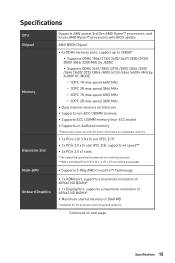
... Chipset Memory Expansion Slot Multi-GPU Onboard Graphics Supports AM4 socket 3rd Gen AMD Ryzen™ processors, and future AMD Ryzen™ processors with BIOS update AMD B550 Chipset ∙∙4x DDR4 memory slots, support up to 128GB* ▪▪Supports DDR4 1866/ 2133/ 2400/ 2667/ 2800/ 2933/ 3000/ 3066/ 3200... ∙∙Supports non-ECC UDIMM memory ∙∙Supports ECC UDIMM memory (non-ECC mode) ∙∙Supports un-buffered memory * Please refer www.msi.com for the processor with integrated graphics.
... Chipset Memory Expansion Slot Multi-GPU Onboard Graphics Supports AM4 socket 3rd Gen AMD Ryzen™ processors, and future AMD Ryzen™ processors with BIOS update AMD B550 Chipset ∙∙4x DDR4 memory slots, support up to 128GB* ▪▪Supports DDR4 1866/ 2133/ 2400/ 2667/ 2800/ 2933/ 3000/ 3066/ 3200... ∙∙Supports non-ECC UDIMM memory ∙∙Supports ECC UDIMM memory (non-ECC mode) ∙∙Supports un-buffered memory * Please refer www.msi.com for the processor with integrated graphics.
User Manual
Page 17
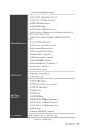
... Clear CMOS jumper LED Features ∙∙1x EZ LED Control switch ∙∙4x EZ Debug LED Back Panel Connectors ∙∙1x Flash BIOS Button ∙∙1x PS/2 keyboard/ mouse combo port ∙∙4x USB 2.0 Type-A ports ∙∙1x Display port ∙∙1x HDMI port...
... Clear CMOS jumper LED Features ∙∙1x EZ LED Control switch ∙∙4x EZ Debug LED Back Panel Connectors ∙∙1x Flash BIOS Button ∙∙1x PS/2 keyboard/ mouse combo port ∙∙4x USB 2.0 Type-A ports ∙∙1x Display port ∙∙1x HDMI port...
User Manual
Page 18
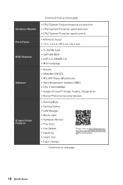
...flash ∙∙UEFI AMI BIOS ∙∙ACPI 6.0, SMBIOS 2.8 ∙∙ Multi-language ∙∙ Drivers ∙∙DRAGON CENTER ∙∙MSI APP Player (BlueStacks) ∙∙Open Broadcaster Software (OBS) ∙∙CPU-Z MSI GAMING ∙∙Google Chrome&#...8482;, Google Toolbar, Google Drive ∙∙Norton™ Internet Security Solution ∙∙Gaming Mode ∙∙Gaming Hotkey ∙∙LAN Manager ∙∙Mystic Light...
...flash ∙∙UEFI AMI BIOS ∙∙ACPI 6.0, SMBIOS 2.8 ∙∙ Multi-language ∙∙ Drivers ∙∙DRAGON CENTER ∙∙MSI APP Player (BlueStacks) ∙∙Open Broadcaster Software (OBS) ∙∙CPU-Z MSI GAMING ∙∙Google Chrome&#...8482;, Google Toolbar, Google Drive ∙∙Norton™ Internet Security Solution ∙∙Gaming Mode ∙∙Gaming Hotkey ∙∙LAN Manager ∙∙Mystic Light...
User Manual
Page 19
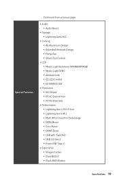
...;▪Lightning Gen 4 PCI-E Slot ▪▪Lightning Gen 4 M.2 ▪▪Multi GPU-CrossFire Technology ▪▪DDR4 Boost ▪▪Core Boost ▪▪GAME Boost ▪▪USB with Type A+C ▪▪USB 3.2 Gen 2 ▪▪Front USB Type-C ∙∙ Experience ▪▪Dragon Center ▪▪Click...
...;▪Lightning Gen 4 PCI-E Slot ▪▪Lightning Gen 4 M.2 ▪▪Multi GPU-CrossFire Technology ▪▪DDR4 Boost ▪▪Core Boost ▪▪GAME Boost ▪▪USB with Type A+C ▪▪USB 3.2 Gen 2 ▪▪Front USB Type-C ∙∙ Experience ▪▪Dragon Center ▪▪Click...

User Manual
Page 22
... Orange 10 Mbps connection 100 Mbps connection 1 Gbps connection Audio Ports Configuration 22 Rear I /O Panel PS/2 Combo port Flash BIOS Button DisplayPort USB 3.2 Gen 2 (10Gbps) Type-A Audio Ports 1 Gbps LAN Flash BIOS Port USB 2.0 Type-A USB 3.2 Gen 1 (5Gbps) Type-A Optical S/PDIF-Out USB 2.0 Type-A USB 3.2 Gen 2... (10Gbps) Type-C ∙∙ Flash BIOS Port/ Button - Rear I /O Panel Audio Ports Channel 2468 Center/ Sub-woofer Out ●● Rear Speaker Out ●●● Line...
... Orange 10 Mbps connection 100 Mbps connection 1 Gbps connection Audio Ports Configuration 22 Rear I /O Panel PS/2 Combo port Flash BIOS Button DisplayPort USB 3.2 Gen 2 (10Gbps) Type-A Audio Ports 1 Gbps LAN Flash BIOS Port USB 2.0 Type-A USB 3.2 Gen 1 (5Gbps) Type-A Optical S/PDIF-Out USB 2.0 Type-A USB 3.2 Gen 2... (10Gbps) Type-C ∙∙ Flash BIOS Port/ Button - Rear I /O Panel Audio Ports Channel 2468 Center/ Sub-woofer Out ●● Rear Speaker Out ●●● Line...
User Manual
Page 26
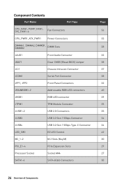
... Port Type CPU_FAN1, PUMP_FAN1, SYS_FAN1~6 Fan Connectors CPU_PWR1, ATX_PWR1 Power Connectors DIMMA1, DIMMA2, DIMMB1, DIMMB2 DIMM Slots JAUD1 Front Audio Connector JBAT1 Clear CMOS (Reset BIOS) Jumper JCI1 Chassis Intrusion Connector JCOM1 Serial Port Connector JFP1, JFP2 Front Panel Connectors JRAINBOW1~2 Addressable RGB LED connectors JRGB1 RGB LED connector JTPM1 TPM...
... Port Type CPU_FAN1, PUMP_FAN1, SYS_FAN1~6 Fan Connectors CPU_PWR1, ATX_PWR1 Power Connectors DIMMA1, DIMMA2, DIMMB1, DIMMB2 DIMM Slots JAUD1 Front Audio Connector JBAT1 Clear CMOS (Reset BIOS) Jumper JCI1 Chassis Intrusion Connector JCOM1 Serial Port Connector JFP1, JFP2 Front Panel Connectors JRAINBOW1~2 Addressable RGB LED connectors JRGB1 RGB LED connector JTPM1 TPM...
User Manual
Page 27
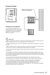
...Be sure to apply an even layer of the AM4 CPU has a yellow triangle to assist in the heatsink/ cooler package for motherboard placement. MSI® does not guarantee the damages or risks caused by inadequate operation beyond product specifications is the Pin 1 indicator. ⚠⚠Important ∙&#...8729;When changing the processor, the system configuration could be cleared and reset BIOS to default values, due to support overclocking. Overview of Components 27 The yellow triangle is not recommended.
...Be sure to apply an even layer of the AM4 CPU has a yellow triangle to assist in the heatsink/ cooler package for motherboard placement. MSI® does not guarantee the damages or risks caused by inadequate operation beyond product specifications is the Pin 1 indicator. ⚠⚠Important ∙&#...8729;When changing the processor, the system configuration could be cleared and reset BIOS to default values, due to support overclocking. Overview of Components 27 The yellow triangle is not recommended.
User Manual
Page 28
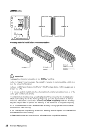
Go to BIOS and find the DRAM Frequency to set the memory frequency if you want to operate the memory at the marked or at a lower frequency than ... or overclocking. ∙∙The stability and compatibility of installed memory module depend on installed CPU and devices when overclocking. ∙∙Please refer www.msi.com for Dual channel mode, memory modules must be of Components
Go to BIOS and find the DRAM Frequency to set the memory frequency if you want to operate the memory at the marked or at a lower frequency than ... or overclocking. ∙∙The stability and compatibility of installed memory module depend on installed CPU and devices when overclocking. ∙∙Please refer www.msi.com for Dual channel mode, memory modules must be of Components
User Manual
Page 36
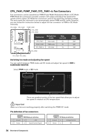
PWM Mode fan connectors provide constant 12V output and adjust fan speed with speed control signal. However, you to adjust fan speed in BIOS > HARDWARE MONITOR. power 24W 36W 12W SYS_FAN3 SYS_FAN5 SYS_FAN4 Switching fan mode and adjusting fan speed You can switch between PWM mode and DC mode ...
PWM Mode fan connectors provide constant 12V output and adjust fan speed with speed control signal. However, you to adjust fan speed in BIOS > HARDWARE MONITOR. power 24W 36W 12W SYS_FAN3 SYS_FAN5 SYS_FAN4 Switching fan mode and adjusting fan speed You can switch between PWM mode and DC mode ...
User Manual
Page 37
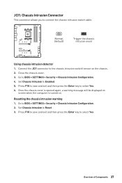
... F10 to save and exit and then press the Enter key to select Yes. JCI1: Chassis Intrusion Connector This connector allows you to BIOS > SETTINGS > Security > Chassis Intrusion Configuration. 4. Once the chassis cover is opened again, a warning message will be displayed on screen... 37 Press F10 to save and exit and then press the Enter key to select Yes. 6. Go to Reset. 3. Set Chassis Intrusion to BIOS > SETTINGS > Security > Chassis Intrusion Configuration. 2. Close the chassis cover. 3. Normal (default) Trigger the chassis intrusion event Using chassis intrusion ...
... F10 to save and exit and then press the Enter key to select Yes. JCI1: Chassis Intrusion Connector This connector allows you to BIOS > SETTINGS > Security > Chassis Intrusion Configuration. 4. Once the chassis cover is opened again, a warning message will be displayed on screen... 37 Press F10 to save and exit and then press the Enter key to select Yes. 6. Go to Reset. 3. Set Chassis Intrusion to BIOS > SETTINGS > Security > Chassis Intrusion Configuration. 2. Close the chassis cover. 3. Normal (default) Trigger the chassis intrusion event Using chassis intrusion ...
User Manual
Page 38
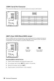
... to connect the optional serial port with bracket. 2 10 1 9 1 DCD 2 SIN 3 SOUT 4 DTR 5 Ground 6 DSR 7 RTS 8 CTS 9 RI 10 No Pin JBAT1: Clear CMOS (Reset BIOS) Jumper There is CMOS memory onboard that is external powered from JBAT1. 4. Keep Data (default) Clear CMOS/ Reset...
... to connect the optional serial port with bracket. 2 10 1 9 1 DCD 2 SIN 3 SOUT 4 DTR 5 Ground 6 DSR 7 RTS 8 CTS 9 RI 10 No Pin JBAT1: Clear CMOS (Reset BIOS) Jumper There is CMOS memory onboard that is external powered from JBAT1. 4. Keep Data (default) Clear CMOS/ Reset...
User Manual
Page 43
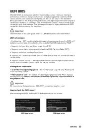
UEFI BIOS MSI UEFI BIOS is no malware tampers with the startup process. UEFI has many new functions and advantages that traditional BIOS cannot achieve, and it still has a CSM (Compatibility Support Module) mode to be compatible with UEFI compatible devices during POST. ... 2 TB. ∙∙Supports more than 4 primary partitions with UEFI (Unified Extensible Firmware Interface) architecture. The MSI UEFI BIOS uses UEFI as the default boot mode to UEFI BIOS unless otherwise noted. Incompatible UEFI cases ∙∙ 32-bit Windows operating system - How to ensure that you ...
UEFI BIOS MSI UEFI BIOS is no malware tampers with the startup process. UEFI has many new functions and advantages that traditional BIOS cannot achieve, and it still has a CSM (Compatibility Support Module) mode to be compatible with UEFI compatible devices during POST. ... 2 TB. ∙∙Supports more than 4 primary partitions with UEFI (Unified Extensible Firmware Interface) architecture. The MSI UEFI BIOS uses UEFI as the default boot mode to UEFI BIOS unless otherwise noted. Incompatible UEFI cases ∙∙ 32-bit Windows operating system - How to ensure that you ...

User Manual
Page 44
...Specifications menu F5: Enter Memory-Z menu F6: Load optimized defaults F7: Switch between Yes or No to confirm your choice. 44 UEFI BIOS Ctrl+F: Enter Search page * When you press F10, a confirmation window appears and it to USB flash drive (FAT/ FAT32 format only...be slightly different from the product you purchased. ∙∙The BIOS items will vary with BIOS. ⚠⚠Important ∙∙BIOS items are continuously update for reference only. Therefore, the description may vary from the latest BIOS and should always keep the default settings to avoid possible system ...
...Specifications menu F5: Enter Memory-Z menu F6: Load optimized defaults F7: Switch between Yes or No to confirm your choice. 44 UEFI BIOS Ctrl+F: Enter Search page * When you press F10, a confirmation window appears and it to USB flash drive (FAT/ FAT32 format only...be slightly different from the product you purchased. ∙∙The BIOS items will vary with BIOS. ⚠⚠Important ∙∙BIOS items are continuously update for reference only. Therefore, the description may vary from the latest BIOS and should always keep the default settings to avoid possible system ...
User Manual
Page 45
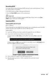
...Yes to reboot the system. Updating BIOS: 1. Select a BIOS file to reboot the system. 3. UEFI BIOS 45 Click the M-FLASH button and click on Yes to perform the BIOS update process. 4. Insert the USB flash drive that matches your motherboard model from MSI website. Please refer the following ...methods to enter flash mode. ▪▪Reboot and press Ctrl + F5 key during POST to enter BIOS. Resetting BIOS You might need to restore the default BIOS setting to solve certain problems. There ...
...Yes to reboot the system. Updating BIOS: 1. Select a BIOS file to reboot the system. 3. UEFI BIOS 45 Click the M-FLASH button and click on Yes to perform the BIOS update process. 4. Insert the USB flash drive that matches your motherboard model from MSI website. Please refer the following ...methods to enter flash mode. ▪▪Reboot and press Ctrl + F5 key during POST to enter BIOS. Resetting BIOS You might need to restore the default BIOS setting to solve certain problems. There ...
User Manual
Page 46
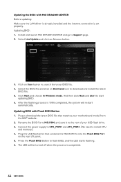
...5. Click on Download icon to Support page. 2. Updating BIOS with MSI DRAGON CENTER Before updating: Make sure the LAN driver is already installed and the internet connection is completed. 46 UEFI BIOS Press the Flash BIOS Button to start updating BIOS. 6. Click Next and choose In Windows mode. And ... and click on Scan button to the root of your motherboard model from the MSI® website. 2. Install and launch MSI DRAGON CENTER and go to download and install the latest BIOS file. 5. Updating BIOS: 1. After the flashing process is 100% completed, the system will be turned...
...5. Click on Download icon to Support page. 2. Updating BIOS with MSI DRAGON CENTER Before updating: Make sure the LAN driver is already installed and the internet connection is completed. 46 UEFI BIOS Press the Flash BIOS Button to start updating BIOS. 6. Click Next and choose In Windows mode. And ... and click on Scan button to the root of your motherboard model from the MSI® website. 2. Install and launch MSI DRAGON CENTER and go to download and install the latest BIOS file. 5. Updating BIOS: 1. After the flashing process is 100% completed, the system will be turned...

User Manual
Page 47
...EZ mode. ∙∙ Screenshot - This function is only available when both of BIOS setup. click on this function. ⚠⚠Important We don't recommend you to adjust any BIOS item after activating the GAME BOOST function for keeping the optimal performance and system stability. ∙∙ A-XMP ...F12 function keys are supporting this tab or the F12 key to take a screenshot and save it to toggle the GAME BOOST for memory to overclock. UEFI BIOS 47 click on it to configure the basic setting. allows you to select the A-XMP profile for overclocking. EZ ...
...EZ mode. ∙∙ Screenshot - This function is only available when both of BIOS setup. click on this function. ⚠⚠Important We don't recommend you to adjust any BIOS item after activating the GAME BOOST function for keeping the optimal performance and system stability. ∙∙ A-XMP ...F12 function keys are supporting this tab or the F12 key to take a screenshot and save it to toggle the GAME BOOST for memory to overclock. UEFI BIOS 47 click on it to configure the basic setting. allows you to select the A-XMP profile for overclocking. EZ ...
User Manual
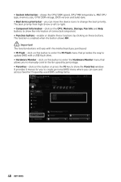
Page 48
...priority. enable or disable these buttons. shows the CPU/ DDR speed, CPU/ MB temperature, MB/ CPU type, memory size, CPU/ DDR voltage, BIOS version and build date. ∙∙ Boot device priority bar - click on this button to enter the M-Flash menu that allows you can save ...and access favorite/ frequently-used BIOS setting items. 48 UEFI BIOS ∙∙ System information - click on this button to enter the Hardware Monitor menu that provides the way to create personal...
...priority. enable or disable these buttons. shows the CPU/ DDR speed, CPU/ MB temperature, MB/ CPU type, memory size, CPU/ DDR voltage, BIOS version and build date. ∙∙ Boot device priority bar - click on this button to enter the M-Flash menu that allows you can save ...and access favorite/ frequently-used BIOS setting items. 48 UEFI BIOS ∙∙ System information - click on this button to enter the Hardware Monitor menu that provides the way to create personal...

User Manual
Page 49
Right-click or press F2 key. 3. Choose a favorite page and click on favorite menu. 2. Select a BIOS item on OK. ▪▪To delete a BIOS item from favorite menu 1. Right-click or press F2 key. 3. Choose Delete and click on search page. 2. UEFI BIOS 49 ▪▪To add a BIOS item to a favorite menu 1. Select a BIOS item not only on BIOS menu but also on OK.
Right-click or press F2 key. 3. Choose a favorite page and click on favorite menu. 2. Select a BIOS item on OK. ▪▪To delete a BIOS item from favorite menu 1. Right-click or press F2 key. 3. Choose Delete and click on search page. 2. UEFI BIOS 49 ▪▪To add a BIOS item to a favorite menu 1. Select a BIOS item not only on BIOS menu but also on OK.


