User Manual
Page 1
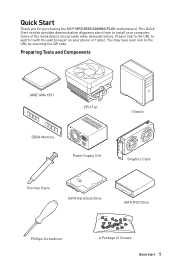
... Components AMD® AM4 CPU CPU Fan DDR4 Memory Power Supply Unit Chassis Graphics Card Thermal Paste SATA Hard Disk Drive SATA DVD Drive Phillips Screwdriver A Package of the installations also provide video demonstrations. Please link to the URL to the URL by scanning the QR code. This Quick Start section provides demonstration diagrams about how to install your phone or t ablet. Some of Screws Quick Start 1 Quick Start Thank you for purchasing the MSI® MPG B550 GAMING PLUS motherboard.
... Components AMD® AM4 CPU CPU Fan DDR4 Memory Power Supply Unit Chassis Graphics Card Thermal Paste SATA Hard Disk Drive SATA DVD Drive Phillips Screwdriver A Package of the installations also provide video demonstrations. Please link to the URL to the URL by scanning the QR code. This Quick Start section provides demonstration diagrams about how to install your phone or t ablet. Some of Screws Quick Start 1 Quick Start Thank you for purchasing the MSI® MPG B550 GAMING PLUS motherboard.
User Manual
Page 13
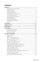
... Processor 3 Installing DDR4 memory 5 Connecting the Front Panel Header 6 Installing the Motherboard 7 Connecting the Power Connectors 8 Installing SATA Drives 9 Installing a Graphics Card 10 Connecting Peripheral Devices 11 Power On...12 Specifications...15 Package contents 20 Block Diagram ...21 Rear I/O Panel...22 LAN Port LED Status Table 22 Audio Ports Configuration 22 Realtek Audio Console 23 Overview of Components 25 Processor Socket 27 DIMM Slots...28 PCI_E1~4: PCIe Expansion Slots 29 SATA1~6: SATA 6Gb/s Connectors 30 M2_1~2: M.2 Slots (Key M 30 JFP1, JFP2: Front Panel...
... Processor 3 Installing DDR4 memory 5 Connecting the Front Panel Header 6 Installing the Motherboard 7 Connecting the Power Connectors 8 Installing SATA Drives 9 Installing a Graphics Card 10 Connecting Peripheral Devices 11 Power On...12 Specifications...15 Package contents 20 Block Diagram ...21 Rear I/O Panel...22 LAN Port LED Status Table 22 Audio Ports Configuration 22 Realtek Audio Console 23 Overview of Components 25 Processor Socket 27 DIMM Slots...28 PCI_E1~4: PCIe Expansion Slots 29 SATA1~6: SATA 6Gb/s Connectors 30 M2_1~2: M.2 Slots (Key M 30 JFP1, JFP2: Front Panel...
User Manual
Page 14
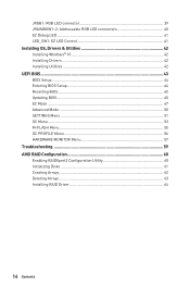
... RGB LED connectors 40 EZ Debug LED...41 LED_SW1: EZ LED Control 41 Installing OS, Drivers & Utilities 42 Installing Windows® 10 42 Installing Drivers 42 Installing Utilities 42 UEFI BIOS...43 BIOS Setup...44 Entering BIOS Setup 44 Resetting BIOS...45 Updating BIOS...45 EZ Mode...47 Advanced Mode ...50 SETTINGS Menu...51 OC Menu...53 M-FLASH Menu...55 OC PROFILE Menu 56 HARDWARE MONITOR Menu 57 Troubleshooting 59 AMD RAID Configuration 60 Enabling RAIDXpert2 Configuration Utility 60 Initializing Disks...61 Creating Arrays...62 Deleting Arrays...63 Installing RAID Driver 64...
... RGB LED connectors 40 EZ Debug LED...41 LED_SW1: EZ LED Control 41 Installing OS, Drivers & Utilities 42 Installing Windows® 10 42 Installing Drivers 42 Installing Utilities 42 UEFI BIOS...43 BIOS Setup...44 Entering BIOS Setup 44 Resetting BIOS...45 Updating BIOS...45 EZ Mode...47 Advanced Mode ...50 SETTINGS Menu...51 OC Menu...53 M-FLASH Menu...55 OC PROFILE Menu 56 HARDWARE MONITOR Menu 57 Troubleshooting 59 AMD RAID Configuration 60 Enabling RAIDXpert2 Configuration Utility 60 Initializing Disks...61 Creating Arrays...62 Deleting Arrays...63 Installing RAID Driver 64...
User Manual
Page 15
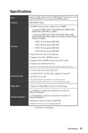
...;∙Supports un-buffered memory * Please refer www.msi.com for more information on compatible memory. ∙∙1x PCIe 4.0/ 3.0 x16 slot (PCI_E1)* ∙∙1x PCIe 3.0 x16 slot (PCI_E3), supports x4 speed** ∙∙2x PCIe 3.0 x1 slots * The supported specification depends on next page Specifications 15 Continued on installed processor. ** When installing PCIe SSD in M.2_2, PCI_E3 slot will be unavailable. ∙∙Supports 2-Way AMD CrossFire™ Technology ∙∙1x HDMI port, supports...
...;∙Supports un-buffered memory * Please refer www.msi.com for more information on compatible memory. ∙∙1x PCIe 4.0/ 3.0 x16 slot (PCI_E1)* ∙∙1x PCIe 3.0 x16 slot (PCI_E3), supports x4 speed** ∙∙2x PCIe 3.0 x1 slots * The supported specification depends on next page Specifications 15 Continued on installed processor. ** When installing PCIe SSD in M.2_2, PCI_E3 slot will be unavailable. ∙∙Supports 2-Way AMD CrossFire™ Technology ∙∙1x HDMI port, supports...
User Manual
Page 18
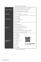
... 18 Specifications pdf for more details. Continued from previous page Hardware Monitor Form Factor BIOS Features Software Dragon Center Features ∙∙CPU/ System/ Chipset temperature detection ∙∙CPU/ System/ Pump fan speed detection ∙∙CPU/ System/ Pump fan speed control ∙∙ATX Form Factor ∙∙12 in . (30.5 cm x 24.4 cm) ∙∙1x 256 Mb flash ∙∙UEFI AMI BIOS ∙∙ACPI...
... 18 Specifications pdf for more details. Continued from previous page Hardware Monitor Form Factor BIOS Features Software Dragon Center Features ∙∙CPU/ System/ Chipset temperature detection ∙∙CPU/ System/ Pump fan speed detection ∙∙CPU/ System/ Pump fan speed control ∙∙ATX Form Factor ∙∙12 in . (30.5 cm x 24.4 cm) ∙∙1x 256 Mb flash ∙∙UEFI AMI BIOS ∙∙ACPI...
User Manual
Page 38
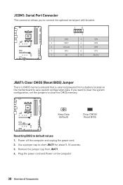
... (default) Clear CMOS/ Reset BIOS Resetting BIOS to short JBAT1 for about 5-10 seconds. 3. If you to connect the optional serial port with bracket. 2 10 1 9 1 DCD 2 SIN 3 SOUT 4 DTR 5 Ground 6 DSR 7 RTS 8 CTS 9 RI 10 No Pin JBAT1: Clear CMOS (Reset BIOS) Jumper There is CMOS memory onboard that is external powered from JBAT1. 4. Use a jumper cap to default values 1. Remove the jumper cap from a battery located on the computer. 38 Overview of Components Plug the power cord and Power on the motherboard...
... (default) Clear CMOS/ Reset BIOS Resetting BIOS to short JBAT1 for about 5-10 seconds. 3. If you to connect the optional serial port with bracket. 2 10 1 9 1 DCD 2 SIN 3 SOUT 4 DTR 5 Ground 6 DSR 7 RTS 8 CTS 9 RI 10 No Pin JBAT1: Clear CMOS (Reset BIOS) Jumper There is CMOS memory onboard that is external powered from JBAT1. 4. Use a jumper cap to default values 1. Remove the jumper cap from a battery located on the computer. 38 Overview of Components Plug the power cord and Power on the motherboard...
User Manual
Page 40
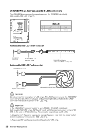
... JRAINBOW connector provide different voltages, and connecting the 5V LED strip to the JRGB connector will result in damage to the LED strip. ⚠⚠Important ∙∙The JRAINBOW connector supports up to 200 LEDs. ∙∙Always turn off the power supply and unplug the power cord from the power outlet before installing or removing the RGB LED strip. ∙∙Please use MSI's software to 75 LEDs WS2812B...
... JRAINBOW connector provide different voltages, and connecting the 5V LED strip to the JRGB connector will result in damage to the LED strip. ⚠⚠Important ∙∙The JRAINBOW connector supports up to 200 LEDs. ∙∙Always turn off the power supply and unplug the power cord from the power outlet before installing or removing the RGB LED strip. ∙∙Please use MSI's software to 75 LEDs WS2812B...

User Manual
Page 42
... be in Windows® 10. 2. Installing OS, Drivers & Utilities Please download and update the latest utilities and drivers at www.msi.com Installing Windows® 10 1. Follow the instructions on the computer. 2. Click the Select to get into your computer. 3. Click the Install button in the Drivers/Software tab. 5. Restart your computer. 42 Installing OS, Drivers & Utilities Click the Utilities tab. 3. Restart your computer. Press F11 key during the computer POST (Power-On...
... be in Windows® 10. 2. Installing OS, Drivers & Utilities Please download and update the latest utilities and drivers at www.msi.com Installing Windows® 10 1. Follow the instructions on the computer. 2. Click the Select to get into your computer. 3. Click the Install button in the Drivers/Software tab. 5. Restart your computer. 42 Installing OS, Drivers & Utilities Click the Utilities tab. 3. Restart your computer. Press F11 key during the computer POST (Power-On...
User Manual
Page 45
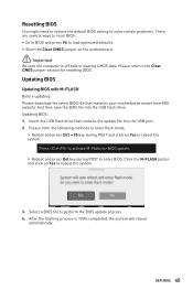
... the default BIOS setting to solve certain problems. There are several ways to reset BIOS: ∙∙Go to BIOS and press F6 to load optimized defaults. ∙∙Short the Clear CMOS jumper on the motherboard. ⚠⚠Important Be sure the computer is 100% completed, the system will reboot automatically. Please refer to perform the BIOS update process. 4. Insert the USB flash drive that matches your motherboard model from MSI...
... the default BIOS setting to solve certain problems. There are several ways to reset BIOS: ∙∙Go to BIOS and press F6 to load optimized defaults. ∙∙Short the Clear CMOS jumper on the motherboard. ⚠⚠Important Be sure the computer is 100% completed, the system will reboot automatically. Please refer to perform the BIOS update process. 4. Insert the USB flash drive that matches your motherboard model from MSI...
User Manual
Page 46
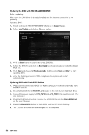
... will be turned off when the process is set properly. Connect the power supply to CPU_PWR1 and ATX_PWR1. (No need to Support page. 2. Click Next and choose In Windows mode. Plug the USB flash drive that matches your USB flash drive. 3. Install and launch MSI DRAGON CENTER and go to install CPU and memory.) 4. And then click Next and Start to flash BIOS, and the LED starts flashing. 6. The LED will restart automatically. Updating BIOS: 1. Select Live Update and click...
... will be turned off when the process is set properly. Connect the power supply to CPU_PWR1 and ATX_PWR1. (No need to Support page. 2. Click Next and choose In Windows mode. Plug the USB flash drive that matches your USB flash drive. 3. Install and launch MSI DRAGON CENTER and go to install CPU and memory.) 4. And then click Next and Start to flash BIOS, and the LED starts flashing. 6. The LED will restart automatically. Updating BIOS: 1. Select Live Update and click...
User Manual
Page 48
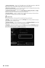
... CPU, Memory, Storage, Fan Info and Help buttons to manually control the fan speed by clicking on this button to enter the Hardware Monitor menu that provides the way to change the boot priority. click on this button or press the F3 key to right. ∙∙ Component Information - The boot priority from high to low is enabled when the button shows ON . ⚠⚠Important The function buttons will vary with a USB flash drive...
... CPU, Memory, Storage, Fan Info and Help buttons to manually control the fan speed by clicking on this button to enter the Hardware Monitor menu that provides the way to change the boot priority. click on this button or press the F3 key to right. ∙∙ Component Information - The boot priority from high to low is enabled when the button shows ON . ⚠⚠Important The function buttons will vary with a USB flash drive...
User Manual
Page 50
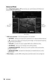
... the way to be configured. 50 UEFI BIOS allows you to set the speeds of fans and monitor voltages of installed devices on this motherboard. ∙∙ Menu display - Advanced Mode Press Setup Mode switch or F7 function key can switch between EZ Mode and Advanced Mode in BIOS setup. the following options are available: ▪▪SETTINGS - provides the information of system. ▪▪BOARD EXPLORER - provides BIOS setting items and information to update BIOS with a USB flash drive. ▪▪OC...
... the way to be configured. 50 UEFI BIOS allows you to set the speeds of fans and monitor voltages of installed devices on this motherboard. ∙∙ Menu display - Advanced Mode Press Setup Mode switch or F7 function key can switch between EZ Mode and Advanced Mode in BIOS setup. the following options are available: ▪▪SETTINGS - provides the information of system. ▪▪BOARD EXPLORER - provides BIOS setting items and information to update BIOS with a USB flash drive. ▪▪OC...
User Manual
Page 51
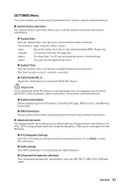
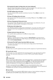
... PCIe, ACPI, integrated peripherals, integrated graphics, USB, power management and Windows . ▶▶PCI Subsystem Settings Sets PCI, PCI express interface protocol and latency timer. Use tab key to switch between date elements. The format is not displayed, turn off computer and re-check SATA/ M.2 cable and power cable connections of the device and motherboard. ▶▶System Information Shows detailed system information, including CPU type, BIOS version, and Memory (read only). ▶▶DMI Information Shows system information, desktop board...
... PCIe, ACPI, integrated peripherals, integrated graphics, USB, power management and Windows . ▶▶PCI Subsystem Settings Sets PCI, PCI express interface protocol and latency timer. Use tab key to switch between date elements. The format is not displayed, turn off computer and re-check SATA/ M.2 cable and power cable connections of the device and motherboard. ▶▶System Information Shows detailed system information, including CPU type, BIOS version, and Memory (read only). ▶▶DMI Information Shows system information, desktop board...
User Manual
Page 52
... factory default settings into the BIOS and exit the BIOS setup utility with IGP. ▶▶USB Configuration sub-menu Sets the onboard USB controller and device function. Please note that data of system boot devices. ▶▶Security sub-menu Use this menu. ▶▶Windows OS Configuration Sets Windows detailed configuration and behaviors. To clear a set the system boot states and the sequence of SSD will replace any previous set the administrator password and the user password for different sleep modes. ▶...
... factory default settings into the BIOS and exit the BIOS setup utility with IGP. ▶▶USB Configuration sub-menu Sets the onboard USB controller and device function. Please note that data of system boot devices. ▶▶Security sub-menu Use this menu. ▶▶Windows OS Configuration Sets Windows detailed configuration and behaviors. To clear a set the system boot states and the sequence of SSD will replace any previous set the administrator password and the user password for different sleep modes. ▶...
User Manual
Page 53
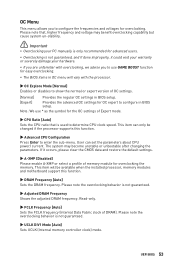
... unfamiliar with the processor. ▶▶OC Explore Mode [Normal] Enables or disables to show the normal or expert version of Expert mode. ▶▶CPU Ratio [Auto] Sets the CPU ratio that , higher frequency and voltage may become unstable or unbootable after changing the parameters. Please note the overclocking behavior is not guaranteed. ▶▶UCLK DIV1 Mode [Auto] Sets UCLK (Internal memory controller clock) mode. OC Menu This menu allows you to...
... unfamiliar with the processor. ▶▶OC Explore Mode [Normal] Enables or disables to show the normal or expert version of Expert mode. ▶▶CPU Ratio [Auto] Sets the CPU ratio that , higher frequency and voltage may become unstable or unbootable after changing the parameters. Please note the overclocking behavior is not guaranteed. ▶▶UCLK DIV1 Mode [Auto] Sets UCLK (Internal memory controller clock) mode. OC Menu This menu allows you to...

User Manual
Page 54
...;▶CPU Voltages control [Auto] These options allows you to set it occurs, please clear the CMOS data and restore the default settings. (Refer to the Clear CMOS jumper section to clear the CMOS data, and enter the BIOS to load the default settings.) ▶▶DigitALL Power sub-menu Press Enter to enter the sub-menu. The system may become unstable or unbootable after changing memory timing. This sub-menu displays all memory channel. If it manually. ▶▶Memory Changed Detect [Enabled]* Enables or disables...
...;▶CPU Voltages control [Auto] These options allows you to set it occurs, please clear the CMOS data and restore the default settings. (Refer to the Clear CMOS jumper section to clear the CMOS data, and enter the BIOS to load the default settings.) ▶▶DigitALL Power sub-menu Press Enter to enter the sub-menu. The system may become unstable or unbootable after changing memory timing. This sub-menu displays all memory channel. If it manually. ▶▶Memory Changed Detect [Enabled]* Enables or disables...
User Manual
Page 55
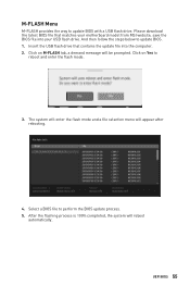
.... And then follow the steps below to reboot and enter the flash mode. 3. Insert the USB flash drive that matches your USB flash drive. The system will enter the flash mode and a file selection menu will appear after rebooting. 4. UEFI BIOS 55 Please download the latest BIOS file that contains the update file into your motherboard model from MSI website, save the BIOS file into the computer. 2. Select a BIOS file to update BIOS with a USB flash drive. M-FLASH Menu M-FLASH provides the way to perform the...
.... And then follow the steps below to reboot and enter the flash mode. 3. Insert the USB flash drive that matches your USB flash drive. The system will enter the flash mode and a file selection menu will appear after rebooting. 4. UEFI BIOS 55 Please download the latest BIOS file that contains the update file into your motherboard model from MSI website, save the BIOS file into the computer. 2. Select a BIOS file to update BIOS with a USB flash drive. M-FLASH Menu M-FLASH provides the way to perform the...
User Manual
Page 59
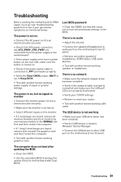
...;∙Connect the USB device to other USB port on the motherboard rear IO panel. ∙∙Remove secondary speakers/ headphones, HDMI cables, USB audio devices. ∙∙Test with another known working graphics card. The computer does not boot after updating the BIOS ∙∙Clear the CMOS. ∙∙Use the secondary BIOS to see if your USB drive driver has been installed. ∙∙Verify if USB device is properly connected and make sure the button is turned on the monitor...
...;∙Connect the USB device to other USB port on the motherboard rear IO panel. ∙∙Remove secondary speakers/ headphones, HDMI cables, USB audio devices. ∙∙Test with another known working graphics card. The computer does not boot after updating the BIOS ∙∙Clear the CMOS. ∙∙Use the secondary BIOS to see if your USB drive driver has been installed. ∙∙Verify if USB device is properly connected and make sure the button is turned on the monitor...
User Manual
Page 60
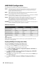
..., and then reboot and press Delete key to BIOS > SETTINGS > Advanced > RAIDXpert2 Configuration Utility submenu. 60 AMD RAID Configuration Go to enter BIOS Setup menu. 6. Spreading the hard drive I/O load across independent channels greatly improves I/O performance. RAID 1 (Mirroring) provides data redundancy by RAIDXpert2. RAIDABLE (also known as RAID Ready) allows the user to RAID Mode. 4. AMD RAID Configuration The following are written to separate hard drives. RAID level comparison RAID 0 RAID 1 RAID 10 Minimum # drives 2 2 4 Data protection None Excellent Excellent...
..., and then reboot and press Delete key to BIOS > SETTINGS > Advanced > RAIDXpert2 Configuration Utility submenu. 60 AMD RAID Configuration Go to enter BIOS Setup menu. 6. Spreading the hard drive I/O load across independent channels greatly improves I/O performance. RAID 1 (Mirroring) provides data redundancy by RAIDXpert2. RAIDABLE (also known as RAID Ready) allows the user to RAID Mode. 4. AMD RAID Configuration The following are written to separate hard drives. RAID level comparison RAID 0 RAID 1 RAID 10 Minimum # drives 2 2 4 Data protection None Excellent Excellent...

User Manual
Page 64
... the Windows Control Panel, you can still manually execute the DVDSetup. Click the Install button. 6. admin ▫▫Password - Insert the MSI Driver Disc into the RAIDXpert2 Web GUI with AMD RAID Drivers and then click Browse. ▪▪To make an AMD RAID Drivers USB flash drive. Select the (rcraid.inf) driver, click Next. 8. Set the SATA Mode to install a third party RAID driver. 2. Copy all the contents in BIOS 2. Windows setup will need to copy the files...
... the Windows Control Panel, you can still manually execute the DVDSetup. Click the Install button. 6. admin ▫▫Password - Insert the MSI Driver Disc into the RAIDXpert2 Web GUI with AMD RAID Drivers and then click Browse. ▪▪To make an AMD RAID Drivers USB flash drive. Select the (rcraid.inf) driver, click Next. 8. Set the SATA Mode to install a third party RAID driver. 2. Copy all the contents in BIOS 2. Windows setup will need to copy the files...


