
User Manual
Page 1
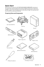
... you for purchasing the MSI® MPG Z490 GAMING CARBON WIFI motherboard. You may have even link to watch it with the web browser on your computer. Preparing Tools and Components Intel® LGA 1200 CPU CPU Fan DDR4 Memory Power Supply Unit Chassis Graphics Card Thermal Paste SATA Hard Disk Drive SATA DVD Drive Phillips Screwdriver A Package of the installations also provide video demonstrations. Please link to the URL to the URL...
... you for purchasing the MSI® MPG Z490 GAMING CARBON WIFI motherboard. You may have even link to watch it with the web browser on your computer. Preparing Tools and Components Intel® LGA 1200 CPU CPU Fan DDR4 Memory Power Supply Unit Chassis Graphics Card Thermal Paste SATA Hard Disk Drive SATA DVD Drive Phillips Screwdriver A Package of the installations also provide video demonstrations. Please link to the URL to the URL...
User Manual
Page 12
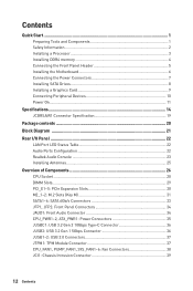
... a Processor 3 Installing DDR4 memory 4 Connecting the Front Panel Header 5 Installing the Motherboard 6 Connecting the Power Connectors 7 Installing SATA Drives 8 Installing a Graphics Card 9 Connecting Peripheral Devices 10 Power On...11 Specifications...14 JCORSAIR1 Connector Specification 19 Package contents 20 Block Diagram ...21 Rear I/O Panel ...22 LAN Port LED Status Table 22 Audio Ports Configuration 22 Realtek Audio Console 23 Installing Antennas 25 Overview of Components 26 CPU Socket ...28 DIMM Slots...29 PCI_E1~5: PCIe Expansion Slots 30 M2_1~2: M.2 Slots (Key...
... a Processor 3 Installing DDR4 memory 4 Connecting the Front Panel Header 5 Installing the Motherboard 6 Connecting the Power Connectors 7 Installing SATA Drives 8 Installing a Graphics Card 9 Connecting Peripheral Devices 10 Power On...11 Specifications...14 JCORSAIR1 Connector Specification 19 Package contents 20 Block Diagram ...21 Rear I/O Panel ...22 LAN Port LED Status Table 22 Audio Ports Configuration 22 Realtek Audio Console 23 Installing Antennas 25 Overview of Components 26 CPU Socket ...28 DIMM Slots...29 PCI_E1~5: PCIe Expansion Slots 30 M2_1~2: M.2 Slots (Key...
User Manual
Page 13
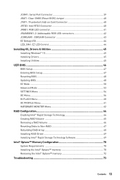
... Windows® 10 45 Installing Drivers 45 Installing Utilities 45 UEFI BIOS...46 BIOS Setup...47 Entering BIOS Setup 47 Resetting BIOS...48 Updating BIOS...48 EZ Mode ...50 Advanced Mode ...53 SETTINGS Menu 54 OC Menu...56 M-FLASH Menu ...60 OC PROFILE Menu 61 HARDWARE MONITOR Menu 62 RAID Configuration 64 Enabling Intel® Rapid Storage Technology 64 Creating RAID Volume 65 Removing a RAID Volume 66 Resetting Disks to Non-RAID 67 Rebuilding RAID Array 68 Installing RAID Driver 69 Installing Intel® Rapid Storage Technology Software 69 Intel® Optane™ Memory...
... Windows® 10 45 Installing Drivers 45 Installing Utilities 45 UEFI BIOS...46 BIOS Setup...47 Entering BIOS Setup 47 Resetting BIOS...48 Updating BIOS...48 EZ Mode ...50 Advanced Mode ...53 SETTINGS Menu 54 OC Menu...56 M-FLASH Menu ...60 OC PROFILE Menu 61 HARDWARE MONITOR Menu 62 RAID Configuration 64 Enabling Intel® Rapid Storage Technology 64 Creating RAID Volume 65 Removing a RAID Volume 66 Resetting Disks to Non-RAID 67 Rebuilding RAID Array 68 Installing RAID Driver 69 Installing Intel® Rapid Storage Technology Software 69 Intel® Optane™ Memory...
User Manual
Page 40
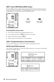
... motherboard to connect the add-on Thunderbolt I /O card. Power off the computer and unplug the power cord. 2. JBAT1: Clear CMOS (Reset BIOS) Jumper There is external powered from JBAT1. 4. JTBT1: Thunderbolt Add-on Card Connector This connector allows you to save system configuration data. JRTD3: Intel RTD3 Connector This connector allows you want to clear the system configuration, set the jumpers to connect the RTD3 connector on the add-on Thunderbolt I /O card that is CMOS memory onboard...
... motherboard to connect the add-on Thunderbolt I /O card. Power off the computer and unplug the power cord. 2. JBAT1: Clear CMOS (Reset BIOS) Jumper There is external powered from JBAT1. 4. JTBT1: Thunderbolt Add-on Card Connector This connector allows you to save system configuration data. JRTD3: Intel RTD3 Connector This connector allows you want to clear the system configuration, set the jumpers to connect the RTD3 connector on the add-on Thunderbolt I /O card that is CMOS memory onboard...
User Manual
Page 42
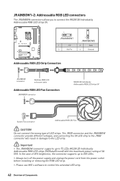
... JRAINBOW connector supports up to 200 LEDs. ∙∙Always turn off the power supply and unplug the power cord from the power outlet before installing or removing the RGB LED strip. ∙∙Please use MSI's software to 75 LEDs WS2812B Individually Addressable RGB LED strips (5V/Data/Ground) with the maximum power rating of LED strips. In the case of 20% brightness, the connector supports up to control the extended LED...
... JRAINBOW connector supports up to 200 LEDs. ∙∙Always turn off the power supply and unplug the power cord from the power outlet before installing or removing the RGB LED strip. ∙∙Please use MSI's software to 75 LEDs WS2812B Individually Addressable RGB LED strips (5V/Data/Ground) with the maximum power rating of LED strips. In the case of 20% brightness, the connector supports up to control the extended LED...
User Manual
Page 45
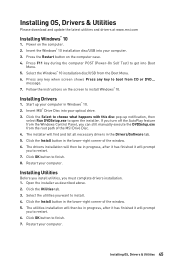
Insert the Windows® 10 installation disc/USB into Boot Menu. 5. Press F11 key during the computer POST (Power-On Self Test) to restart. 7. Press any key when screen shows Press any key to finish. 8. If you turn off the AutoPlay feature from the Windows Control Panel, you can still manually execute the DVDSetup.exe from the root path of the window. 6. Open the installer as described above. 2. Restart...
Insert the Windows® 10 installation disc/USB into Boot Menu. 5. Press F11 key during the computer POST (Power-On Self Test) to restart. 7. Press any key when screen shows Press any key to finish. 8. If you turn off the AutoPlay feature from the Windows Control Panel, you can still manually execute the DVDSetup.exe from the root path of the window. 6. Open the installer as described above. 2. Restart...
User Manual
Page 48
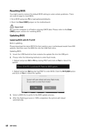
... methods to enter flash mode. ▪▪Reboot and press Ctrl + F5 key during POST to perform the BIOS update process. 4. Updating BIOS Updating BIOS with M-FLASH Before updating: Please download the latest BIOS file that contains the update file into the USB flash drive. Click the M-FLASH button and click on Yes to reboot the system. And then save the BIOS file into the USB port. 2. Updating BIOS: 1. Please refer to load optimized defaults. ∙∙Short the Clear CMOS jumper on the motherboard. ⚠...
... methods to enter flash mode. ▪▪Reboot and press Ctrl + F5 key during POST to perform the BIOS update process. 4. Updating BIOS Updating BIOS with M-FLASH Before updating: Please download the latest BIOS file that contains the update file into the USB flash drive. Click the M-FLASH button and click on Yes to reboot the system. And then save the BIOS file into the USB port. 2. Updating BIOS: 1. Please refer to load optimized defaults. ∙∙Short the Clear CMOS jumper on the motherboard. ⚠...
User Manual
Page 51
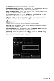
... the CPU, Memory, Storage, Fan Info and Help buttons to right. ∙∙ Component Information - The boot priority from high to low is enabled when the button shows ON . ⚠⚠Important The function buttons will vary with a USB flash drive. ∙∙ Hardware Monitor - The function is left to show the Favorites window. allows you to manually control the fan speed by clicking on this button to enter the Hardware Monitor menu...
... the CPU, Memory, Storage, Fan Info and Help buttons to right. ∙∙ Component Information - The boot priority from high to low is enabled when the button shows ON . ⚠⚠Important The function buttons will vary with a USB flash drive. ∙∙ Hardware Monitor - The function is left to show the Favorites window. allows you to manually control the fan speed by clicking on this button to enter the Hardware Monitor menu...
User Manual
Page 53
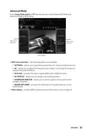
... be configured. UEFI BIOS 53 allows you to manage overclocking profiles. ▪▪HARDWARE MONITOR - provides BIOS setting items and information to update BIOS with a USB flash drive. ▪▪OC PROFILE - provides the information of system. ▪▪BOARD EXPLORER - allows you to set the speeds of fans and monitor voltages of installed devices on this motherboard. ∙∙ Menu display - BIOS menu selection BIOS menu selection Menu display ∙∙ BIOS menu selection - allows you to adjust the frequency and voltage...
... be configured. UEFI BIOS 53 allows you to manage overclocking profiles. ▪▪HARDWARE MONITOR - provides BIOS setting items and information to update BIOS with a USB flash drive. ▪▪OC PROFILE - provides the information of system. ▪▪BOARD EXPLORER - allows you to set the speeds of fans and monitor voltages of installed devices on this motherboard. ∙∙ Menu display - BIOS menu selection BIOS menu selection Menu display ∙∙ BIOS menu selection - allows you to adjust the frequency and voltage...
User Manual
Page 54
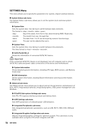
... connected SATA/ M.2 device. ⚠⚠Important If the connected SATA/ M.2 device is not displayed, turn off computer and re-check SATA/ M.2 cable and power cable connections of onboard power LED behaviors. ▶▶Integrated Peripherals sub-menu Sets integrated peripherals' parameters, such as LAN, Wi-Fi, HDD, SSD, USB and audio. ▶▶Integrated Graphics Configuration sub-menu Adjusts integrated graphics settings for system, chipset and boot devices. ▶▶System Status sub-menu The System Status sub-menu allows you to switch...
... connected SATA/ M.2 device. ⚠⚠Important If the connected SATA/ M.2 device is not displayed, turn off computer and re-check SATA/ M.2 cable and power cable connections of onboard power LED behaviors. ▶▶Integrated Peripherals sub-menu Sets integrated peripherals' parameters, such as LAN, Wi-Fi, HDD, SSD, USB and audio. ▶▶Integrated Graphics Configuration sub-menu Adjusts integrated graphics settings for system, chipset and boot devices. ▶▶System Status sub-menu The System Status sub-menu allows you to switch...
User Manual
Page 55
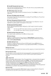
... in this menu to load the BIOS default values or factory default settings into the BIOS and exit the BIOS setup utility with or without changes. This function is being disabled. You may also press Esc key to enter the sub-menu. ▶▶Super IO Configuration sub-menu Sets system Super I/O chip parameters including LPT and COM ports. Once the password is the best way to enter a new password. Press Enter to abort...
... in this menu to load the BIOS default values or factory default settings into the BIOS and exit the BIOS setup utility with or without changes. This function is being disabled. You may also press Esc key to enter the sub-menu. ▶▶Super IO Configuration sub-menu Sets system Super I/O chip parameters including LPT and COM ports. Once the password is the best way to enter a new password. Press Enter to abort...
User Manual
Page 56
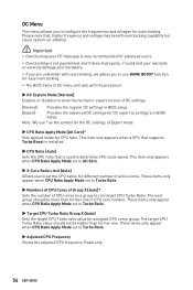
... use * as a group to configure the frequencies and voltages for assigned CPU cores group. This item only appears when a CPU that supports Turbo Boost is installed. ▶▶CPU Ratio [Auto] Sets the CPU ratio that , higher frequency and voltage may benefit overclocking capability but cause system un-stability. ⚠⚠Important ∙∙Overclocking your PC manually is only recommended for advanced users. ∙∙Overclocking is used to configure in BIOS setup...
... use * as a group to configure the frequencies and voltages for assigned CPU cores group. This item only appears when a CPU that supports Turbo Boost is installed. ▶▶CPU Ratio [Auto] Sets the CPU ratio that , higher frequency and voltage may benefit overclocking capability but cause system un-stability. ⚠⚠Important ∙∙Overclocking your PC manually is only recommended for advanced users. ∙∙Overclocking is used to configure in BIOS setup...
User Manual
Page 57
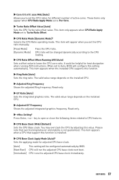
... CPU by BIOS. [Next Boot] CPU will configure this value. This item appears when a CPU that overclocking behavior and stability is installed. ▶▶CPU Base Clock Apply Mode [Auto]* Sets the applying mode for adjusted CPU base clock. [Auto] This setting will appear when you to Per Core. ▶▶Turbo Ratio Offset Value [Auto] Sets the CPU Turbo ratio offset value. When set to CPU features. ▶▶CPU Base Clock (MHz) [Default] Sets the CPU Base clock. key...
... CPU by BIOS. [Next Boot] CPU will configure this value. This item appears when a CPU that overclocking behavior and stability is installed. ▶▶CPU Base Clock Apply Mode [Auto]* Sets the applying mode for adjusted CPU base clock. [Auto] This setting will appear when you to Per Core. ▶▶Turbo Ratio Offset Value [Auto] Sets the CPU Turbo ratio offset value. When set to CPU features. ▶▶CPU Base Clock (MHz) [Default] Sets the CPU Base clock. key...
User Manual
Page 58
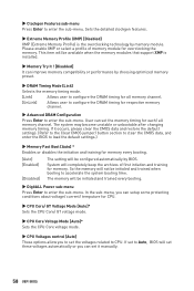
... CPU Core voltage mode. ▶▶CPU Voltages control [Auto] These options allow you can improve memory compatibility or performance by BIOS. This item will be initialed and trained when booting to configure the DRAM timing for overclocking the memory. Sets the detailed clockgen features. ▶▶Extreme Memory Profile (XMP) [Disabled] XMP (Extreme Memory Profile) is installed. ▶▶Memory Try It ! [Disabled] It can set it occurs, please clear the CMOS data and restore the default settings...
... CPU Core voltage mode. ▶▶CPU Voltages control [Auto] These options allow you can improve memory compatibility or performance by BIOS. This item will be initialed and trained when booting to configure the DRAM timing for overclocking the memory. Sets the detailed clockgen features. ▶▶Extreme Memory Profile (XMP) [Disabled] XMP (Extreme Memory Profile) is installed. ▶▶Memory Try It ! [Disabled] It can set it occurs, please clear the CMOS data and restore the default settings...
User Manual
Page 59
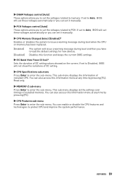
... load the default settings for new devices. ▶▶DRAM Voltages control [Auto] These options allow you to set the voltages related to memory. Read only. ▶▶MEMORY-Z sub-menu Press Enter to PCH. UEFI BIOS 59 If set to Auto, BIOS will set these voltages automatically or you can set it manually. ▶▶CPU Memory Changed Detect [Enabled]* Enables or disables the system to issue a warning message during boot when the CPU or memory has been replaced. [Enabled] [Disabled] The system will set these voltages...
... load the default settings for new devices. ▶▶DRAM Voltages control [Auto] These options allow you to set the voltages related to memory. Read only. ▶▶MEMORY-Z sub-menu Press Enter to PCH. UEFI BIOS 59 If set to Auto, BIOS will set these voltages automatically or you can set it manually. ▶▶CPU Memory Changed Detect [Enabled]* Enables or disables the system to issue a warning message during boot when the CPU or memory has been replaced. [Enabled] [Disabled] The system will set these voltages...
User Manual
Page 60
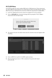
... USB flash drive that matches your motherboard model from MSI website, save the BIOS file into the computer. 2. Click on M-FLASH tab, a demand message will appear after rebooting. 4. M-FLASH Menu M-FLASH provides the way to reboot and enter the flash mode. 3. The system will enter the flash mode and a file selection menu will be prompted. After the flashing process is 100% completed, the system will reboot automatically. 60 UEFI BIOS Select a BIOS file to update BIOS. 1. Please download...
... USB flash drive that matches your motherboard model from MSI website, save the BIOS file into the computer. 2. Click on M-FLASH tab, a demand message will appear after rebooting. 4. M-FLASH Menu M-FLASH provides the way to reboot and enter the flash mode. 3. The system will enter the flash mode and a file selection menu will be prompted. After the flashing process is 100% completed, the system will reboot automatically. 60 UEFI BIOS Select a BIOS file to update BIOS. 1. Please download...

User Manual
Page 69
... RAID Drivers USB flash drive. Insert the MSI Drive Disk into the optical drive. 3. Installing Intel® Rapid Storage Technology Software 1. exe from the Windows Control Panel, you to restart, click OK button to install a third party RAID driver. 2. Restart your computer and enter the Windows operating system. 8. Select the (iaStorAC.inf) driver, click Next. 5. Windows setup will need to copy the files after selecting the location to install Windows click on Load driver button to finish. 7. Click the Install button. 6. RAID Configuration 69 If you turn...
... RAID Drivers USB flash drive. Insert the MSI Drive Disk into the optical drive. 3. Installing Intel® Rapid Storage Technology Software 1. exe from the Windows Control Panel, you to restart, click OK button to install a third party RAID driver. 2. Restart your computer and enter the Windows operating system. 8. Select the (iaStorAC.inf) driver, click Next. 5. Windows setup will need to copy the files after selecting the location to install Windows click on Load driver button to finish. 7. Click the Install button. 6. RAID Configuration 69 If you turn...
User Manual
Page 70
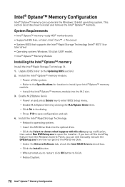
... 64 bit (UEFI mode). ∙∙Intel® Optane™ Memory Module Installing the Intel® Optane™ memory Install the Intel® Rapid Storage Technology 16. 1. Update BIOS (refer to the Updating BIOS section). 2. Intel® Optane™ Memory Configuration Intel® Optane™ memory can still manually execute the DVDSetup.exe from the root path of the MSI Drive Disk. ▫▫Under the Drivers/Software tab, check the Intel RAID Drivers...
... 64 bit (UEFI mode). ∙∙Intel® Optane™ Memory Module Installing the Intel® Optane™ memory Install the Intel® Rapid Storage Technology 16. 1. Update BIOS (refer to the Updating BIOS section). 2. Intel® Optane™ Memory Configuration Intel® Optane™ memory can still manually execute the DVDSetup.exe from the root path of the MSI Drive Disk. ▫▫Under the Drivers/Software tab, check the Intel RAID Drivers...
User Manual
Page 73
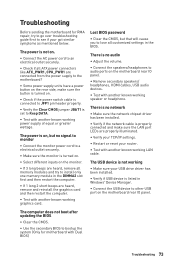
...;If 1 long 2 short beeps are properly illuminated. ∙∙Verify your TCP/IP settings. ∙∙Restart or reset your USB drive driver has been installed. ∙∙Verify if USB device is on . ∙∙Check if the power switch cable is connected to JFP1 pin header properly. ∙∙Verify the Clear CMOS jumper JBAT1 is properly connected and make sure the LAN port LEDs are heard, remove and reinstall the graphics card and then...
...;If 1 long 2 short beeps are properly illuminated. ∙∙Verify your TCP/IP settings. ∙∙Restart or reset your USB drive driver has been installed. ∙∙Verify if USB device is on . ∙∙Check if the power switch cable is connected to JFP1 pin header properly. ∙∙Verify the Clear CMOS jumper JBAT1 is properly connected and make sure the LAN port LEDs are heard, remove and reinstall the graphics card and then...
User Manual
Page 77
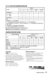
... Int'l Co.,Ltd. Technical Support If a problem arises with your place of purchase or local distributor. No warranty as to this document without prior notice. Version 1.2, 2020/10, updated release. Alternatively, please try the following help resources for technical guide, BIOS updates, driver updates, and other marks and names mentioned may be obtained from the user guide, please contact your system...
... Int'l Co.,Ltd. Technical Support If a problem arises with your place of purchase or local distributor. No warranty as to this document without prior notice. Version 1.2, 2020/10, updated release. Alternatively, please try the following help resources for technical guide, BIOS updates, driver updates, and other marks and names mentioned may be obtained from the user guide, please contact your system...


