User Guide
Page 1
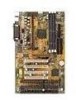
... LM78 function includes: CPU /power supply/chassis fan revolution detect, CPU/system voltage monitor, system temperature monitor, and chassis intrusion detect(optional). The Pentium® II processor supports MMXTM (Multimedia Extension) technology. The Intel® 82371EB chipset also improves the IDE transfer rate by supporting Ultra DMA/33 IDE that transfers data at the rate of 33MB/s. Specification & User's Guide MMIICCRROO--SSTTAARR IINNTTEERRNNAATTIIOONNAALL COMPANY LTD. Introduction The MSI ATX BX2 mainboard is a high-performance personal computer...
... LM78 function includes: CPU /power supply/chassis fan revolution detect, CPU/system voltage monitor, system temperature monitor, and chassis intrusion detect(optional). The Pentium® II processor supports MMXTM (Multimedia Extension) technology. The Intel® 82371EB chipset also improves the IDE transfer rate by supporting Ultra DMA/33 IDE that transfers data at the rate of 33MB/s. Specification & User's Guide MMIICCRROO--SSTTAARR IINNTTEERRNNAATTIIOONNAALL COMPANY LTD. Introduction The MSI ATX BX2 mainboard is a high-performance personal computer...
User Guide
Page 3
... used as ISA or PCI. Switching Voltage Regulator l On-board switching mode DC-DC Step Down Regulator. l Supports ECC(1-bit Error Code Correct) and EC(Multiple-Bit Error Checking) function. AGP specification compliant - l Can connect up to Intel® VRM ver 8.2 specifications. Mainboard Specification FEATURES SPECIFICATIONS CPU l Slot 1 for Pentium® II Processor . l Supports 3.3v SDRAM DIMM. l An IDE controller on the Intel® 82371EB PCI Chipset provides IDE HDD/CD-ROM with PIO, Bus Master and Ultra DMA/33 operation modes. l Core/Bus...
... used as ISA or PCI. Switching Voltage Regulator l On-board switching mode DC-DC Step Down Regulator. l Supports ECC(1-bit Error Code Correct) and EC(Multiple-Bit Error Checking) function. AGP specification compliant - l Can connect up to Intel® VRM ver 8.2 specifications. Mainboard Specification FEATURES SPECIFICATIONS CPU l Slot 1 for Pentium® II Processor . l Supports 3.3v SDRAM DIMM. l An IDE controller on the Intel® 82371EB PCI Chipset provides IDE HDD/CD-ROM with PIO, Bus Master and Ultra DMA/33 operation modes. l Core/Bus...
User Guide
Page 4
... cards of the board automatically. l ATX Form Factor: 30cm(L) x 18.6cm(W) x 4 layers PCB. MICRO-STAR INTERNATIONAL COMPANY LTD. l CPU/Power Supply/Chassis Fan Revolution Detect l CPU Fan Control (the fan will automatically stop when the system enters suspend mode) l System Voltage Detect l CPU Overheat Warning (reserved) l Chassis Intrusion Detect(reserved) l Display Actual Current Voltage l PIIX4(82371EB) built-in RTC. l Double deck Serial & LPT port. Specification & User's Guide FEATURES On-Board Peripherals BIOS On-Board System Hardware Monitor(LM78) RTC Keyboard Connector...
... cards of the board automatically. l ATX Form Factor: 30cm(L) x 18.6cm(W) x 4 layers PCB. MICRO-STAR INTERNATIONAL COMPANY LTD. l CPU/Power Supply/Chassis Fan Revolution Detect l CPU Fan Control (the fan will automatically stop when the system enters suspend mode) l System Voltage Detect l CPU Overheat Warning (reserved) l Chassis Intrusion Detect(reserved) l Display Actual Current Voltage l PIIX4(82371EB) built-in RTC. l Double deck Serial & LPT port. Specification & User's Guide FEATURES On-Board Peripherals BIOS On-Board System Hardware Monitor(LM78) RTC Keyboard Connector...
User Guide
Page 10
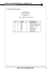
Specification & User's Guide 4.1-5 Serial Port Connectors 1 2 3 4 5 6 7 8 9 COM A / COMB 9-Pin male DIN connectors PIN SIGNAL 1 DCD 2 SIN 3 SOUT 4 DTR 5 GND 6 DSR 7 RTS 8 CTS 9 RI DESCRIPTION Data Carry Detect Serial In or Receive Data Serial Out or Transmit Data Data Terminal Ready) Ground Data Set Ready Request To Send Clear To Send Ring Indicate MS-6119 ATX BX2 Mainboard 10 MICRO-STAR INTERNATIONAL COMPANY LTD.
Specification & User's Guide 4.1-5 Serial Port Connectors 1 2 3 4 5 6 7 8 9 COM A / COMB 9-Pin male DIN connectors PIN SIGNAL 1 DCD 2 SIN 3 SOUT 4 DTR 5 GND 6 DSR 7 RTS 8 CTS 9 RI DESCRIPTION Data Carry Detect Serial In or Receive Data Serial Out or Transmit Data Data Terminal Ready) Ground Data Set Ready Request To Send Clear To Send Ring Indicate MS-6119 ATX BX2 Mainboard 10 MICRO-STAR INTERNATIONAL COMPANY LTD.
User Guide
Page 12
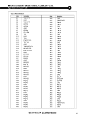
Specification & User's Guide Slot 1 Pin Definition PIN SIGNAL A1 VCC_VTT A2 GND A3 VCC_VTT A4 IERR# A5 A20M# A6 GND A7 FERR# A8 IGNNE...] A36 D#[53] A37 D#[57] A38 GND A39 D#[46] A40 D#[49] A41 D#[51] A42 GND A43 D#[42] A44 D#[45] A45 D#[39] PIN SIGNAL A46 GND A47 RESERVED A48 D#[43] A49 D#[37] A50 GND A51 D#[33] A52 D#[36] A53 D#[31] A54 GND A55 D#[30] A56 D#[27...GND A83 A#[31] A84 A#[27] A85 A#[22] A86 GND A87 A#[23] A88 RESERVED A89 A#[19] A90 GND MS-6119 ATX BX2 Mainboard 12 MICRO-STAR INTERNATIONAL COMPANY LTD.
Specification & User's Guide Slot 1 Pin Definition PIN SIGNAL A1 VCC_VTT A2 GND A3 VCC_VTT A4 IERR# A5 A20M# A6 GND A7 FERR# A8 IGNNE...] A36 D#[53] A37 D#[57] A38 GND A39 D#[46] A40 D#[49] A41 D#[51] A42 GND A43 D#[42] A44 D#[45] A45 D#[39] PIN SIGNAL A46 GND A47 RESERVED A48 D#[43] A49 D#[37] A50 GND A51 D#[33] A52 D#[36] A53 D#[31] A54 GND A55 D#[30] A56 D#[27...GND A83 A#[31] A84 A#[27] A85 A#[22] A86 GND A87 A#[23] A88 RESERVED A89 A#[19] A90 GND MS-6119 ATX BX2 Mainboard 12 MICRO-STAR INTERNATIONAL COMPANY LTD.
User Guide
Page 13
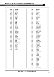
Specification & User's Guide PIN A91 A92 A93 A94 A95 A96 A97 A98 A99 A100 A101 A102 A103 A104 A105 A106 A107 A108 ... A#[9] A#[4] BNR# GND BPRI# TRDY# DEFER# GND REQ#[2] REQ#[3] HITM# GND DBSY# RS#[1] RESERVED GND ADS# RESERVED AP#[0] GND VID[2] VID[1] VID[4] PIN SIGNAL B1 EMI B2 FLUSH# B3 SMI# B4 INIT# B5 VCC_VTT B6 STPCLK# B7 TCK B8 SLP# B9 VCC_VTT B10 TMS B11 TRST# B12 RESERVED...54} B37 VCC_CORE B38 D#[59] B39 D#[48] B40 D#[52] B41 EMI B42 D#[41] B43 D#[47] B44 D#[44] B45 VCC_CORE MS-6119 ATX BX2 Mainboard 13 MICRO-STAR INTERNATIONAL COMPANY LTD.
Specification & User's Guide PIN A91 A92 A93 A94 A95 A96 A97 A98 A99 A100 A101 A102 A103 A104 A105 A106 A107 A108 ... A#[9] A#[4] BNR# GND BPRI# TRDY# DEFER# GND REQ#[2] REQ#[3] HITM# GND DBSY# RS#[1] RESERVED GND ADS# RESERVED AP#[0] GND VID[2] VID[1] VID[4] PIN SIGNAL B1 EMI B2 FLUSH# B3 SMI# B4 INIT# B5 VCC_VTT B6 STPCLK# B7 TCK B8 SLP# B9 VCC_VTT B10 TMS B11 TRST# B12 RESERVED...54} B37 VCC_CORE B38 D#[59] B39 D#[48] B40 D#[52] B41 EMI B42 D#[41] B43 D#[47] B44 D#[44] B45 VCC_CORE MS-6119 ATX BX2 Mainboard 13 MICRO-STAR INTERNATIONAL COMPANY LTD.
User Guide
Page 15
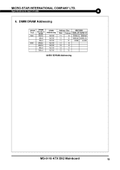
Side(S) pcs. DIMM DRAM Addressing DRAM Tech. 16M 64M DRAM Density & Width 1Mx16 2Mx8 4Mx4 2Mx32 4Mx16 8Mx8 16Mx4 DRAM Addressing ASYM ASYM ASYM ASYM ASYM ASYM ASYM Address Size Row Column 11 8 MB/DIMM Single no . Double no . MICRO-STAR INTERNATIONAL COMPANY LTD. Specification & User's Guide 6. Side(D) pcs. 8MBx4 16MBx8 11 9 16MBx8 32MBx16 11 10 32MB 64MB 11 8 12 8 12 9 12 10 440BX SDRAM Addressing MS-6119 ATX BX2 Mainboard 15
Side(S) pcs. DIMM DRAM Addressing DRAM Tech. 16M 64M DRAM Density & Width 1Mx16 2Mx8 4Mx4 2Mx32 4Mx16 8Mx8 16Mx4 DRAM Addressing ASYM ASYM ASYM ASYM ASYM ASYM ASYM Address Size Row Column 11 8 MB/DIMM Single no . Double no . MICRO-STAR INTERNATIONAL COMPANY LTD. Specification & User's Guide 6. Side(D) pcs. 8MBx4 16MBx8 11 9 16MBx8 32MBx16 11 10 32MB 64MB 11 8 12 8 12 9 12 10 440BX SDRAM Addressing MS-6119 ATX BX2 Mainboard 15
User Guide
Page 17
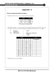
... Clock Frequency multiplied by the Core/Bus ratio. The actual core speed of the CPU is used to set the clock at 33MHz. Specification & User's Guide Appendix A CPU Core Speed Derivation Procedure 1. For it will adjust itself to set the Core/Bus (Fraction) ratio of the CPU. The DIP Switch SW1 (4 & 5) is fixed at 100MHZ. The PCI Bus Clock is used to adjust the CPU clock frequency. For example: If CPU Clock Core/Bus ratio then CPU core speed = 66MHz = 1.5 = Host Clock x Core/Bus ratio = 66MHz x 1.5 = 100MHz SW1 CPU 1 2 3 4 Core/Bus...
... Clock Frequency multiplied by the Core/Bus ratio. The actual core speed of the CPU is used to set the clock at 33MHz. Specification & User's Guide Appendix A CPU Core Speed Derivation Procedure 1. For it will adjust itself to set the Core/Bus (Fraction) ratio of the CPU. The DIP Switch SW1 (4 & 5) is fixed at 100MHZ. The PCI Bus Clock is used to adjust the CPU clock frequency. For example: If CPU Clock Core/Bus ratio then CPU core speed = 66MHz = 1.5 = Host Clock x Core/Bus ratio = 66MHz x 1.5 = 100MHz SW1 CPU 1 2 3 4 Core/Bus...
User Guide
Page 18
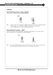
Specification & User's Guide Jumpers Flash ROM Programming Voltage: JMODE1 This jumper is for normal operation. External Battery Connector: JBAT1 A battery must short 1-2 pins of the Flash ROM BIOS. Then, return to retain the mainboard configuration in CMOS RAM. Leave JMODE1 open, if you 're using Intel® or MXIC flash memory for setting the voltage of JBAT1 to flash the ROM data. JMODE1 +12V 1 PWD VCC 3 +12V 1 PWD VCC 3 Note: +12V +5V (default) a. b. If you use the on ; Avoid clearing the...
Specification & User's Guide Jumpers Flash ROM Programming Voltage: JMODE1 This jumper is for normal operation. External Battery Connector: JBAT1 A battery must short 1-2 pins of the Flash ROM BIOS. Then, return to retain the mainboard configuration in CMOS RAM. Leave JMODE1 open, if you 're using Intel® or MXIC flash memory for setting the voltage of JBAT1 to flash the ROM data. JMODE1 +12V 1 PWD VCC 3 +12V 1 PWD VCC 3 Note: +12V +5V (default) a. b. If you use the on ; Avoid clearing the...
User Guide
Page 19
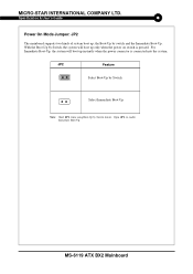
... ATX BX2 Mainboard Open JP2, to enable Immediate Boot-Up. Specification & User's Guide Power On Mode Jumper: JP2 The mainboard supports two kinds of system boot up: the Boot-Up by Switch feature. For Immediate Boot-Up, the system will boot up instantly when the power connector is pressed. JP2 Feature Select Boot-Up by Swtich Select Immediate Boot-Up Note: Short JP2, when using Boot-Up by switch and the Immediate Boot-Up. With the Boot...
... ATX BX2 Mainboard Open JP2, to enable Immediate Boot-Up. Specification & User's Guide Power On Mode Jumper: JP2 The mainboard supports two kinds of system boot up: the Boot-Up by Switch feature. For Immediate Boot-Up, the system will boot up instantly when the power connector is pressed. JP2 Feature Select Boot-Up by Swtich Select Immediate Boot-Up Note: Short JP2, when using Boot-Up by switch and the Immediate Boot-Up. With the Boot...
User Guide
Page 20
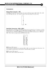
...jumper accordingly. IDE1 can also connect a Master and a Slave drive. MICRO-STAR INTERNATIONAL COMPANY LTD. You must configure second hard drive to IDE1. This connector supports the provided floppy drive ribbon cable. Specification & User's Guide Connectors Floppy Disk Connector: FDC The mainboard also provides a standard floppy disk connector FDC that provides PIO mode 0~4, Bus Master, and Ultra DMA/33 function. These connectors support the provided IDE hard disk cable. You can connect up to four hard disk drives, CD-ROM, 120MB Floppy (reserved for future BIOS) and other devices...
...jumper accordingly. IDE1 can also connect a Master and a Slave drive. MICRO-STAR INTERNATIONAL COMPANY LTD. You must configure second hard drive to IDE1. This connector supports the provided floppy drive ribbon cable. Specification & User's Guide Connectors Floppy Disk Connector: FDC The mainboard also provides a standard floppy disk connector FDC that provides PIO mode 0~4, Bus Master, and Ultra DMA/33 function. These connectors support the provided IDE hard disk cable. You can connect up to four hard disk drives, CD-ROM, 120MB Floppy (reserved for future BIOS) and other devices...
User Guide
Page 21
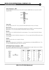
... than turning the power ON/OFF. Power LED The Power LED is always lit while the system power is used to this pin. ATX 20-pin Power Connector: JWR1 This connector supports the power button on . Avoid rebooting while the HDD LED is lit. You can connect the Power LED from the system case is always ON. HDD LED HDD LED shows the activity of a hard disk drive. You can connect the keylock to this pin. Specification & User's Guide Case Connector: JFP1 The Turbo LED, Reset Switch, Keylock, Power LED, Speaker and HDD LED are supported...
... than turning the power ON/OFF. Power LED The Power LED is always lit while the system power is used to this pin. ATX 20-pin Power Connector: JWR1 This connector supports the power button on . Avoid rebooting while the HDD LED is lit. You can connect the Power LED from the system case is always ON. HDD LED HDD LED shows the activity of a hard disk drive. You can connect the keylock to this pin. Specification & User's Guide Case Connector: JFP1 The Turbo LED, Reset Switch, Keylock, Power LED, Speaker and HDD LED are supported...
User Guide
Page 22
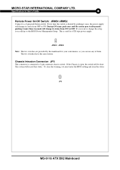
... 2-pin connector chassis switch. Chassis Intrusion Connector: JP3 This connector is used for your convenience, so you must enter the BIOS settting and clear the status. During ON stage, push once and the system goes to sleep mode: pushing it once, the power supply will change its status from ON to a 2-pin push button switch. JP3 MS-6119 ATX BX2 Mainboard The system will be short. Specification & User's Guide Remote Power On/Off Switch: JRMS1/JRMS2 Connect to...
... 2-pin connector chassis switch. Chassis Intrusion Connector: JP3 This connector is used for your convenience, so you must enter the BIOS settting and clear the status. During ON stage, push once and the system goes to sleep mode: pushing it once, the power supply will change its status from ON to a 2-pin push button switch. JP3 MS-6119 ATX BX2 Mainboard The system will be short. Specification & User's Guide Remote Power On/Off Switch: JRMS1/JRMS2 Connect to...
User Guide
Page 23
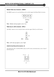
.... Specification & User's Guide Modem Wake Up Connector: JMDM1 The JMDM1 connector is active "low". Wake-Up on LAN connector: JWOL1 The JWOL1 connector is active "high". NC GND NC 5VSB MDM_WAKEUP JMDM1 Note: Modem wake-up signal is for use with this feature, such as Creative® PCI 3D sound card. DMA Grand Signal 1 GND 3 4 6 Seried IRQ DMA Request Signal J3 MS-6119 ATX BX2 Mainboard MICRO-STAR INTERNATIONAL COMPANY...
.... Specification & User's Guide Modem Wake Up Connector: JMDM1 The JMDM1 connector is active "low". Wake-Up on LAN connector: JWOL1 The JWOL1 connector is active "high". NC GND NC 5VSB MDM_WAKEUP JMDM1 Note: Modem wake-up signal is for use with this feature, such as Creative® PCI 3D sound card. DMA Grand Signal 1 GND 3 4 6 Seried IRQ DMA Request Signal J3 MS-6119 ATX BX2 Mainboard MICRO-STAR INTERNATIONAL COMPANY...

User Guide
Page 27
Bill for Materials MS-6119 ATX BX2 Mainboard Specification & User's Guide Appendix C - MICRO-STAR INTERNATIONAL COMPANY LTD.
Bill for Materials MS-6119 ATX BX2 Mainboard Specification & User's Guide Appendix C - MICRO-STAR INTERNATIONAL COMPANY LTD.
User Guide
Page 32
... preparation of this document is given as to make changes without notice. Shanghai, P.R.C. Our products are under continual improvement and we reserve the right to the correctness of MICRO-STAR INTERNATIONAL. Specification & User's Guide MAIN OFFICE MICRO-STAR INTERNATIONAL No. 69, Li-De St., Jung-He City...guarantee is the intellectual property of its contents. MICRO-STAR INTERNATIONAL COMPANY LTD. MS-6119 ATX BX2 Mainboard Tel: 1-510-623-8818 Fax: 1-510-623-8585 BBS: 1-510-623-7398 http:// www.achme.com MSI COMPUTER GMBH (GERMANY) Waldstrasse 23 63128 Dietzenbach 2, Germany Tel...
... preparation of this document is given as to make changes without notice. Shanghai, P.R.C. Our products are under continual improvement and we reserve the right to the correctness of MICRO-STAR INTERNATIONAL. Specification & User's Guide MAIN OFFICE MICRO-STAR INTERNATIONAL No. 69, Li-De St., Jung-He City...guarantee is the intellectual property of its contents. MICRO-STAR INTERNATIONAL COMPANY LTD. MS-6119 ATX BX2 Mainboard Tel: 1-510-623-8818 Fax: 1-510-623-8585 BBS: 1-510-623-7398 http:// www.achme.com MSI COMPUTER GMBH (GERMANY) Waldstrasse 23 63128 Dietzenbach 2, Germany Tel...

