
User Guide
Page 8
... (Waste Electrical and Electronic Equipment) Statement v Chapter 1 Getting Started 1-1 Mainboard Specifications 1-2 Mainboard Layout 1-4 Packing Checklist 1-5 Chapter 2 Hardware Setup 2-1 Quick Components Guide 2-2 CPU (Central Processing Unit 2-3 Memory 2-6 Power Supply 2-8 Back Panel 2-9 Connectors 2-11 Switch 2-17 Jumpers 2-18 Button 2-19 Slots 2-20 LED Status Indicators 2-24 Chapter 3 BIOS Setup 3-1 Entering Setup 3-2 The Main...
... (Waste Electrical and Electronic Equipment) Statement v Chapter 1 Getting Started 1-1 Mainboard Specifications 1-2 Mainboard Layout 1-4 Packing Checklist 1-5 Chapter 2 Hardware Setup 2-1 Quick Components Guide 2-2 CPU (Central Processing Unit 2-3 Memory 2-6 Power Supply 2-8 Back Panel 2-9 Connectors 2-11 Switch 2-17 Jumpers 2-18 Button 2-19 Slots 2-20 LED Status Indicators 2-24 Chapter 3 BIOS Setup 3-1 Entering Setup 3-2 The Main...

User Guide
Page 12
... ■ NVIDIA® nForce 750a SLI single chipset Memory Support ■ DDR3 800/ 1066/ 1333/ 1600 (OC) SDRAM (16GB Max) ■ 4 DDR3 DIMMs (240pin/ 1.5V) (For more information on compatible components, please visit http://www.msi.com/index.php?func=testreport) Integrated Graphic ■ ...Integrated Geforce 8200 GPU (for NVIDIA® nForce 750a SLI Chipset) ■ Share Memory: up to 512MB LAN ■ Supports LAN 10/100/1000 Fast Ethernet...
... ■ NVIDIA® nForce 750a SLI single chipset Memory Support ■ DDR3 800/ 1066/ 1333/ 1600 (OC) SDRAM (16GB Max) ■ 4 DDR3 DIMMs (240pin/ 1.5V) (For more information on compatible components, please visit http://www.msi.com/index.php?func=testreport) Integrated Graphic ■ ...Integrated Geforce 8200 GPU (for NVIDIA® nForce 750a SLI Chipset) ■ Share Memory: up to 512MB LAN ■ Supports LAN 10/100/1000 Fast Ethernet...
User Guide
Page 22
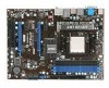
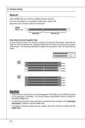
... are used for Dual-Channel mode. The following illustrations explain the population rules for installing memory modules. For more information on compatible components, please visit http://www.msi.com/index.php?func=testreport DDR3 240-pin, 1.5V 48x2=96 pin 72x2=144 pin Dual-Channel mode ...Population Rule In Dual-Channel mode, the memory modules can enhance the system performance. You should always install DDR3 memory modules in the DDR3 DIMM...
... are used for Dual-Channel mode. The following illustrations explain the population rules for installing memory modules. For more information on compatible components, please visit http://www.msi.com/index.php?func=testreport DDR3 240-pin, 1.5V 48x2=96 pin 72x2=144 pin Dual-Channel mode ...Population Rule In Dual-Channel mode, the memory modules can enhance the system performance. You should always install DDR3 memory modules in the DDR3 DIMM...

User Guide
Page 23
...the DIMM slot. Then push it in until the golden finger on the center and will automatically close when the memory module is properly seated. 3. The memory module has only one notch on the memory module is properly inserted in the right orientation. 2. Important You can barely see the golden finger if the... memory module is deeply inserted in place by the DIMM slot clips at each side of the DIMM slot will only fit in the DIMM slot. MS-7578 Installing Memory Modules 1. Manually check if the memory module has been locked in the DIMM slot...
...the DIMM slot. Then push it in until the golden finger on the center and will automatically close when the memory module is properly seated. 3. The memory module has only one notch on the memory module is properly inserted in the right orientation. 2. Important You can barely see the golden finger if the... memory module is deeply inserted in place by the DIMM slot clips at each side of the DIMM slot will only fit in the DIMM slot. MS-7578 Installing Memory Modules 1. Manually check if the memory module has been locked in the DIMM slot...

User Guide
Page 42
... - 8th digit refers to the date this chapter are under continuous update for reference only. • Upon boot-up, the 1st line appearing after the memory count is the BIOS version. V1.0 refers to the BIOS version. 060909 refers to the customer as MS = all standard customers. Therefore, the description may...
... - 8th digit refers to the date this chapter are under continuous update for reference only. • Upon boot-up, the 1st line appearing after the memory count is the BIOS version. V1.0 refers to the BIOS version. 060909 refers to the customer as MS = all standard customers. Therefore, the description may...
User Guide
Page 48
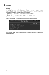
This sub-menu shows the CPU information, BIOS version and memory status of your system (read only). 3-8 ▍ BIOS Setup ▶ Halt On The setting determines whether the system will halt on for 15 seconds and then automatically resume its operation. Available options are: [All Errors] The system stops when any detected error. ▶ System Information Press to enter the sub-menu, and the following screen appears. When the system stops for any error is detected. [No Errors] The system doesn't stop for the errors preset, it will stop if an error is detected at boot.
This sub-menu shows the CPU information, BIOS version and memory status of your system (read only). 3-8 ▍ BIOS Setup ▶ Halt On The setting determines whether the system will halt on for 15 seconds and then automatically resume its operation. Available options are: [All Errors] The system stops when any detected error. ▶ System Information Press to enter the sub-menu, and the following screen appears. When the system stops for any error is detected. [No Errors] The system doesn't stop for the errors preset, it will stop if an error is detected at boot.

User Guide
Page 50
... SLI feature. ▶ On-Chip VGA This setting allows you to enable or disable the on-chip VGA function. ▶ VGA Share Memory Auto This setting controls the exact memory size shared to the VGA card. 3-10 You need to select the MPS version supported by your operating system. ▶ Primary Graphic...
... SLI feature. ▶ On-Chip VGA This setting allows you to enable or disable the on-chip VGA function. ▶ VGA Share Memory Auto This setting controls the exact memory size shared to the VGA card. 3-10 You need to select the MPS version supported by your operating system. ▶ Primary Graphic...

User Guide
Page 54
.... Settings are available only when the BIOS supports S3 sleep mode. ▶ ACPI Function This item is saved to save energy. The information stored in memory will be used to activate the ACPI (Advanced Configuration and Power Management Interface) Function. If your operating system is ACPI-aware, such as Windows 2000... the setting of system configuration and open applications/files is to restore the system when a "wake up" event occurs. 3-14 nents turn off to main memory that remains powered while most other hardware compo- In this field.
.... Settings are available only when the BIOS supports S3 sleep mode. ▶ ACPI Function This item is saved to save energy. The information stored in memory will be used to activate the ACPI (Advanced Configuration and Power Management Interface) Function. If your operating system is ACPI-aware, such as Windows 2000... the setting of system configuration and open applications/files is to restore the system when a "wake up" event occurs. 3-14 nents turn off to main memory that remains powered while most other hardware compo- In this field.
User Guide
Page 58
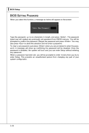
... show up confirming the password will appear on the screen: Type the password, up to confirm the password. This prevents an unauthorized person from CMOS memory. You will boot and you can enter Setup without entering any part of your system configuration. 3-18 Once the password is disabled, the system will...
... show up confirming the password will appear on the screen: Type the password, up to confirm the password. This prevents an unauthorized person from CMOS memory. You will boot and you can enter Setup without entering any part of your system configuration. 3-18 Once the password is disabled, the system will...
User Guide
Page 59
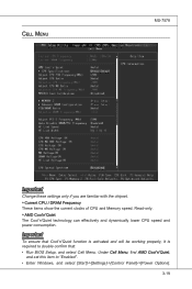
... Change these settings only if you are familiar with the chipset. ▶ Current CPU / DRAM Frequency These items show the current clocks of CPU and Memory speed. Important To ensure that : • Run BIOS Setup, and select Cell Menu. Under Cell Menu, find AMD Cool'n'Quiet, and set this item to...
... Change these settings only if you are familiar with the chipset. ▶ Current CPU / DRAM Frequency These items show the current clocks of CPU and Memory speed. Important To ensure that : • Run BIOS Setup, and select Cell Menu. Under Cell Menu, find AMD Cool'n'Quiet, and set this item to...

User Guide
Page 61
It is for overclock. This submenu displays the information of installed memory. ▶ Advance DRAM Configuration Press to enter the sub-menu and the following screen appears. 3-21 Setting to [Enabled] allows you to set the CPU Ratio higher. MS-7578 ▶ NVIDIA Core Calibration This item is available only when the processor supports this function. ▶ Memory-Z Press to enter the sub-menu and the following screen appears. ▶ DIMM1~4 Memory SPD Information Press to enter the sub-menu and the following screen appears.
It is for overclock. This submenu displays the information of installed memory. ▶ Advance DRAM Configuration Press to enter the sub-menu and the following screen appears. 3-21 Setting to [Enabled] allows you to set the CPU Ratio higher. MS-7578 ▶ NVIDIA Core Calibration This item is available only when the processor supports this function. ▶ Memory-Z Press to enter the sub-menu and the following screen appears. ▶ DIMM1~4 Memory SPD Information Press to enter the sub-menu and the following screen appears.

User Guide
Page 62
... to CAS (column address strobe). It specifies the amount of delay (in clock cycles) that data in the write buffers can be written to the memory cells before precharge occurs. ▶ tRRD When the DRAM Timing Mode sets to [DCT 0], [DCT1] or [Both], the field is adjustable. This... or [Both], the field is refreshed, both rows and columns are addressed separately. The row cycle time determines the minimum number of clock cycles a memory row takes to complete a full cycle, from row activation up to the precharging of a valid write operation, before DRAM refresh may be allowed to ...
... to CAS (column address strobe). It specifies the amount of delay (in clock cycles) that data in the write buffers can be written to the memory cells before precharge occurs. ▶ tRRD When the DRAM Timing Mode sets to [DCT 0], [DCT1] or [Both], the field is adjustable. This... or [Both], the field is refreshed, both rows and columns are addressed separately. The row cycle time determines the minimum number of clock cycles a memory row takes to complete a full cycle, from row activation up to the precharging of a valid write operation, before DRAM refresh may be allowed to ...

User Guide
Page 63
... generated by EMI, set the Hyper-Transport Link speed. Setting to [Auto], the system will remove (turn off) clocks from and write to memory cells. ▶ 1T/2T Memory Timing When the DRAM Timing Mode sets to [DCT 0], [DCT1] or [Both], the field is used to adjust the voltage of CPU...extreme values (spikes) of the pulses are used to the same internal bank of FSB/ DRAM. ▶ Adjusted DRAM Frequency (MHz) It shows the adjusted Memory frequency. This field controls the SDRAM command rate. Remember to disable Spread Spectrum if you to set to [Enabled], the system will detect the HT...
... generated by EMI, set the Hyper-Transport Link speed. Setting to [Auto], the system will remove (turn off) clocks from and write to memory cells. ▶ 1T/2T Memory Timing When the DRAM Timing Mode sets to [DCT 0], [DCT1] or [Both], the field is used to adjust the voltage of CPU...extreme values (spikes) of the pulses are used to the same internal bank of FSB/ DRAM. ▶ Adjusted DRAM Frequency (MHz) It shows the adjusted Memory frequency. This field controls the SDRAM command rate. Remember to disable Spread Spectrum if you to set to [Enabled], the system will detect the HT...

User Guide
Page 109
DotNet Frame Work 2.0 B-C-1 DVD-ROM drive for software installation. 3. Operation system: Windows XP or up. 4. Appendix C Overclocking Center Overclocking Center, the most useful and powerful utility that MSI has spent much research and efforts to develop, helps users to monitor or configure the hardware status of MSI Mainboard in windows, such as CPU clock, voltage, fan speed and temperature. Before you install the Overclocking Center, please make sure the system has meet the following requirements: 1. 256MB system memory. 2.
DotNet Frame Work 2.0 B-C-1 DVD-ROM drive for software installation. 3. Operation system: Windows XP or up. 4. Appendix C Overclocking Center Overclocking Center, the most useful and powerful utility that MSI has spent much research and efforts to develop, helps users to monitor or configure the hardware status of MSI Mainboard in windows, such as CPU clock, voltage, fan speed and temperature. Before you install the Overclocking Center, please make sure the system has meet the following requirements: 1. 256MB system memory. 2.


