

User Guide
Page 8
......2-11 Connectors ...2-12 Jumper ...2-19 Button ...2-20 Slots ...2-21 LED Status Indicators 2-23 Chapter 3 BIOS Setup 3-1 Entering Setup ...3-2 The Main Menu ...3-4 Standard CMOS Features 3-6 Advanced BIOS Features 3-9 Integrated Peripherals 3-12 Power Management Setup 3-14 PNP/PCI Configurations 3-17 H/W Monitor ...3-19... Cell Menu ...3-20 Load Fail-Safe/ Optimized Defaults 3-26 BIOS Setting Password 3-27 Appendix A Realtek ALC888/888T Audio A-1 Installation for W indows 2000/XP A-2 Installing the Realtek HD ...
......2-11 Connectors ...2-12 Jumper ...2-19 Button ...2-20 Slots ...2-21 LED Status Indicators 2-23 Chapter 3 BIOS Setup 3-1 Entering Setup ...3-2 The Main Menu ...3-4 Standard CMOS Features 3-6 Advanced BIOS Features 3-9 Integrated Peripherals 3-12 Power Management Setup 3-14 PNP/PCI Configurations 3-17 H/W Monitor ...3-19... Cell Menu ...3-20 Load Fail-Safe/ Optimized Defaults 3-26 BIOS Setting Password 3-27 Appendix A Realtek ALC888/888T Audio A-1 Installation for W indows 2000/XP A-2 Installing the Realtek HD ...
User Guide
Page 9
Hardware Setup A-18 Appendix B Dual Core Center B-1 Activating Dual Core Center B-2 Main ...B-2 DOT (Dynamic OverClocking B-5 Clock ...B-6 Voltage ...B-7 FAN Speed ...B-8 Temperature ...B-9 User Profile ...B-10 Appendix C Intel ICH9R SATA RAID C-1 ICH9R Introduction C-2 BIOS Configuration C-3 Installing Driver ...C-9 Installing Software C-11 RAID Migration Instructions C-15 Degraded RAID Array C-22 ix
Hardware Setup A-18 Appendix B Dual Core Center B-1 Activating Dual Core Center B-2 Main ...B-2 DOT (Dynamic OverClocking B-5 Clock ...B-6 Voltage ...B-7 FAN Speed ...B-8 Temperature ...B-9 User Profile ...B-10 Appendix C Intel ICH9R SATA RAID C-1 ICH9R Introduction C-2 BIOS Configuration C-3 Installing Driver ...C-9 Installing Software C-11 RAID Migration Instructions C-15 Degraded RAID Array C-22 ix
User Guide
Page 20
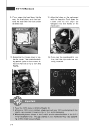
.... locking switch Important 1. Push down the load lever lightly onto the load plate, and then secure the lever with the heatsink. Mainboard photos shown in BIOS (Chapter 3). 2. Then rotate the locking switch (refer to the correct direction marked on it) to avoid damaging. 3. MS-7345 Mainboard 9. Whenever CPU is not installed...
.... locking switch Important 1. Push down the load lever lightly onto the load plate, and then secure the lever with the heatsink. Mainboard photos shown in BIOS (Chapter 3). 2. Then rotate the locking switch (refer to the correct direction marked on it) to avoid damaging. 3. MS-7345 Mainboard 9. Whenever CPU is not installed...
User Guide
Page 28
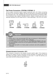
... connectors support system cooling fan with speed sensor to the actual CPU temperature. 3. CINTRU GND 2-14 2 1 JCI1 To clear the warning, you must enter the BIOS utility and clear the record. Fan cooler set with 3 or 4 pins power connector are both available for proper CPU cooling fan. 2. Chassis Intrusion Connector: JCI1...
... connectors support system cooling fan with speed sensor to the actual CPU temperature. 3. CINTRU GND 2-14 2 1 JCI1 To clear the warning, you must enter the BIOS utility and clear the record. Fan cooler set with 3 or 4 pins power connector are both available for proper CPU cooling fan. 2. Chassis Intrusion Connector: JCI1...
User Guide
Page 35
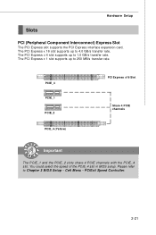
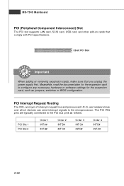
You could select the speed of the PCIE_4 slot in BIOS setup. The PCI Express x 16 slot supports up to 4.0 GB/s transfer rate. Please refer to 250 MB/s transfer rate. The PCI Express x 4 slot supports up ...to 1.0 GB/s transfer rate. PCIEx4 Speed Controller. 2-21 The PCI Express x 1 slot supports up to Chapter 3 BIOS Setup - PCIE_3 PCIE_1 PCIE_2 PCIE_4 (Yellow) PCI Express x16 Slot Share 4 PCIE channels Important The PCIE_1 and the PCIE_2 slots share 4 PCIE channels with the...
You could select the speed of the PCIE_4 slot in BIOS setup. The PCI Express x 16 slot supports up to 4.0 GB/s transfer rate. Please refer to 250 MB/s transfer rate. The PCI Express x 4 slot supports up ...to 1.0 GB/s transfer rate. PCIEx4 Speed Controller. 2-21 The PCI Express x 1 slot supports up to Chapter 3 BIOS Setup - PCIE_3 PCIE_1 PCIE_2 PCIE_4 (Yellow) PCI Express x16 Slot Share 4 PCIE channels Important The PCIE_1 and the PCIE_2 slots share 4 PCIE channels with the...
User Guide
Page 36
PCI Interrupt Request Routing The IRQ, acronym of interrupt request line and pronounced I-R-Q, are typically connected to the PCI bus pins as jumpers, switches or BIOS configuration. The PCI IRQ pins are hardware lines over which devices can send interrupt signals to configure any necessary hardware or software settings for the ...
PCI Interrupt Request Routing The IRQ, acronym of interrupt request line and pronounced I-R-Q, are typically connected to the PCI bus pins as jumpers, switches or BIOS configuration. The PCI IRQ pins are hardware lines over which devices can send interrupt signals to configure any necessary hardware or software settings for the ...
User Guide
Page 38
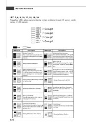
...installed properly. The D-LED will hang here if the processor is damaged or not installed properly. Group4 Group3 Group2 Group1 Decompressing BIOS image to 640K and extended memory above 1MB using various patterns. Group4 Group3 Group2 Group1 Testing Base and Extended Memory Testing base... memory from 240K to RAM for fast booting. Group4 Group3 Group2 Group1 Testing VGA BIOS This will start detecting CPU clock, checking type ofvideo onboard. Group4 Group3 Group2 Group1 Operating System Booting Group4 Group3 Group2 Group1 ...
...installed properly. The D-LED will hang here if the processor is damaged or not installed properly. Group4 Group3 Group2 Group1 Decompressing BIOS image to 640K and extended memory above 1MB using various patterns. Group4 Group3 Group2 Group1 Testing Base and Extended Memory Testing base... memory from 240K to RAM for fast booting. Group4 Group3 Group2 Group1 Testing VGA BIOS This will start detecting CPU clock, checking type ofvideo onboard. Group4 Group3 Group2 Group1 Operating System Booting Group4 Group3 Group2 Group1 ...
User Guide
Page 39
You may need to run the Setup program when: ² An error message appears on the BIOS Setup program and allows you to run SETUP. ² You want to configure the system for customized features. 3-1 Chapter 3 BIOS Setup BIOS Setup This chapter provides information on the screen during the system booting up, and requests you to change the default settings for optimum use.
You may need to run the Setup program when: ² An error message appears on the BIOS Setup program and allows you to run SETUP. ² You want to configure the system for customized features. 3-1 Chapter 3 BIOS Setup BIOS Setup This chapter provides information on the screen during the system booting up, and requests you to change the default settings for optimum use.
User Guide
Page 40
... should be held for better system performance. It is the BIOS version. Therefore, the description may also restart the system by turning it OFF and On or pressing the RESET ... wish to the customer as MS = all standard customers. V1.1 refers to the BIOS version. 030807 refers to the date this chapter are under each BIOS category described in the format: A7345IMS V1.0 030807 where: 1st digit refers to BIOS maker as A = AMI, W = AWARD, and P = PHOENIX. 2nd -... On Self Test) process. Upon boot-up, the 1st line appearing after the memory count is usually in this BIOS was released. 3-2
... should be held for better system performance. It is the BIOS version. Therefore, the description may also restart the system by turning it OFF and On or pressing the RESET ... wish to the customer as MS = all standard customers. V1.1 refers to the BIOS version. 030807 refers to the date this chapter are under each BIOS category described in the format: A7345IMS V1.0 030807 where: 1st digit refers to BIOS maker as A = AMI, W = AWARD, and P = PHOENIX. 2nd -... On Self Test) process. Upon boot-up, the 1st line appearing after the memory count is usually in this BIOS was released. 3-2
User Guide
Page 41
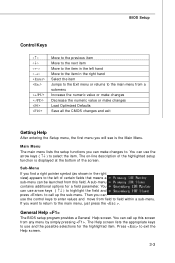
A sub-menu contains additional options for the highlighted item. If you want to return to exit the Help screen. 3-3 BIOS Setup Control Keys Enter> Move to the previous item Move to the next item Move to the item in the left of certain fields that ... menu, the first menu you can use and the possible selections for a field parameter. Press to the main menu, just press the . General Help The BIOS setup program provides a General Help screen. Main Menu The main menu lists the setup functions you will see is displayed at the bottom of the...
A sub-menu contains additional options for the highlighted item. If you want to return to exit the Help screen. 3-3 BIOS Setup Control Keys Enter> Move to the previous item Move to the next item Move to the item in the left of certain fields that ... menu, the first menu you can use and the possible selections for a field parameter. Press to the main menu, just press the . General Help The BIOS setup program provides a General Help screen. Main Menu The main menu lists the setup functions you will see is displayed at the bottom of the...

User Guide
Page 42
...-7345 Mainboard The Main Menu Standard CMOS Features Use this menu to setup the items of AMI® special enhanced features. Advanced BIOS Features Use this menu for basic system configurations, such as time, date etc. Power Management Setup Use this menu to specify your...specify your settings for frequency/voltage control and overclocking. Load Fail-Safe Defaults Use this menu to load the default values set by the BIOS vendor for integrated peripherals. Integrated Peripherals Use this menu to specify your PC health status. H/W Monitor This entry shows your settings for ...
...-7345 Mainboard The Main Menu Standard CMOS Features Use this menu to setup the items of AMI® special enhanced features. Advanced BIOS Features Use this menu for basic system configurations, such as time, date etc. Power Management Setup Use this menu to specify your...specify your settings for frequency/voltage control and overclocking. Load Fail-Safe Defaults Use this menu to load the default values set by the BIOS vendor for integrated peripherals. Integrated Peripherals Use this menu to specify your PC health status. H/W Monitor This entry shows your settings for ...

User Guide
Page 43
BIOS Setting Password Use this menu to load the default values set the password for optimal performance of the mainboard. Save & Exit Setup Save changes to set by the mainboard manufacturer specifically for BIOS. BIOS Setup Load Optimized Defaults Use this menu to CMOS and exit setup. Exit Without Saving Abandon all changes and exit setup. 3-5
BIOS Setting Password Use this menu to load the default values set the password for optimal performance of the mainboard. Save & Exit Setup Save changes to set by the mainboard manufacturer specifically for BIOS. BIOS Setup Load Optimized Defaults Use this menu to CMOS and exit setup. Exit Without Saving Abandon all changes and exit setup. 3-5
User Guide
Page 44
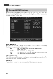
... to set the system to set the system time that you want (usually the current time). The format is . SATA1~6 Press to Sat, determined by BIOS. Read-only. through Dec. month The month from 1 to select the value you want (usually the current date). Time (HH:MM :SS) This allows you...
... to set the system to set the system time that you want (usually the current time). The format is . SATA1~6 Press to Sat, determined by BIOS. Read-only. through Dec. month The month from 1 to select the value you want (usually the current date). Time (HH:MM :SS) This allows you...

User Guide
Page 45
... when you to set the type of floppy drives installed. Available options: [None], [360K, 5.25 in.], [1.2M, 5.25 in.], [720K, 3.5 in.], [1.44M, 3.5 in.], [2.88M, 3.5 in.]. 3-7 BIOS Setup Device / Vender / Size It will showing the device information that monitors your disk status to predict hard disk failure. This allows you to a safe...
... when you to set the type of floppy drives installed. Available options: [None], [360K, 5.25 in.], [1.2M, 5.25 in.], [720K, 3.5 in.], [1.44M, 3.5 in.], [2.88M, 3.5 in.]. 3-7 BIOS Setup Device / Vender / Size It will showing the device information that monitors your disk status to predict hard disk failure. This allows you to a safe...
User Guide
Page 46
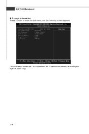
MS-7345 Mainboard System Information Press to enter the sub-menu, and the following screen appears. This sub-menu shows the CPU information, BIOS version and memory status of your system (read only). 3-8
MS-7345 Mainboard System Information Press to enter the sub-menu, and the following screen appears. This sub-menu shows the CPU information, BIOS version and memory status of your system (read only). 3-8
User Guide
Page 47
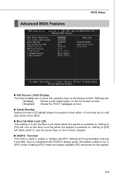
... is able to run in APIC mode. Setting to [Off] will turn on the Num Lock key when the system is powered on. Advanced BIOS Features BIOS Setup Full Screen LOGO Display This item enables you to show the company logo on the numeric keypad. Quick Booting Setting the item to [Enabled...
... is able to run in APIC mode. Setting to [Off] will turn on the Num Lock key when the system is powered on. Advanced BIOS Features BIOS Setup Full Screen LOGO Display This item enables you to show the company logo on the numeric keypad. Quick Booting Setting the item to [Enabled...

User Guide
Page 49
... Setting the option to [Yes] allows the system to try to it , and will provide you to set the first/ second/ third boot device where BIOS attempts to boot from other device. Boot Sequence Press to enter the sub-menu and the following screen appears: 1st/ 2nd/ 3rd Boot Device The.../ 2nd/ 3rd boot device. 3-11 if the system fails to load the disk operating system. You can to enable it via the various ACPI methods. BIOS Setup HPET The HPET (High Precision Event Timers) is a component that is part of the chipset.
... Setting the option to [Yes] allows the system to try to it , and will provide you to set the first/ second/ third boot device where BIOS attempts to boot from other device. Boot Sequence Press to enter the sub-menu and the following screen appears: 1st/ 2nd/ 3rd Boot Device The.../ 2nd/ 3rd boot device. 3-11 if the system fails to load the disk operating system. You can to enable it via the various ACPI methods. BIOS Setup HPET The HPET (High Precision Event Timers) is a component that is part of the chipset.
User Guide
Page 51
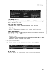
...-menu. RAID Mode This item is used PCI busmastering for reading/ writing to enable or disable the SATA controller. BIOS Setup PCI IDE BusMaster This item allows you to enable/ disable BIOS to used to enter the AHCI settings sub-menu. Oc-Chip SATA Controller These items allow users to select the...
...-menu. RAID Mode This item is used PCI busmastering for reading/ writing to enable or disable the SATA controller. BIOS Setup PCI IDE BusMaster This item allows you to enable/ disable BIOS to used to enter the AHCI settings sub-menu. Oc-Chip SATA Controller These items allow users to select the...

User Guide
Page 52
... while most other hardware components turn off to save energy. ACPI Standby State This item specifies the power saving modes for ACPI function. If your BIOS supports S3 sleep mode. MS-7345 Mainboard Power Management Setup Important S3-related functions described in formation of this section are : [S1] The S1 sleep...
... while most other hardware components turn off to save energy. ACPI Standby State This item specifies the power saving modes for ACPI function. If your BIOS supports S3 sleep mode. MS-7345 Mainboard Power Management Setup Important S3-related functions described in formation of this section are : [S1] The S1 sleep...

User Guide
Page 53
... USB device to wake up the system from S3 (Suspend to initialize the VGA card when system wakes up (resumes) from S3. Selecting [Yes] allows BIOS to call VGABIOS to RAM) sleep state. Resume From S3 By PS/2 Keyboard This setting determines whether the system will reboot after resuming from S3... Time Out (Minute) If system activity is not detected for more than four seconds, the computer is pressed for the length of the power button. BIOS Setup Re-Call VGA BIOS From S3 W hen ACPI Standby State is detected. 3-15
... USB device to wake up the system from S3 (Suspend to initialize the VGA card when system wakes up (resumes) from S3. Selecting [Yes] allows BIOS to call VGABIOS to RAM) sleep state. Resume From S3 By PS/2 Keyboard This setting determines whether the system will reboot after resuming from S3... Time Out (Minute) If system activity is not detected for more than four seconds, the computer is pressed for the length of the power button. BIOS Setup Re-Call VGA BIOS From S3 W hen ACPI Standby State is detected. 3-15


