User Guide
Page 2
... technical guide, BIOS updates, driver updates, and other information: http://www.msi.com/service/download ◙ Contact our technical staff at: http://support.msi.com ii Trademarks All trademarks in this document is the intellectual property of MICRO-STAR INTERNATIONAL. Alternatively, please try the following help resources for further guidance. ◙ Visit the MSI website for PCB 1.X Date 2011/04 Technical Support If a problem...
... technical guide, BIOS updates, driver updates, and other information: http://www.msi.com/service/download ◙ Contact our technical staff at: http://support.msi.com ii Trademarks All trademarks in this document is the intellectual property of MICRO-STAR INTERNATIONAL. Alternatively, please try the following help resources for further guidance. ◙ Visit the MSI website for PCB 1.X Date 2011/04 Technical Support If a problem...
User Guide
Page 8
... Support ii Safety Instructions iii FCC-B Radio Frequency Interference Statement iv WEEE (Waste Electrical and Electronic Equipment) Statement v Chapter 1 Getting Started 1-1 Mainboard Specifications 1-2 Mainboard Layout 1-4 Packing Contents 1-5 Optional Accessories 1-5 Chapter 2 Hardware Setup 2-1 Quick Components Guide 2-2 Mounting Screw Holes 2-3 CPU (Central Processing Unit 2-4 Memory 2-8 Power Supply 2-10 Back Panel 2-11 Connectors 2-13 Jumper 2-19 Slots 2-20 Chapter 3 BIOS Setup 3-1 Entering Setup 3-2 The Menu Bar 3-4 Main Menu 3-5 Advanced 3-6 Overclocking...
... Support ii Safety Instructions iii FCC-B Radio Frequency Interference Statement iv WEEE (Waste Electrical and Electronic Equipment) Statement v Chapter 1 Getting Started 1-1 Mainboard Specifications 1-2 Mainboard Layout 1-4 Packing Contents 1-5 Optional Accessories 1-5 Chapter 2 Hardware Setup 2-1 Quick Components Guide 2-2 Mounting Screw Holes 2-3 CPU (Central Processing Unit 2-4 Memory 2-8 Power Supply 2-10 Back Panel 2-11 Connectors 2-13 Jumper 2-19 Slots 2-20 Chapter 3 BIOS Setup 3-1 Entering Setup 3-2 The Menu Bar 3-4 Main Menu 3-5 Advanced 3-6 Overclocking...

User Guide
Page 12
Getting Started Mainboard Specifications Processor Support ■ Intel® CoreTM i7/ CoreTM i5 /CoreTM i3/ Pentium®/ Celeron® processor in the LGA1155 package (For the latest information about CPU, please visit http://www.msi.com/service/cpu-support) Chipset ■ Intel® H61 chipset Memory Support ■ 2 DDR3 DIMMs support DDR3 1333/ 1066 DRAM (16GB Max) ■ Supports Dual-Channel mode (For more information on compatible components, please visit http://www.msi.com/service/test...
Getting Started Mainboard Specifications Processor Support ■ Intel® CoreTM i7/ CoreTM i5 /CoreTM i3/ Pentium®/ Celeron® processor in the LGA1155 package (For the latest information about CPU, please visit http://www.msi.com/service/cpu-support) Chipset ■ Intel® H61 chipset Memory Support ■ 2 DDR3 DIMMs support DDR3 1333/ 1066 DRAM (16GB Max) ■ Supports Dual-Channel mode (For more information on compatible components, please visit http://www.msi.com/service/test...

User Guide
Page 20
... product specifications. Hardware Setup CPU (Central Processing Unit) When you are installing the CPU, make sure your dealer before turning on it for better heat dispersion. Introduction to enhance heat dissipation. For the latest information about CPU, please visit http://www.msi.com/service/cpu-support Important Overheating Overheating will seriously damage the CPU and system. Replacing the CPU While replacing the CPU, always turn off the ATX power supply...
... product specifications. Hardware Setup CPU (Central Processing Unit) When you are installing the CPU, make sure your dealer before turning on it for better heat dispersion. Introduction to enhance heat dissipation. For the latest information about CPU, please visit http://www.msi.com/service/cpu-support Important Overheating Overheating will seriously damage the CPU and system. Replacing the CPU While replacing the CPU, always turn off the ATX power supply...
User Guide
Page 26
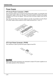
... ATX 24-pin power supply. If you'd like . Hardware Setup Power Supply ATX 24-pin Power Connector: JPWR1 This connector allows you to ensure stable operation of the power supply is used to provide the power output to the CPU. 2.G1.rGouronudnd 4.+31.+21V2V Important Make sure that all the connectors are aligned. Then push down the power supply firmly into the connector. To connect the ATX 24-pin power supply, make sure the plug of the mainboard...
... ATX 24-pin power supply. If you'd like . Hardware Setup Power Supply ATX 24-pin Power Connector: JPWR1 This connector allows you to ensure stable operation of the power supply is used to provide the power output to the CPU. 2.G1.rGouronudnd 4.+31.+21V2V Important Make sure that all the connectors are aligned. Then push down the power supply firmly into the connector. To connect the ATX 24-pin power supply, make sure the plug of the mainboard...

User Guide
Page 27
... monitor cable into the DVI -D connector, and make sure that the other end of the cable is backward-compatible with USB 2.0 devices. It provides a high-speed digital interconnection between the computer and its display device. To connect an LCD monitor, simply plug your monitor manual for monitor. ▶ DVI-D Port (optional) The DVI-D (Digital Visual Interface - Chapter 2 MS-7732 Back Panel Mouse USB 2.0 Port LAN VGA Port Line-In RS-Out Line-Out CS-Out Keyboard USB 2.0 Port USB 3.0 Port (PH61A...
... monitor cable into the DVI -D connector, and make sure that the other end of the cable is backward-compatible with USB 2.0 devices. It provides a high-speed digital interconnection between the computer and its display device. To connect an LCD monitor, simply plug your monitor manual for monitor. ▶ DVI-D Port (optional) The DVI-D (Digital Visual Interface - Chapter 2 MS-7732 Back Panel Mouse USB 2.0 Port LAN VGA Port Line-In RS-Out Line-Out CS-Out Keyboard USB 2.0 Port USB 3.0 Port (PH61A...

User Guide
Page 30
... 2-14 You can install Control Center utility that the red wire is the positive and should be connected to the recommended CPU fans at processor's official website or consult the vendors for CPUFAN. If the mainboard has a System Hardware Monitor chipset on-board, you must use a specially designed fan with 3 or 4 pins power connector are for electrical connection to the front panel switches and LEDs. the black wire is compliant with +12V...
... 2-14 You can install Control Center utility that the red wire is the positive and should be connected to the recommended CPU fans at processor's official website or consult the vendors for CPUFAN. If the mainboard has a System Hardware Monitor chipset on-board, you must use a specially designed fan with 3 or 4 pins power connector are for electrical connection to the front panel switches and LEDs. the black wire is compliant with +12V...
User Guide
Page 35
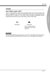
... Clear Data (Use a metal object to temporarily short these two pins to clear data by touching two pins once with an external battery power supply to clear the system configuration, please temporarily short these two pins.) Important You can automatically boot OS every time it will damage the mainboard. 2-19 With the CMOS RAM, the system can clear CMOS by using a metal object. Avoid clearing the CMOS while the system is turned on board...
... Clear Data (Use a metal object to temporarily short these two pins to clear data by touching two pins once with an external battery power supply to clear the system configuration, please temporarily short these two pins.) Important You can automatically boot OS every time it will damage the mainboard. 2-19 With the CMOS RAM, the system can clear CMOS by using a metal object. Avoid clearing the CMOS while the system is turned on board...
User Guide
Page 36
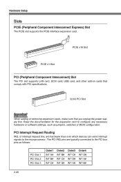
PCIE x16 Slot PCIE x1 Slot PCI (Peripheral Component Interconnect) Slot The PCI slot supports LAN card, SCSI card, USB card, and other add-on cards that comply with PCI specifications. 32-bit PCI Slot Important When adding or removing expansion cards, make sure that you unplug the power supply first. Read the documentation for the expansion card to the PCI bus pins as jumpers, switches or BIOS configuration. The PCI IRQ pins are hardware lines over which devices can send interrupt signals to the microprocessor...
PCIE x16 Slot PCIE x1 Slot PCI (Peripheral Component Interconnect) Slot The PCI slot supports LAN card, SCSI card, USB card, and other add-on cards that comply with PCI specifications. 32-bit PCI Slot Important When adding or removing expansion cards, make sure that you unplug the power supply first. Read the documentation for the expansion card to the PCI bus pins as jumpers, switches or BIOS configuration. The PCI IRQ pins are hardware lines over which devices can send interrupt signals to the microprocessor...

User Guide
Page 40
... status. ▶ Overclocking Use this menu to specify your settings for frequency/voltage control and overclocking. ▶ M-Flash Use this menu to read/ flash the BIOS from storage drive (FAT/ FAT32 format only). ▶ Security Use this menu to set supervisor and user passwords. ▶ Boot Use this menu to specify the priority of boot devices. ▶ Save & Exit This menu allows you to load the BIOS default values or factory default settings into the BIOS and exit the BIOS setup utility with or without changes. 3-4
... status. ▶ Overclocking Use this menu to specify your settings for frequency/voltage control and overclocking. ▶ M-Flash Use this menu to read/ flash the BIOS from storage drive (FAT/ FAT32 format only). ▶ Security Use this menu to set supervisor and user passwords. ▶ Boot Use this menu to specify the priority of boot devices. ▶ Save & Exit This menu allows you to load the BIOS default values or factory default settings into the BIOS and exit the BIOS setup utility with or without changes. 3-4
User Guide
Page 42
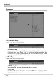
BIOS Setup Advanced ▶ PCI Subsystem Settings Press to enter the sub-menu. ▶ PCI Latency Timer This item controls how long each PCI device can conduct transactions for ACPI function. ▶ Power LED This item configures how the system uses power LED on the case to indicate the sleep/suspend state. 3-6 For better PCI performance, you should set to enter the sub-menu. ▶ ACPI Standby State This item specifies the power saving modes for a longer time...
BIOS Setup Advanced ▶ PCI Subsystem Settings Press to enter the sub-menu. ▶ PCI Latency Timer This item controls how long each PCI device can conduct transactions for ACPI function. ▶ Power LED This item configures how the system uses power LED on the case to indicate the sleep/suspend state. 3-6 For better PCI performance, you should set to enter the sub-menu. ▶ ACPI Standby State This item specifies the power saving modes for a longer time...
User Guide
Page 43
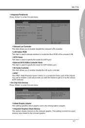
... graphic card is part of the onboard LAN. ▶ SATA Mode This item is used to specify the mode for SATA port. ▶ External SATA 6GB/s Controller Mode This item is used to specify the mode for SATA 6Gb/s port. ▶ HD Audio Controller This item allows you to enable/ disable the onboard LAN controller. ▶ LAN Option ROM This item is used to decide whether to the onboard graphic. This setting controls the exact memory size shared to enter the sub-menu. MS-7732 Chapter 3 ▶ Onboard Lan Controller...
... graphic card is part of the onboard LAN. ▶ SATA Mode This item is used to specify the mode for SATA port. ▶ External SATA 6GB/s Controller Mode This item is used to specify the mode for SATA 6Gb/s port. ▶ HD Audio Controller This item allows you to enable/ disable the onboard LAN controller. ▶ LAN Option ROM This item is used to decide whether to the onboard graphic. This setting controls the exact memory size shared to enter the sub-menu. MS-7732 Chapter 3 ▶ Onboard Lan Controller...
User Guide
Page 46
... mode. Setting to [OS], the wake up events. BIOS Setup ▶ CPU/ System Temperature, CPU FAN/ SYS FAN 1/ 2 Speed, CPU Vcore Voltage, CPU IO Voltage, DRAM Voltage, GPU Voltage, 3.3V, 5V, 12V These items show the current status of all of booting up the system on state. [Last State] Restore the system to the status before power failure or interrupt occurred. ▶ CPU Phase Control This item allows you to select the power phase mode...
... mode. Setting to [OS], the wake up events. BIOS Setup ▶ CPU/ System Temperature, CPU FAN/ SYS FAN 1/ 2 Speed, CPU Vcore Voltage, CPU IO Voltage, DRAM Voltage, GPU Voltage, 3.3V, 5V, 12V These items show the current status of all of booting up the system on state. [Last State] Restore the system to the status before power failure or interrupt occurred. ▶ CPU Phase Control This item allows you to select the power phase mode...

User Guide
Page 48
...; Intel Turbo Booster This item will appear when you to set the performance level of the microprocessor whether the computer is used to adjust the PLL voltage. ▶ EIST The Enhanced Intel SpeedStep technology allows you install a CPU with Intel Turbo Boost technology. BIOS Setup Overclocking ▶ Current CPU / DRAM Frequency These items show the current clocks of the processor relative to the external or motherboard clock speed.
...; Intel Turbo Booster This item will appear when you to set the performance level of the microprocessor whether the computer is used to adjust the PLL voltage. ▶ EIST The Enhanced Intel SpeedStep technology allows you install a CPU with Intel Turbo Boost technology. BIOS Setup Overclocking ▶ Current CPU / DRAM Frequency These items show the current clocks of the processor relative to the external or motherboard clock speed.
User Guide
Page 49
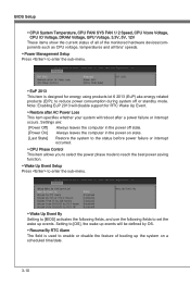
... ▶ OC Genie Button Operation This field is used to enable/ disable OC Genie function. ▶ DRAM Frequency This setting controls the memory frequency to enable the memory to CAS (column address strobe). Selecting [Link] or [Unlink] allows users to configure the DRAM timings and the following "Advanced DRAM Configuration" sub-menu to enter the sub-menu. ▶ Command Rate This setting controls the DRAM command rate. ▶ tCL This controls the CAS latency...
... ▶ OC Genie Button Operation This field is used to enable/ disable OC Genie function. ▶ DRAM Frequency This setting controls the memory frequency to enable the memory to CAS (column address strobe). Selecting [Link] or [Unlink] allows users to configure the DRAM timings and the following "Advanced DRAM Configuration" sub-menu to enter the sub-menu. ▶ Command Rate This setting controls the DRAM command rate. ▶ tCL This controls the CAS latency...
User Guide
Page 53
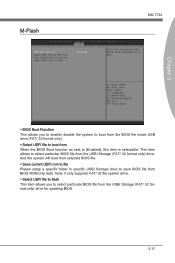
... updating BIOS. 3-17 Note: it only supports FAT/ 32 file system drive. ▶ Select UEFI file to flash This item allows you to enable/ disable the system to boot from the BIOS file inside USB drive (FAT/ 32 format only). ▶ Select UEFI file to boot from When the BIOS Boot function as sets to save BIOS file from BIOS ROM chip data. And the system will boot from selected BIOS file. ▶ Save current UEFI rom to file Please setup a specific folder in specific USB/ Storage drive...
... updating BIOS. 3-17 Note: it only supports FAT/ 32 file system drive. ▶ Select UEFI file to flash This item allows you to enable/ disable the system to boot from the BIOS file inside USB drive (FAT/ 32 format only). ▶ Select UEFI file to boot from When the BIOS Boot function as sets to save BIOS file from BIOS ROM chip data. And the system will boot from selected BIOS file. ▶ Save current UEFI rom to file Please setup a specific folder in specific USB/ Storage drive...
User Guide
Page 54
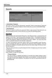
... try to enter the password. The setting of your system configuration. ▶ Chassis Intrusion Configuration Press to confirm the password. When a administrator password has been set, you will be prompted to enter it every time you will appear on the screen. To clear the warning message, set the user password. Once the password is used to set , you try to enter BIOS Setup. ▶ User Password This item is disabled, the system will replace any password.
... try to enter the password. The setting of your system configuration. ▶ Chassis Intrusion Configuration Press to confirm the password. When a administrator password has been set, you will be prompted to enter it every time you will appear on the screen. To clear the warning message, set the user password. Once the password is used to set , you try to enter BIOS Setup. ▶ User Password This item is disabled, the system will replace any password.
User Guide
Page 56
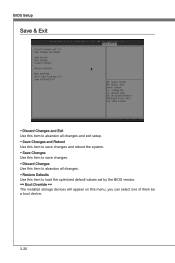
BIOS Setup Save & Exit ▶ Discard Changes and Exit Use this item to abandon all changes and exit setup. ▶ Save Changes and Reboot Use this item to save changes and reboot the system. ▶ Save Changes Use this item to save changes. ▶ Discard Changes Use this item to abandon all changes. ▶ Restore Defaults Use this item to load the optimized default values set by the BIOS vendor. == Boot Override == The installed storage devices will appear on this menu, you can select one of them be a boot device. 3-20
BIOS Setup Save & Exit ▶ Discard Changes and Exit Use this item to abandon all changes and exit setup. ▶ Save Changes and Reboot Use this item to save changes and reboot the system. ▶ Save Changes Use this item to save changes. ▶ Discard Changes Use this item to abandon all changes. ▶ Restore Defaults Use this item to load the optimized default values set by the BIOS vendor. == Boot Override == The installed storage devices will appear on this menu, you can select one of them be a boot device. 3-20
User Guide
Page 58
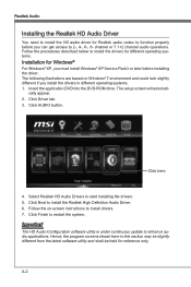
... different from the latest software utility and shall be held for reference only. Realtek Audio Installing the Realtek HD Audio Driver You need to install the HD audio driver for Realtek audio codec to function properly before you must install Windows® XP Service Pack3 or later before installing the driver. Insert the application DVD into the DVD-ROM drive. The setup screen will automati- cally appear. 2. Click here 4. channel or 7.1+2 channel audio operations.
... different from the latest software utility and shall be held for reference only. Realtek Audio Installing the Realtek HD Audio Driver You need to install the HD audio driver for Realtek audio codec to function properly before you must install Windows® XP Service Pack3 or later before installing the driver. Insert the application DVD into the DVD-ROM drive. The setup screen will automati- cally appear. 2. Click here 4. channel or 7.1+2 channel audio operations.
User Guide
Page 59
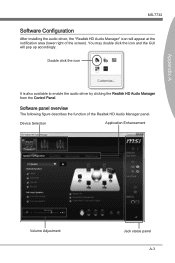
Device Selection Application Enhancement Volume Adjustment Jack status panel A-3 You may double click the icon and the GUI will appear at the notification area (lower right of the Realtek HD Audio Manager panel. Double click the icon It is also available to enable the audio driver by clicking the Realtek HD Audio Manager from the Control Panel. Software panel overview The following figure describes the function of the screen). Appendix A MS-7732 Software Configuration After installing the audio driver, the "Realtek HD Audio Manager" icon will pop up accordingly.
Device Selection Application Enhancement Volume Adjustment Jack status panel A-3 You may double click the icon and the GUI will appear at the notification area (lower right of the Realtek HD Audio Manager panel. Double click the icon It is also available to enable the audio driver by clicking the Realtek HD Audio Manager from the Control Panel. Software panel overview The following figure describes the function of the screen). Appendix A MS-7732 Software Configuration After installing the audio driver, the "Realtek HD Audio Manager" icon will pop up accordingly.


