User Guide
Page 1
... that may cause harmful interference to radio communications. These limits are designed to provide reasonable protection against harmful interference in accordance with the emission limits. Micro-Star International MS-7211 This device complies with the limits for a class B digital device, pursuant to part 15 of the FCC rules. However, there is...
... that may cause harmful interference to radio communications. These limits are designed to provide reasonable protection against harmful interference in accordance with the emission limits. Micro-Star International MS-7211 This device complies with the limits for a class B digital device, pursuant to part 15 of the FCC rules. However, there is...
User Guide
Page 2
... in the United States and/or other countries. PS/2 and OS® 2 are under continual improvement and we reserve the right to the correctness of MICRO-STAR INTERNATIONAL. Kensington and MicroSaver are registered trademarks or trademarks of International Business Machines Corporation. Revision History Revision Revision History V1.0 First release V1.1 Japanese...
... in the United States and/or other countries. PS/2 and OS® 2 are under continual improvement and we reserve the right to the correctness of MICRO-STAR INTERNATIONAL. Kensington and MicroSaver are registered trademarks or trademarks of International Business Machines Corporation. Revision History Revision Revision History V1.0 First release V1.1 Japanese...

User Guide
Page 3
The openings on it may damage the equipment. Place the power cord such a way that could damage or cause electrical shock. 11. All cautions and warnings on card or module. 9. The power cord or plug is incorrectly replaced. The equipment has been exposed to User Manual. - iii Do not cover the openings. 6. The equipment has dropped and damaged. - Do not leave this equipment on a reliable flat surface before setting it work well or you can not step on the enclosure are for future reference. 3. Lay this equipment in an environment unconditioned, storage ...
The openings on it may damage the equipment. Place the power cord such a way that could damage or cause electrical shock. 11. All cautions and warnings on card or module. 9. The power cord or plug is incorrectly replaced. The equipment has been exposed to User Manual. - iii Do not cover the openings. 6. The equipment has dropped and damaged. - Do not leave this equipment on a reliable flat surface before setting it work well or you can not step on the enclosure are for future reference. 3. Lay this equipment in an environment unconditioned, storage ...
User Guide
Page 7
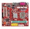
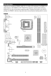
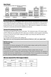
Designed for optimal system efficiency. Layout 1 The PM8M3-V is design based on VIA® P4M800 & VIA® VT8237R Plus chipsets for the Intel® P4 processors supporting Hyper-Threading Technology in the LGA775 package, the PM8M3-V delivers a high performance and professional desktop platform solution. Introduction Thank you for choosing the PM8M3-V (MS-7211 v1.x) Micro-ATX mainboard.
Designed for optimal system efficiency. Layout 1 The PM8M3-V is design based on VIA® P4M800 & VIA® VT8237R Plus chipsets for the Intel® P4 processors supporting Hyper-Threading Technology in the LGA775 package, the PM8M3-V delivers a high performance and professional desktop platform solution. Introduction Thank you for choosing the PM8M3-V (MS-7211 v1.x) Micro-ATX mainboard.

User Guide
Page 8
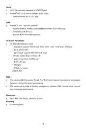
... • Can connect up to 3.2GHz, and Intel P4 Prescott Celeron CPU. (For the latest information about CPU, please visit http://www.msi.com.tw/program/products/mainboard/mbd/pro_mbd_cpu_support.php ) Chipset • VIA® P4M800CE chipset - ACPI & PC2001 compliant enhanced power management - ...Supports up to 2GB PC3200 (DDR400) SDRAMs. • Supports 2.5v DDR SDRAM. (For the updated supporting memory modules, please visit http://www.msi.com.tw/program/products/mainboard/mbd/pro_mbd_trp_list.php ) Slots • One AGP (Accelerated Graphics Port) 8x slot. • Two PCI 2.2 32...
... • Can connect up to 3.2GHz, and Intel P4 Prescott Celeron CPU. (For the latest information about CPU, please visit http://www.msi.com.tw/program/products/mainboard/mbd/pro_mbd_cpu_support.php ) Chipset • VIA® P4M800CE chipset - ACPI & PC2001 compliant enhanced power management - ...Supports up to 2GB PC3200 (DDR400) SDRAMs. • Supports 2.5v DDR SDRAM. (For the updated supporting memory modules, please visit http://www.msi.com.tw/program/products/mainboard/mbd/pro_mbd_trp_list.php ) Slots • One AGP (Accelerated Graphics Port) 8x slot. • Two PCI 2.2 32...
User Guide
Page 9
Compliance with PCI 2.2. - Supports ACPI Power Management. Compliance with AC'97 v2.2 spec. Dimension • Micro-ATX Form Factor: 245mm x 210mm Mounting • 6 mounting holes. 3 LAN • Realtek® 8100C / 8110SB (optional). - Supports 10Mb/s, 100Mb/s and 1000Mbs(1000Mbs for 8110SB only). - On-...
Compliance with PCI 2.2. - Supports ACPI Power Management. Compliance with AC'97 v2.2 spec. Dimension • Micro-ATX Form Factor: 245mm x 210mm Mounting • 6 mounting holes. 3 LAN • Realtek® 8100C / 8110SB (optional). - Supports 10Mb/s, 100Mb/s and 1000Mbs(1000Mbs for 8110SB only). - On-...
User Guide
Page 10
... DDR 333 OK OK DDR 400 OK OK 4 Central Processing Unit: CPU The mainboard supports Intel® Pentium 4 processor. MSI Reminds You... For the latest information about CPU, please visit http://www.msi.com.tw/program/products/mainboard/mbd/pro_mbd_cpu_support.php. We do not have the CPU cooler, contact your components are...
... DDR 333 OK OK DDR 400 OK OK 4 Central Processing Unit: CPU The mainboard supports Intel® Pentium 4 processor. MSI Reminds You... For the latest information about CPU, please visit http://www.msi.com.tw/program/products/mainboard/mbd/pro_mbd_cpu_support.php. We do not have the CPU cooler, contact your components are...
User Guide
Page 11
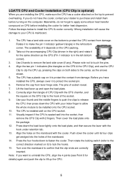
Wrong installation will cause the damage to protect the socket pin. 6. Before you have the cooler, contact your index finger to allow the whole module to fasten the cooler. The pins of the mainboard. 14. Then cover the load plate onto the package. 12. Lift the load lever up the CPU. 5 Use your thumb and the middle fingers to push the clips to release the CPU, then press down to be installed onto the CPU socket. 10. Align the holes on the CPU packing. 2. Press the four hooks down the CPU with your dealer to the center, as the CPU (Pin 1 indicator is in the left -...
Wrong installation will cause the damage to protect the socket pin. 6. Before you have the cooler, contact your index finger to allow the whole module to fasten the cooler. The pins of the mainboard. 14. Then cover the load plate onto the package. 12. Lift the load lever up the CPU. 5 Use your thumb and the middle fingers to push the clips to release the CPU, then press down to be installed onto the CPU socket. 10. Align the holes on the CPU packing. 2. Press the four hooks down the CPU with your dealer to the center, as the CPU (Pin 1 indicator is in the left -...
User Guide
Page 12
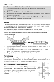
...the power supply firmly into the DIMM slot. Memory modules can install either single- A 300W or above power supply is suggested. 12 24 ATX 24-Pin Power Connector: CONN1 This connector allows you do not plug/unplug the CPU too often. Please note that no damage will be ...installed. (For the updated supporting memory modules, please visit http://www.msi.com.tw/program/products/mainboard/mbd/pro_mbd_trp_list.php) Install at each side of the DIMM slot will only fit in the right orientation. 2. You...
...the power supply firmly into the DIMM slot. Memory modules can install either single- A 300W or above power supply is suggested. 12 24 ATX 24-Pin Power Connector: CONN1 This connector allows you do not plug/unplug the CPU too often. Please note that no damage will be ...installed. (For the updated supporting memory modules, please visit http://www.msi.com.tw/program/products/mainboard/mbd/pro_mbd_trp_list.php) Install at each side of the DIMM slot will only fit in the right orientation. 2. You...

User Guide
Page 13
...the second drive to Slave mode by setting the jumper accordingly. MSI Reminds You... Please do not fold the serial ATA cable in connector. You may use the 20-pin ATX power supply as you like to use the 20-pin ATX power supply, please plug your power supply along with Serial ...IDE1/IDE2 The mainboard has dual Ultra DMA 66/100/133 controller that provides PIO mode 0~4, Bus Master, and Ultra DMA 66/100/133 function. MSI Reminds You... Serial ATA Connectors controlled by hard disk vendors for jumper setting instructions. CD In Connector: CD_IN1 R The connector is for CD-ROM ...
...the second drive to Slave mode by setting the jumper accordingly. MSI Reminds You... Please do not fold the serial ATA cable in connector. You may use the 20-pin ATX power supply as you like to use the 20-pin ATX power supply, please plug your power supply along with Serial ...IDE1/IDE2 The mainboard has dual Ultra DMA 66/100/133 controller that provides PIO mode 0~4, Bus Master, and Ultra DMA 66/100/133 function. MSI Reminds You... Serial ATA Connectors controlled by hard disk vendors for jumper setting instructions. CD In Connector: CD_IN1 R The connector is for CD-ROM ...
User Guide
Page 14
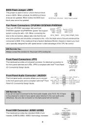
... fan) support system cooling fan with +12V. JFP2 is used to GND. When locked, the BIOS boot block area cannot be updated. MSI Reminds You... Reset HDD Switch LED 9 1 10 2 PowerPower Switch LED JFP2 Front Panel Audio Connector: JAUDIO1 The front panel audio connector ... JUSB1/JUSB2 The mainboard provides two standard USB 2.0 pin headers JUSB1&JUSB2. AUD_RET_L Key AUD_RET_R AUD_VCC AUD_GND 10 9 21 AUD_FPOUT_L HP_ON AUD_FPOUT_R AUD_MIC_BIAS AUD_MIC MSI Reminds You... 10 9 If you do not want to connect to the front audio header, pins 5 & 6, 9 & 10 have signal output ...
... fan) support system cooling fan with +12V. JFP2 is used to GND. When locked, the BIOS boot block area cannot be updated. MSI Reminds You... Reset HDD Switch LED 9 1 10 2 PowerPower Switch LED JFP2 Front Panel Audio Connector: JAUDIO1 The front panel audio connector ... JUSB1/JUSB2 The mainboard provides two standard USB 2.0 pin headers JUSB1&JUSB2. AUD_RET_L Key AUD_RET_R AUD_VCC AUD_GND 10 9 21 AUD_FPOUT_L HP_ON AUD_FPOUT_R AUD_MIC_BIAS AUD_MIC MSI Reminds You... 10 9 If you do not want to connect to the front audio header, pins 5 & 6, 9 & 10 have signal output ...

User Guide
Page 15
MSI Reminds You... Both are 16550A high speed communication ports that the pins of VCC & GND must be connected correctly or it is an interface specification ... mainboard offers one 9-pin male DIN connector COM 1 (on the rear panel), and one optional serial port COM2. If you unplug the power supply first. MSI Reminds You... Avoid clearing the CMOS while the system is ideal for the throughput demands of 3D graphics.
MSI Reminds You... Both are 16550A high speed communication ports that the pins of VCC & GND must be connected correctly or it is an interface specification ... mainboard offers one 9-pin male DIN connector COM 1 (on the rear panel), and one optional serial port COM2. If you unplug the power supply first. MSI Reminds You... Avoid clearing the CMOS while the system is ideal for the throughput demands of 3D graphics.

User Guide
Page 16
H/W Monitor 10 You may also restart the system by turning it OFF and On or pressing the RESET button. Advanced Chipset Features Use this menu to change the values in the chipset registers and optimize your settings for integrated peripherals. Integrated Peripherals Use this menu to specify your system performance. Power Management Setup Use this menu to setup the items of interrupt request line and pronounced I-R-Q, are typically connected to the PCI bus INT A# ~ INT D# pins as time, date etc. PNP/PCI Configurations This entry appears if your settings for basic ...
H/W Monitor 10 You may also restart the system by turning it OFF and On or pressing the RESET button. Advanced Chipset Features Use this menu to change the values in the chipset registers and optimize your settings for integrated peripherals. Integrated Peripherals Use this menu to specify your system performance. Power Management Setup Use this menu to setup the items of interrupt request line and pronounced I-R-Q, are typically connected to the PCI bus INT A# ~ INT D# pins as time, date etc. PNP/PCI Configurations This entry appears if your settings for basic ...

User Guide
Page 17
... Enabled for EMI reduction. Save & Exit Setup Save changes to load factory default settings into the BIOS for frequency/voltage control. Spread Spectrum When the motherboard's clock generator pulses, the extreme values (spikes) of . The Spread Spectrum function reduces the EMI generated by EMI, set to auto detect the DIMM and...
... Enabled for EMI reduction. Save & Exit Setup Save changes to load factory default settings into the BIOS for frequency/voltage control. Spread Spectrum When the motherboard's clock generator pulses, the extreme values (spikes) of . The Spread Spectrum function reduces the EMI generated by EMI, set to auto detect the DIMM and...

User Guide
Page 18
Setting options: 1.5V to increase the performance of your AGP display card when overclocking, but the stability may cause a stability issue, so changing the DDR voltage for long-term purpose is adjustable in MHz) and overclock the processor by the mainboard manufacturer for the stable performance. 12 Load Optimized Defaults You can increase the DDR speed. AGP Voltage AGP voltage is NOT recommended. Any changes made to a higher frequency. Adjust CPU/AGP/PCI Frequency This item allows you to select the CPU/AGP/PCI Front Side Bus clock frequency (in the field, allowing you to 1....
Setting options: 1.5V to increase the performance of your AGP display card when overclocking, but the stability may cause a stability issue, so changing the DDR voltage for long-term purpose is adjustable in MHz) and overclock the processor by the mainboard manufacturer for the stable performance. 12 Load Optimized Defaults You can increase the DDR speed. AGP Voltage AGP voltage is NOT recommended. Any changes made to a higher frequency. Adjust CPU/AGP/PCI Frequency This item allows you to select the CPU/AGP/PCI Front Side Bus clock frequency (in the field, allowing you to 1....
User Guide
Page 64
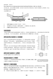
DDR DIMM 2. 将 DDR DDR 3. http://www.msi.com.tw/program/products/mainboard/mbd/pro_mbd_trp_list.php DDR 内存 Volt Notch 1. DIMM ATX 300W 12 24 ATX 24-Pin CONN1 ATX 24-Pin ATX 24-Pin 20-pin 的 ATX 20-pin 的 ATX pin 1 和 pin 13 pin 11, 12, 23 和 24 NC +...12V 5VSB PWR OK GND +5V GND +5V GND +3.3V +3.3V 1 13 GND +5V +5V +5V Res GND GND GND PS-ON# GND -12V +3.3V ATX 12V JPW1 12V 此 12V CPU 供电。 12V FDD1 1 FDD1,支持 360K, 720K, 1.2M, 1.44M 和 2.88M 42 31...
DDR DIMM 2. 将 DDR DDR 3. http://www.msi.com.tw/program/products/mainboard/mbd/pro_mbd_trp_list.php DDR 内存 Volt Notch 1. DIMM ATX 300W 12 24 ATX 24-Pin CONN1 ATX 24-Pin ATX 24-Pin 20-pin 的 ATX 20-pin 的 ATX pin 1 和 pin 13 pin 11, 12, 23 和 24 NC +...12V 5VSB PWR OK GND +5V GND +5V GND +3.3V +3.3V 1 13 GND +5V +5V +5V Res GND GND GND PS-ON# GND -12V +3.3V ATX 12V JPW1 12V 此 12V CPU 供电。 12V FDD1 1 FDD1,支持 360K, 720K, 1.2M, 1.44M 和 2.88M 42 31...
User Guide
Page 65
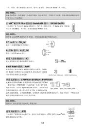
Slave 由 VIA® 8237R Plus 控制的 Serial ATA 接口:SATA1/SATA2 2 Serial ATA Serial ATA 150 MB/s Serial ATA1.0 规格。 serial ATA 90 CD In 接口:CD_IN1 R CD-ROM GND L AUX In 接口:AUX_IN1 aux-in 接口。 JC1 2 L GND R 2 GND 1 CINTRO BIOS Flash 跳线:JWP1 BIOS BIOS BIOS 2 2 1 1 BIOS Flash Unlocked BIOS Flash Locked CPUFAN1/SYSFAN1/PWRFAN1 此 4-pin 的 CPUFAN1 3-pin 的 SYSFAN1 PWRFAN1 12V 3-...
Slave 由 VIA® 8237R Plus 控制的 Serial ATA 接口:SATA1/SATA2 2 Serial ATA Serial ATA 150 MB/s Serial ATA1.0 规格。 serial ATA 90 CD In 接口:CD_IN1 R CD-ROM GND L AUX In 接口:AUX_IN1 aux-in 接口。 JC1 2 L GND R 2 GND 1 CINTRO BIOS Flash 跳线:JWP1 BIOS BIOS BIOS 2 2 1 1 BIOS Flash Unlocked BIOS Flash Locked CPUFAN1/SYSFAN1/PWRFAN1 此 4-pin 的 CPUFAN1 3-pin 的 SYSFAN1 PWRFAN1 12V 3-...

User Guide
Page 66
JAUDIO1 AUD_RET_L 10 9 AUD_FPOUT_L JAUDIO1 Key AUD_RET_R 符合 Intel® I/O AUD_VCC AUD_GND HP_ON AUD_FPOUT_R AUD_MIC_BIAS AUD_MIC 21 10 9 5 & 6, 9 & 10 Line-Out 21 前置 USB 接口:JUSB1/JUSB2 2 个 USB2.0 的接口 JUSB1、JUSB2。USB 2.0 480Mbps,是 USB1.1 的 40 USB USB HDD MP3 (9)Key (10)USB0C USB0+ GND USB0- VCC(1) VCC(2) GND USB1USB1+ VCC 和 GND COM 2 RTS SOUT GND 1 个 9-pin 公头 DIN COM1 9]RI 和另 1 ...
JAUDIO1 AUD_RET_L 10 9 AUD_FPOUT_L JAUDIO1 Key AUD_RET_R 符合 Intel® I/O AUD_VCC AUD_GND HP_ON AUD_FPOUT_R AUD_MIC_BIAS AUD_MIC 21 10 9 5 & 6, 9 & 10 Line-Out 21 前置 USB 接口:JUSB1/JUSB2 2 个 USB2.0 的接口 JUSB1、JUSB2。USB 2.0 480Mbps,是 USB1.1 的 40 USB USB HDD MP3 (9)Key (10)USB0C USB0+ GND USB0- VCC(1) VCC(2) GND USB1USB1+ VCC 和 GND COM 2 RTS SOUT GND 1 个 9-pin 公头 DIN COM1 9]RI 和另 1 ...
User Guide
Page 76
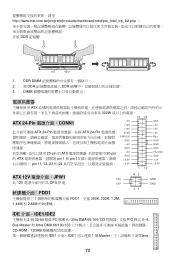
... +12V 5VSB PWR OK GND +5V GND +5V GND +3.3V +3.3V GND +5V +5V +5V Res GND GND GND PS-ON# GND -12V +3.3V 1 13 ATX 12V JPW1 12V 此 12V CPU 供電。 12V FDD1 1 FDD1,支援 360K, 720K, 1.2M, 1.44M 和 2.88M 42 31 GND GND...;式 0~4, Bus Master 和 Ultra DMA 66/100/133 4 CD-ROM、120MB IDE1 介面。IDE1 1 個 Master 1 個 Slave 70 http://www.msi.com.tw/program/products/mainboard/mbd/pro_mbd_trp_list.php DDR 記憶體 Volt Notch 1. DDR DIMM 2. 將 DDR DDR 3.
... +12V 5VSB PWR OK GND +5V GND +5V GND +3.3V +3.3V GND +5V +5V +5V Res GND GND GND PS-ON# GND -12V +3.3V 1 13 ATX 12V JPW1 12V 此 12V CPU 供電。 12V FDD1 1 FDD1,支援 360K, 720K, 1.2M, 1.44M 和 2.88M 42 31 GND GND...;式 0~4, Bus Master 和 Ultra DMA 66/100/133 4 CD-ROM、120MB IDE1 介面。IDE1 1 個 Master 1 個 Slave 70 http://www.msi.com.tw/program/products/mainboard/mbd/pro_mbd_trp_list.php DDR 記憶體 Volt Notch 1. DDR DIMM 2. 將 DDR DDR 3.
User Guide
Page 77
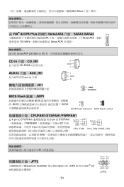
Slave 由 VIA® 8237R Plus 控制的 Serial ATA 介面:SATA1/SATA2 2 Serial ATA Serial ATA 150 MB/s Serial ATA1.0 規格。 serial ATA 90 CD In 介面:CD_IN1 R CD-ROM GND L AUX In 介面:AUX_IN1 aux-in 介面。 JC1 2 L GND R 2 GND 1 CINTRO BIOS Flash 跳線:JWP1 BIOS BIOS BIOS 2 2 1 1 BIOS Flash Unlocked BIOS Flash Locked CPUFAN1/SYSFAN1/PWRFAN1 此 4-pin 的 CPUFAN1 3-pin 的 SYSFAN1 PWRFAN1 12V 3-...
Slave 由 VIA® 8237R Plus 控制的 Serial ATA 介面:SATA1/SATA2 2 Serial ATA Serial ATA 150 MB/s Serial ATA1.0 規格。 serial ATA 90 CD In 介面:CD_IN1 R CD-ROM GND L AUX In 介面:AUX_IN1 aux-in 介面。 JC1 2 L GND R 2 GND 1 CINTRO BIOS Flash 跳線:JWP1 BIOS BIOS BIOS 2 2 1 1 BIOS Flash Unlocked BIOS Flash Locked CPUFAN1/SYSFAN1/PWRFAN1 此 4-pin 的 CPUFAN1 3-pin 的 SYSFAN1 PWRFAN1 12V 3-...
