User Manual
Page 3
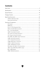
... Components 23 CPU Socket...24 DIMM Slots...25 PCI_E1~3: PCIe Expansion Slots 26 SATA_5~8: SATA 6Gb/s Connectors 26 M2_1~2: M.2 Slots (Key M 27 JAUD1: Front Audio Connector 30 JFP1, JFP2: Front Panel Connectors 30 JCI1: Chassis Intrusion Connector 31 CPU_PWR1, ATX_PWR1: Power Connectors 32 JCOM1: Serial Port Connector 33 JLPT1: Parallel Port Connector 33 JUSB3: USB 3.2 Gen 1 Connector 34 JUSB1~2: USB 2.0 Connectors 35 JTPM1: TPM Module Connector 35 CPU_FAN1, SYS_FAN1~2: Fan Connectors 36 JBAT1: Clear CMOS (Reset BIOS) Jumper 37 BAT1: CMOS Battery 37 JRGB1: RGB LED connector 38...
... Components 23 CPU Socket...24 DIMM Slots...25 PCI_E1~3: PCIe Expansion Slots 26 SATA_5~8: SATA 6Gb/s Connectors 26 M2_1~2: M.2 Slots (Key M 27 JAUD1: Front Audio Connector 30 JFP1, JFP2: Front Panel Connectors 30 JCI1: Chassis Intrusion Connector 31 CPU_PWR1, ATX_PWR1: Power Connectors 32 JCOM1: Serial Port Connector 33 JLPT1: Parallel Port Connector 33 JUSB3: USB 3.2 Gen 1 Connector 34 JUSB1~2: USB 2.0 Connectors 35 JTPM1: TPM Module Connector 35 CPU_FAN1, SYS_FAN1~2: Fan Connectors 36 JBAT1: Clear CMOS (Reset BIOS) Jumper 37 BAT1: CMOS Battery 37 JRGB1: RGB LED connector 38...

User Manual
Page 5
Quick Start Thank you for purchasing a new motherboard from MSI®. Preparing Tools and Components Intel® LGA1700 CPU LGA1700 CPU Fan Chassis DDR4 Memory Power Supply Unit Graphics Card Thermal Paste SATA Hard Disk Drive Phillips Screwdriver A Package of the installations also provide video demonstrations. This Quick Start section provides demonstration diagrams about how to install your phone or tablet. You may have even link to watch it with the web browser on your computer. Please link to the URL to the URL by scanning the QR code. Some of Screws 3
Quick Start Thank you for purchasing a new motherboard from MSI®. Preparing Tools and Components Intel® LGA1700 CPU LGA1700 CPU Fan Chassis DDR4 Memory Power Supply Unit Graphics Card Thermal Paste SATA Hard Disk Drive Phillips Screwdriver A Package of the installations also provide video demonstrations. This Quick Start section provides demonstration diagrams about how to install your phone or tablet. You may have even link to watch it with the web browser on your computer. Please link to the URL to the URL by scanning the QR code. Some of Screws 3
User Manual
Page 6
... yourself of the following instructions to ensure successful computer assembly. ∙ Ensure that there are prone to the user. ∙ If you need help during any installation step, please consult a certified computer technician. ∙ Always turn off the power supply and unplug the power cord from electrostatic discharge (ESD). Loose connections may damage the motherboard. 4 Do not place anything...
... yourself of the following instructions to ensure successful computer assembly. ∙ Ensure that there are prone to the user. ∙ If you need help during any installation step, please consult a certified computer technician. ∙ Always turn off the power supply and unplug the power cord from electrostatic discharge (ESD). Loose connections may damage the motherboard. 4 Do not place anything...

User Manual
Page 17
... Max speed up to 4000+ MHz ∙ Supports Dual-Channel mode ∙ Supports non-ECC, un-buffered memory ∙ Supports Intel® Extreme Memory Profile (XMP) * Please refer to get the newest support status as new processors are released. Specifications CPU Chipset Memory Expansion Slots Onboard Graphics SATA Ports ∙ Supports Intel® Core™ 14th/ 13th/ 12th Gen Processors, Intel® Pentium® Gold and Celeron® Processors* ∙ Processor socket LGA1700 * Please go to www.msi...
... Max speed up to 4000+ MHz ∙ Supports Dual-Channel mode ∙ Supports non-ECC, un-buffered memory ∙ Supports Intel® Extreme Memory Profile (XMP) * Please refer to get the newest support status as new processors are released. Specifications CPU Chipset Memory Expansion Slots Onboard Graphics SATA Ports ∙ Supports Intel® Core™ 14th/ 13th/ 12th Gen Processors, Intel® Pentium® Gold and Celeron® Processors* ∙ Processor socket LGA1700 * Please go to www.msi...
User Manual
Page 18
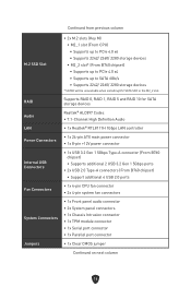
...RAID Supports RAID 0, RAID 1, RAID 5 and RAID 10 for SATA storage devices Audio Realtek® ALC897 Codec ∙ 7.1-Channel High Definition Audio LAN ∙ 1x Realtek® RTL8111H 1Gbps LAN controller Power Connectors ∙ 1x 24-pin ATX main power connector ∙ 1x 8-pin +12V power connector Internal USB Connectors ∙ 1x USB 3.2 Gen 1 5Gbps Type-A connector (From B760 chipset) • Supports additional 2 USB 3.2 Gen 1 5Gbps ports ∙ 2x USB 2.0 Type-A connectors (From B760 chipset) • Support additional 4 USB 2.0 ports Fan Connectors ∙ 1x 4-pin CPU...
...RAID Supports RAID 0, RAID 1, RAID 5 and RAID 10 for SATA storage devices Audio Realtek® ALC897 Codec ∙ 7.1-Channel High Definition Audio LAN ∙ 1x Realtek® RTL8111H 1Gbps LAN controller Power Connectors ∙ 1x 24-pin ATX main power connector ∙ 1x 8-pin +12V power connector Internal USB Connectors ∙ 1x USB 3.2 Gen 1 5Gbps Type-A connector (From B760 chipset) • Supports additional 2 USB 3.2 Gen 1 5Gbps ports ∙ 2x USB 2.0 Type-A connectors (From B760 chipset) • Support additional 4 USB 2.0 ports Fan Connectors ∙ 1x 4-pin CPU...
User Manual
Page 26
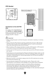
... CPU and heatsink/ cooler, Please refer to protect the CPU from the power outlet before booting your system. ∙ Overheating can tolerate overclocking. MSI will deal with Return Merchandise Authorization (RMA) requests if only the motherboard comes with the CPU before installing or removing the CPU. ∙ Please retain the CPU protective cap after installing the processor. Before attempting to overclock, please make sure the cooling fans work...
... CPU and heatsink/ cooler, Please refer to protect the CPU from the power outlet before booting your system. ∙ Overheating can tolerate overclocking. MSI will deal with Return Merchandise Authorization (RMA) requests if only the motherboard comes with the CPU before installing or removing the CPU. ∙ Please retain the CPU protective cap after installing the processor. Before attempting to overclock, please make sure the cooling fans work...
User Manual
Page 27
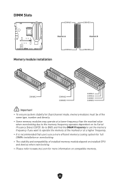
... that users use a more efficient memory cooling system for full DIMMs installation or overclocking. ∙ The stability and compatibility of the same type, number and density. ∙ Some memory modules may operate at a lower frequency than the marked value when overclocking due to www.msi.com for Dual channel mode, memory modules must be of installed memory module depend on installed CPU and devices when overclocking. ∙ Please refer to the memory frequency...
... that users use a more efficient memory cooling system for full DIMMs installation or overclocking. ∙ The stability and compatibility of the same type, number and density. ∙ Some memory modules may operate at a lower frequency than the marked value when overclocking due to www.msi.com for Dual channel mode, memory modules must be of installed memory module depend on installed CPU and devices when overclocking. ∙ Please refer to the memory frequency...

User Manual
Page 28
SATA_5~8: SATA 6Gb/s Connectors These connectors are SATA 6Gb/s interface ports. BAT1 PCI_E1~3: PCIe Expansion Slots PCI_E1: PCIe 4.0 x16 (From CPU) PCI_E2: PCIe 4.0 x1 (From B760 chipset) PCI_E3: PCIe 4.0 x1 (From B760 chipset) ⚠ Important ∙ If you install a large and heavy graphics card, you need to use a tool such as MSI Graphics Card Bolster to support its weight to the motherboard for any necessary additional hardware or software changes. However, it is recommended that...
SATA_5~8: SATA 6Gb/s Connectors These connectors are SATA 6Gb/s interface ports. BAT1 PCI_E1~3: PCIe Expansion Slots PCI_E1: PCIe 4.0 x16 (From CPU) PCI_E2: PCIe 4.0 x1 (From B760 chipset) PCI_E3: PCIe 4.0 x1 (From B760 chipset) ⚠ Important ∙ If you install a large and heavy graphics card, you need to use a tool such as MSI Graphics Card Bolster to support its weight to the motherboard for any necessary additional hardware or software changes. However, it is recommended that...

User Manual
Page 29
Lift up the M.2 Shield Frozr heatsink and remove it. 1 2 1 67 3. Skip this step, if you install 2280 SSD. 3 2260 2242 27 Secure the supplied M.2 standoff according to your SSD length. Loosen the screws of M.2 Shield Frozr heatsink. 2. M2_1~2: M.2 Slots (Key M) ⚠ Important ∙ Intel® RST only supports PCIe M.2 SSD with UEFI ROM. M2_1 M2_2 Installing M.2 module into M2_1 slot 1.
Lift up the M.2 Shield Frozr heatsink and remove it. 1 2 1 67 3. Skip this step, if you install 2280 SSD. 3 2260 2242 27 Secure the supplied M.2 standoff according to your SSD length. Loosen the screws of M.2 Shield Frozr heatsink. 2. M2_1~2: M.2 Slots (Key M) ⚠ Important ∙ Intel® RST only supports PCIe M.2 SSD with UEFI ROM. M2_1 M2_2 Installing M.2 module into M2_1 slot 1.
User Manual
Page 32
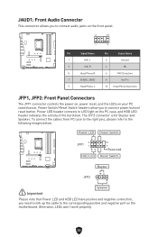
... PC case/chassis. Power LED header connects to the following images below. Otherwise, LEDs won't work properly. 30 To connect the cables from PC case to the right pins, please refer to LED light on the PC case, and HDD LED header indicates the activity of the hard disk. JAUD1: Front Audio Connector This connector allows you need to link up the cable to the corresponding positive and negative port on the motherboard. Power Switch/ Reset Switch headers allow you to connect power button/ reset button...
... PC case/chassis. Power LED header connects to the following images below. Otherwise, LEDs won't work properly. 30 To connect the cables from PC case to the right pins, please refer to LED light on the PC case, and HDD LED header indicates the activity of the hard disk. JAUD1: Front Audio Connector This connector allows you need to link up the cable to the corresponding positive and negative port on the motherboard. Power Switch/ Reset Switch headers allow you to connect power button/ reset button...
User Manual
Page 37
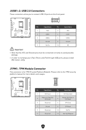
... USB ports, please install MSI Center utility. JUSB1~2: USB 2.0 Connectors These connectors allow you to connect USB 2.0 ports on the front panel. 2 10 1 9 Pin Signal Name Pin Signal Name 1 VCC 2 VCC 3 USB0- 4 USB1- 5 USB0+ 6 USB1+ 7 Ground 8 Ground 9 No Pin 10 NC ⚠ Important ∙ Note that the VCC and Ground pins must be connected correctly to avoid possible damage. ∙ In order to the TPM security platform manual...
... USB ports, please install MSI Center utility. JUSB1~2: USB 2.0 Connectors These connectors allow you to connect USB 2.0 ports on the front panel. 2 10 1 9 Pin Signal Name Pin Signal Name 1 VCC 2 VCC 3 USB0- 4 USB1- 5 USB0+ 6 USB1+ 7 Ground 8 Ground 9 No Pin 10 NC ⚠ Important ∙ Note that the VCC and Ground pins must be connected correctly to avoid possible damage. ∙ In order to the TPM security platform manual...
User Manual
Page 38
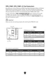
... Fan connector specifications Connector Default fan mode CPU_FAN1 Auto mode SYS_FAN1~2 DC mode Max. The auto mode fan connectors can be classified as PWM (Pulse Width Modulation) Mode or DC Mode. current 2A 1A Max. CPU_FAN1, SYS_FAN1~2: Fan Connectors Fan connectors can automatically detect PWM and DC mode. Uncheck the Smart Fan Mode, the fan will change according to your fan type. You can control fans in BIOS> HARDWARE MONITOR panel. Check the Smart Fan Mode, the fan speed will spin at maximum speed. ⚠ Important Make sure fans are working properly after switching...
... Fan connector specifications Connector Default fan mode CPU_FAN1 Auto mode SYS_FAN1~2 DC mode Max. The auto mode fan connectors can be classified as PWM (Pulse Width Modulation) Mode or DC Mode. current 2A 1A Max. CPU_FAN1, SYS_FAN1~2: Fan Connectors Fan connectors can automatically detect PWM and DC mode. Uncheck the Smart Fan Mode, the fan will change according to your fan type. You can control fans in BIOS> HARDWARE MONITOR panel. Check the Smart Fan Mode, the fan speed will spin at maximum speed. ⚠ Important Make sure fans are working properly after switching...
User Manual
Page 39
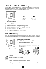
... Data (default) Clear CMOS/ Reset BIOS Resetting BIOS to chemical burns, perforation of soft tissue, can death. ∙ Severe burns can lead to default values 1. Replacing CMOS battery 1. Install the new CR2032 coin-cell battery with the + sign facing up. Use a jumper cap to save system configuration data. Remove the battery from JBAT1. 4. Plug the power cord and Power on the motherboard to short JBAT1 for about 5-10 seconds. 3. JBAT1: Clear CMOS (Reset BIOS) Jumper There is CMOS memory onboard that...
... Data (default) Clear CMOS/ Reset BIOS Resetting BIOS to chemical burns, perforation of soft tissue, can death. ∙ Severe burns can lead to default values 1. Replacing CMOS battery 1. Install the new CR2032 coin-cell battery with the + sign facing up. Use a jumper cap to save system configuration data. Remove the battery from JBAT1. 4. Plug the power cord and Power on the motherboard to short JBAT1 for about 5-10 seconds. 3. JBAT1: Clear CMOS (Reset BIOS) Jumper There is CMOS memory onboard that...
User Manual
Page 42
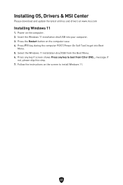
... POST (Power-On Self Test) to boot from the Boot Menu. 6. Select the Windows 11 installation disc/USB from CD or DVD... message. If not, please skip this step. 7. Insert the Windows 11 installation disc/USB into Boot Menu. 5. Press any key if screen shows Press any key to get into your computer. 3. Follow the instructions on the computer case. 4. Power on the computer. 2. Installing OS, Drivers & MSI Center Please download and update the latest utilities...
... POST (Power-On Self Test) to boot from the Boot Menu. 6. Select the Windows 11 installation disc/USB from CD or DVD... message. If not, please skip this step. 7. Insert the Windows 11 installation disc/USB into Boot Menu. 5. Press any key if screen shows Press any key to get into your computer. 3. Follow the instructions on the computer case. 4. Power on the computer. 2. Installing OS, Drivers & MSI Center Please download and update the latest utilities...
User Manual
Page 43
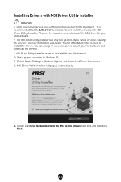
... supported by Windows 11. Installing Drivers with MSI Driver Utility Installer. Select Start > Settings > Windows Update, and then select Check for your motherboard. ∙ The MSI Driver Utility Installer will pop up your motherboard and download the drivers. ∙ MSI Driver Utility Installer needs to install the drivers. Please refer to www.msi.com to the MSI Terms of the MSI Center manual to be installed before installing drivers with MSI Driver Utility Installer ⚠ Important ∙ Some new network chips have read and agree to install the LAN driver for updates...
... supported by Windows 11. Installing Drivers with MSI Driver Utility Installer. Select Start > Settings > Windows Update, and then select Check for your motherboard. ∙ The MSI Driver Utility Installer will pop up your motherboard and download the drivers. ∙ MSI Driver Utility Installer needs to install the drivers. Please refer to www.msi.com to the MSI Terms of the MSI Center manual to be installed before installing drivers with MSI Driver Utility Installer ⚠ Important ∙ Some new network chips have read and agree to install the LAN driver for updates...
User Manual
Page 46
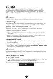
... enter Setup Menu, F11 to check the BIOS mode? 1. After entering the BIOS, you use CPU with integrated graphics for hard drive partitions larger than 2 TB. ∙ Supports more than 4 primary partitions with a GUID Partition Table (GPT). ∙ Supports unlimited number of partitions. ∙ Supports full capabilities of the screen. new devices may display a warning message There is compatible with UEFI (Unified Extensible Firmware Interface) architecture. the system will completely replace BIOS in this motherboard supports...
... enter Setup Menu, F11 to check the BIOS mode? 1. After entering the BIOS, you use CPU with integrated graphics for hard drive partitions larger than 2 TB. ∙ Supports more than 4 primary partitions with a GUID Partition Table (GPT). ∙ Supports unlimited number of partitions. ∙ Supports full capabilities of the screen. new devices may display a warning message There is compatible with UEFI (Unified Extensible Firmware Interface) architecture. the system will completely replace BIOS in this motherboard supports...
User Manual
Page 47
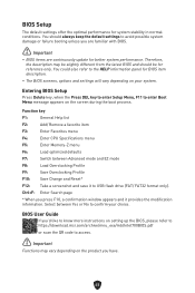
... failure booting unless you press F10, a confirmation window appears and it to USB flash drive (FAT/ FAT32 format only). Select between Advanced mode and EZ mode F8: Load Overclocking Profile F9: Save Overclocking Profile F10: Save Change and Reset* F12: Take a screenshot and save it provides the modification information. Function key F1: General Help list F2: Add/ Remove a favorite item F3: Enter Favorites menu F4: Enter CPU Specifications menu F5: Enter Memory-Z menu F6: Load optimized defaults...
... failure booting unless you press F10, a confirmation window appears and it to USB flash drive (FAT/ FAT32 format only). Select between Advanced mode and EZ mode F8: Load Overclocking Profile F9: Save Overclocking Profile F10: Save Change and Reset* F12: Take a screenshot and save it provides the modification information. Function key F1: General Help list F2: Add/ Remove a favorite item F3: Enter Favorites menu F4: Enter CPU Specifications menu F5: Enter Memory-Z menu F6: Load optimized defaults...

User Manual
Page 48
... M-FLASH button and click on Yes to start recovering BIOS. 6. Resetting BIOS You might need to restore the default BIOS setting to solve certain problems. There are several ways to reset BIOS: ∙ Go to BIOS and press F6 to load optimized defaults. ∙ Short the Clear CMOS jumper on the motherboard. ⚠ Important Be sure the computer is 100% completed, the system will reboot automatically. 46 Updating BIOS Updating BIOS with M-FLASH Before updating: Please download...
... M-FLASH button and click on Yes to start recovering BIOS. 6. Resetting BIOS You might need to restore the default BIOS setting to solve certain problems. There are several ways to reset BIOS: ∙ Go to BIOS and press F6 to load optimized defaults. ∙ Short the Clear CMOS jumper on the motherboard. ⚠ Important Be sure the computer is 100% completed, the system will reboot automatically. 46 Updating BIOS Updating BIOS with M-FLASH Before updating: Please download...
User Manual
Page 314
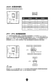
JAUD1 接腳 1 3 5 7 9 2 10 1 MIC L MIC R Head Phone R SENSE_SEND Head Phone L 9 接腳 訊號名稱 2 Ground 4 NC 6 MIC Detection 8 No Pin 10 Head Phone Detection JFP1、JFP2 JFP1 LED Power Switch/ Reset Switch Power LED LED 燈,HDD LED JFP2 Buzzer Speaker Power LED Power Switch JFP1 2 1 HDD LED 10 9 Reserved Reset Switch Buzzer JFP2 1 ⚠ 重要 Speaker 請注意 Power LED HDD LED LED 30
JAUD1 接腳 1 3 5 7 9 2 10 1 MIC L MIC R Head Phone R SENSE_SEND Head Phone L 9 接腳 訊號名稱 2 Ground 4 NC 6 MIC Detection 8 No Pin 10 Head Phone Detection JFP1、JFP2 JFP1 LED Power Switch/ Reset Switch Power LED LED 燈,HDD LED JFP2 Buzzer Speaker Power LED Power Switch JFP1 2 1 HDD LED 10 9 Reserved Reset Switch Buzzer JFP2 1 ⚠ 重要 Speaker 請注意 Power LED HDD LED LED 30
User Manual
Page 386
...., Ltd. Technical Support If a problem arises with your product at: http://register.msi.com Revision History ∙ Version 1.0, 2022/12, First release. ∙ Version 1.1, 2023/12, Update CPU spec. Alternatively, please try the following help resources for further guidance. ∙ Visit the MSI website for technical guide, BIOS updates, driver updates, and other marks and names mentioned may be obtained from the user guide, please contact...
...., Ltd. Technical Support If a problem arises with your product at: http://register.msi.com Revision History ∙ Version 1.0, 2022/12, First release. ∙ Version 1.1, 2023/12, Update CPU spec. Alternatively, please try the following help resources for further guidance. ∙ Visit the MSI website for technical guide, BIOS updates, driver updates, and other marks and names mentioned may be obtained from the user guide, please contact...


