
User Guide
Page 2
...iii Upgrade and Warranty iv Acquisition of Replaceable Parts iv Technical Support iv Green Product Features iv Environmental Policy v Chemical Substances Information v Battery Information v Safety Instructions vi CE Conformity viii FCC-B Radio Frequency Interference Statement viii WEEE Statement viii 1. System Operations 3-1 Power Management 3-2 Network Connection (Windows 7 3-4 Network Connection (Windows 8.x 3-7 System Recovery (Windows 7 3-10 System Recovery (Windows 8.x 3-20 Getting Started 2-1 Safety & Comfort Tips 2-2 Connecting Peripheral Devices 2-3 Hardware Setup...
...iii Upgrade and Warranty iv Acquisition of Replaceable Parts iv Technical Support iv Green Product Features iv Environmental Policy v Chemical Substances Information v Battery Information v Safety Instructions vi CE Conformity viii FCC-B Radio Frequency Interference Statement viii WEEE Statement viii 1. System Operations 3-1 Power Management 3-2 Network Connection (Windows 7 3-4 Network Connection (Windows 8.x 3-7 System Recovery (Windows 7 3-10 System Recovery (Windows 8.x 3-20 Getting Started 2-1 Safety & Comfort Tips 2-2 Connecting Peripheral Devices 2-3 Hardware Setup...
User Guide
Page 4
...://www.msi.com/support/ for technical iv guide, BIOS updates, driver updates and other information via http://www.msi.com/ support/ Green Product Features ◙ Reduced energy consumption during use and stand-by ◙ Limited use of substances harmful to the environment and health ◙ Easily dismantled and recycled ◙ Reduced use of purchase or local distributor. For any upgrade or replace service. Visit the MSI website...
...://www.msi.com/support/ for technical iv guide, BIOS updates, driver updates and other information via http://www.msi.com/ support/ Green Product Features ◙ Reduced energy consumption during use and stand-by ◙ Limited use of substances harmful to the environment and health ◙ Easily dismantled and recycled ◙ Reduced use of purchase or local distributor. For any upgrade or replace service. Visit the MSI website...
User Guide
Page 6
... unplug the AC power cord before setting it up. NOTE: The maximum operating temperature is used for a certain time to the power outlet. Safety Instructions ◙ Read the safety instructions carefully and thoroughly. ◙ All cautions and warnings on the enclosure is around 40OC. Keep this equipment on a reliable flat surface before installing any add-on card or module to...
... unplug the AC power cord before setting it up. NOTE: The maximum operating temperature is used for a certain time to the power outlet. Safety Instructions ◙ Read the safety instructions carefully and thoroughly. ◙ All cautions and warnings on the enclosure is around 40OC. Keep this equipment on a reliable flat surface before installing any add-on card or module to...

User Guide
Page 7
... service personnel: vii ◙ The power cord or plug is damaged. ◙ Liquid has penetrated into the opening that could damage or cause electrical shock. Place the power cord in particular Section 820.93, Grounding of Outer Conductive Shield of procedures other than those specified is prohibited. 2� Do not touch the lens inside the drive. Use of controls...
... service personnel: vii ◙ The power cord or plug is damaged. ◙ Liquid has penetrated into the opening that could damage or cause electrical shock. Place the power cord in particular Section 820.93, Grounding of Outer Conductive Shield of procedures other than those specified is prohibited. 2� Do not touch the lens inside the drive. Use of controls...
User Guide
Page 8
... been tested and found to comply with Part 15 of the measures listed below: ■ Reorient or relocate the receiving antenna. ■ Increase the separation between the equipment and receiver. ■ Connect the equipment into an outlet on August 13, 2005, products of "electrical and electronic equipment" cannot be used in accordance with the instruction manual, may...
... been tested and found to comply with Part 15 of the measures listed below: ■ Reorient or relocate the receiving antenna. ■ Increase the separation between the equipment and receiver. ■ Connect the equipment into an outlet on August 13, 2005, products of "electrical and electronic equipment" cannot be used in accordance with the instruction manual, may...
User Guide
Page 10
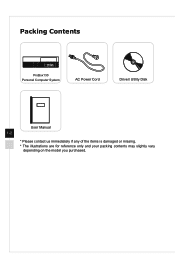
Packing Contents ProBox130 Personal Computer System AC Power Cord Driver/ Utility Disk User Manual 1-2 * Please contact us immediately if any of the items is damaged or missing. * The illustrations are for reference only and your packing contents may slightly vary depending on the model you purchased.
Packing Contents ProBox130 Personal Computer System AC Power Cord Driver/ Utility Disk User Manual 1-2 * Please contact us immediately if any of the items is damaged or missing. * The illustrations are for reference only and your packing contents may slightly vary depending on the model you purchased.

User Guide
Page 11
... supports up from power saving mode. In terms of power saving, the LED blinks in S3 (Suspend to RAM) mode and goes off when the system is shut down. Pressing the system power button will wake the system up to 480Mbit/s (Hi-Speed) data transfer rate. 2 Microphone Jack This connector is provided for microphones. 3 Headphone Jack This connector is provided for attaching USB devices such as keyboard, mouse...
... supports up from power saving mode. In terms of power saving, the LED blinks in S3 (Suspend to RAM) mode and goes off when the system is shut down. Pressing the system power button will wake the system up to 480Mbit/s (Hi-Speed) data transfer rate. 2 Microphone Jack This connector is provided for microphones. 3 Headphone Jack This connector is provided for attaching USB devices such as keyboard, mouse...

User Guide
Page 12
Important High-speed devices are suggested to be plugged into the USB 2.0 ports. 1-4 It flashes when the system is accessing data on the HDD and remains off when no disk activity is detected. 6 Power Button Press the power button to turn the system on and off. 7 Optical Disk Drive (Optional) A DVD Super-Multi drive is integrated for USB 3.0 ports whereas low-speed devices, such as mouse or keyboard, are recommended for your home entertainment. 5 Hard Disk Drive LED This indicator shows the activity status of the HDD.
Important High-speed devices are suggested to be plugged into the USB 2.0 ports. 1-4 It flashes when the system is accessing data on the HDD and remains off when no disk activity is detected. 6 Power Button Press the power button to turn the system on and off. 7 Optical Disk Drive (Optional) A DVD Super-Multi drive is integrated for USB 3.0 ports whereas low-speed devices, such as mouse or keyboard, are recommended for your home entertainment. 5 Hard Disk Drive LED This indicator shows the activity status of the HDD.

User Guide
Page 14
... devices. Mic (Pink) is used for speakers or headphones. LAN link is not established. You can connect a network cable to the Local Area Network (LAN). 7 USB 2.0 Port The USB (Universal Serial Bus) port is for attaching USB devices such as keyboard, mouse, or other audio devices. Yellow Green/ Orange 1-6 LED Color LED State Left Yellow Off On (steady state) On (blinking) Right Green Off On Orange On Condition LAN link is established. Do not cover...
... devices. Mic (Pink) is used for speakers or headphones. LAN link is not established. You can connect a network cable to the Local Area Network (LAN). 7 USB 2.0 Port The USB (Universal Serial Bus) port is for attaching USB devices such as keyboard, mouse, or other audio devices. Yellow Green/ Orange 1-6 LED Color LED State Left Yellow Off On (steady state) On (blinking) Right Green Off On Orange On Condition LAN link is established. Do not cover...

User Guide
Page 16
... supplies power to your system. 10 LAN Jack The standard RJ-45 LAN jack is provided for connection to prevent the equipment from overheating. 6 VGA Port The DB15-pin female port is provided for monitor. 7 USB 2.0 Port The USB (Universal Serial Bus) port is for attaching USB devices such as keyboard, mouse, or other audio devices. Line-Out (Green) is used for speakers or headphones. It supports up to it. 1-8 Yellow Green/ Orange LED Color LED...
... supplies power to your system. 10 LAN Jack The standard RJ-45 LAN jack is provided for connection to prevent the equipment from overheating. 6 VGA Port The DB15-pin female port is provided for monitor. 7 USB 2.0 Port The USB (Universal Serial Bus) port is for attaching USB devices such as keyboard, mouse, or other audio devices. Line-Out (Green) is used for speakers or headphones. It supports up to it. 1-8 Yellow Green/ Orange LED Color LED...
User Guide
Page 17
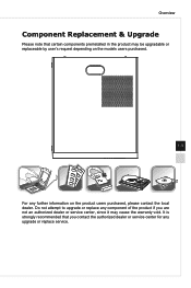
Do not attempt to upgrade or replace any component of the product if you contact the authorized dealer or service center for any further information on the models users purchased. 1-9 For any upgrade or replace service. It is strongly recommended that certain components preinstalled in the product may cause the warranty void. Overview Component Replacement & Upgrade Please note that you are not an authorized dealer or service center, since it may be upgradable or replaceable by user's request depending on the product users purchased, please contact the local dealer.
Do not attempt to upgrade or replace any component of the product if you contact the authorized dealer or service center for any further information on the models users purchased. 1-9 For any upgrade or replace service. It is strongly recommended that certain components preinstalled in the product may cause the warranty void. Overview Component Replacement & Upgrade Please note that you are not an authorized dealer or service center, since it may be upgradable or replaceable by user's request depending on the product users purchased, please contact the local dealer.

User Guide
Page 22
...; Connecting VGA-Out & HDMI-Out Devices This ProBox130 Personal Computer System provides a VGA port and an HDMI port for connection to carry analog video signals along with digital clock and data. VGA connectors and their associated cabling are both powered off, and then connect the cable of the device to the VGA/ HDMI port of your ProBox130 Personal Computer System. 2-4 HDMI (High Definition Multimedia Interface) is a graphics display system for PCs, displays and consumer electronics devices that supports...
...; Connecting VGA-Out & HDMI-Out Devices This ProBox130 Personal Computer System provides a VGA port and an HDMI port for connection to carry analog video signals along with digital clock and data. VGA connectors and their associated cabling are both powered off, and then connect the cable of the device to the VGA/ HDMI port of your ProBox130 Personal Computer System. 2-4 HDMI (High Definition Multimedia Interface) is a graphics display system for PCs, displays and consumer electronics devices that supports...

User Guide
Page 24
... device first if necessary, and then connect the device to add the new device. 2-6 This ProBox130 Personal Computer System is capable of auto detecting the USB devices installed, and if there is no detection of the devices, please manually enable the USB devices by going to Start Menu / Control Panel / Add Hardware to the ProBox130 Personal Computer System. and etc. To connect these devices, install the drivers for connecting various USB devices, such as mouse, keyboard, digital camera, webcam, printer, external optical storage device...
... device first if necessary, and then connect the device to add the new device. 2-6 This ProBox130 Personal Computer System is capable of auto detecting the USB devices installed, and if there is no detection of the devices, please manually enable the USB devices by going to Start Menu / Control Panel / Add Hardware to the ProBox130 Personal Computer System. and etc. To connect these devices, install the drivers for connecting various USB devices, such as mouse, keyboard, digital camera, webcam, printer, external optical storage device...

User Guide
Page 30
... settings by clicking [Change plan settings]. Select a power plan that suits your personal needs. To be energy efficient, turn off your display or set your PC to sleep mode after a period of user inactivity. Power Management in Windows 7 ■ [Power Options] in Windows OS allow you to control the power management features of your display, hard drive, and battery. You may also fine-tune the settings by clicking [Change plan settings]. ■ The Shut Down Computer menu...
... settings by clicking [Change plan settings]. Select a power plan that suits your personal needs. To be energy efficient, turn off your display or set your PC to sleep mode after a period of user inactivity. Power Management in Windows 7 ■ [Power Options] in Windows OS allow you to control the power management features of your display, hard drive, and battery. You may also fine-tune the settings by clicking [Change plan settings]. ■ The Shut Down Computer menu...

User Guide
Page 31
... power button, ■ the network (Wake On LAN), ■ the mouse, 3-3 ■ the keyboard. System Operations ■ The Shut Down Computer menu presents the options of Sleep (S3/S4) & Shut Down (S5) for rapid and easy management of your PC's energy consumption. ■ Always disconnect the AC power cord or switch the wall socket off the display after 15 minutes ■ Initiate Sleep after a period of user...
... power button, ■ the network (Wake On LAN), ■ the mouse, 3-3 ■ the keyboard. System Operations ■ The Shut Down Computer menu presents the options of Sleep (S3/S4) & Shut Down (S5) for rapid and easy management of your PC's energy consumption. ■ Always disconnect the AC power cord or switch the wall socket off the display after 15 minutes ■ Initiate Sleep after a period of user...

User Guide
Page 33
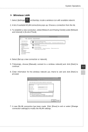
Choose a connection from the list or click [Open Network and Sharing Center] to the Internet] under [Network and Internet]. 3-5 3. A list of available WLAN connections pops up. Select [Connect to establish a new connection. Go to connect using a wireless router or a wireless network. 4. Select [Wireless] to [Start] > [Control Panel]. 2. System Operations Wireless LAN 1.
Choose a connection from the list or click [Open Network and Sharing Center] to the Internet] under [Network and Internet]. 3-5 3. A list of available WLAN connections pops up. Select [Connect to establish a new connection. Go to connect using a wireless router or a wireless network. 4. Select [Wireless] to [Start] > [Control Panel]. 2. System Operations Wireless LAN 1.
User Guide
Page 34
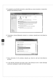
Followingly, choose [Manually connect to a wireless network] and click [Next] to proceed. 8. A new WLAN connection has been made. Enter information for the wireless network you intend to add and click [Next] to continue. 3-6 7. Click [Close] to exit or select [Change connection settings] to modify the WLAN settings. 5. To establish a new WLAN connection, select [Set up a new connection or network] in [Network and Sharing Center]. 6.
Followingly, choose [Manually connect to a wireless network] and click [Next] to proceed. 8. A new WLAN connection has been made. Enter information for the wireless network you intend to add and click [Next] to continue. 3-6 7. Click [Close] to exit or select [Change connection settings] to modify the WLAN settings. 5. To establish a new WLAN connection, select [Set up a new connection or network] in [Network and Sharing Center]. 6.

User Guide
Page 35
Select [Set up a new connection or network]. System Operations Network Connection (Windows 8.x) Wired LAN 1. Go to [Start] > [Control Panel]. 2. Select [View network status and tasks] under [Network and Internet]. 3-7 3. To establish a new connection, select [Network and Sharing Center]. 4.
Select [Set up a new connection or network]. System Operations Network Connection (Windows 8.x) Wired LAN 1. Go to [Start] > [Control Panel]. 2. Select [View network status and tasks] under [Network and Internet]. 3-7 3. To establish a new connection, select [Network and Sharing Center]. 4.
User Guide
Page 37
...new WLAN connection has been made. System Operations Wireless LAN 1. A list of available WLAN connections pops up a new connection or network]. 5. Followingly, choose [Manually connect to a wireless network] and click [Next] to proceed. 7. Choose a connection from the list. 3. Enter information for the wireless network you intend to add and click [Next] to continue. 3-9 6. To establish a new connection, select [Network and Sharing Center] under [Network and Internet] in [Control Panel]. 4. Select [Set up . Click [Close] to exit or select [Change connection settings...
...new WLAN connection has been made. System Operations Wireless LAN 1. A list of available WLAN connections pops up a new connection or network]. 5. Followingly, choose [Manually connect to a wireless network] and click [Next] to proceed. 7. Choose a connection from the list. 3. Enter information for the wireless network you intend to add and click [Next] to continue. 3-9 6. To establish a new connection, select [Network and Sharing Center] under [Network and Internet] in [Control Panel]. 4. Select [Set up . Click [Close] to exit or select [Change connection settings...
User Guide
Page 38
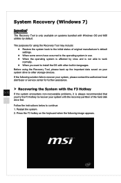
... the system encounters non-recoverable problems, it is always recommended that you want to install the OS with other storage devices. If the following image appears. Before using the Recovery Tool may include: ■ Restore the system back to the initial status of the hard disk drive first. System Recovery (Windows 7) Important The Recovery Tool is not able to work normally. ■ When you...
... the system encounters non-recoverable problems, it is always recommended that you want to install the OS with other storage devices. If the following image appears. Before using the Recovery Tool may include: ■ Restore the system back to the initial status of the hard disk drive first. System Recovery (Windows 7) Important The Recovery Tool is not able to work normally. ■ When you...


