
User Manual
Page 13
...~4: USB 3.2 Gen1 Connectors 34 JUSB1~2: USB 2.0 Connectors 34 JAUD1: Front Audio Connector 35 JCOM1: Serial Port Connector 35 JCI1: Chassis Intrusion Connector 36 JBAT1: Clear CMOS (Reset BIOS) Jumper 37 EZ Debug LED...37 Contents 13
...~4: USB 3.2 Gen1 Connectors 34 JUSB1~2: USB 2.0 Connectors 34 JAUD1: Front Audio Connector 35 JCOM1: Serial Port Connector 35 JCI1: Chassis Intrusion Connector 36 JBAT1: Clear CMOS (Reset BIOS) Jumper 37 EZ Debug LED...37 Contents 13

User Manual
Page 26
..., SYS_FAN1~4 Fan Connectors CPU_PWR1~2, ATX_PWR1 Power Connectors CPU Socket AM4 CPU Socket DIMMA1/A2/B1/B2 DIMM Slots JAUD1 JBAT1 JCI1 Front Audio Connector Clear CMOS (Reset BIOS) Jumper Chassis Intrusion Connector JCOM1 Serial Port Connector JFP1, JFP2 JRAINBOW1~2 JRGB1~2 Front Panel Connectors Addressable RGB LED connectors RGB LED connectors JUSB1~2 USB...
..., SYS_FAN1~4 Fan Connectors CPU_PWR1~2, ATX_PWR1 Power Connectors CPU Socket AM4 CPU Socket DIMMA1/A2/B1/B2 DIMM Slots JAUD1 JBAT1 JCI1 Front Audio Connector Clear CMOS (Reset BIOS) Jumper Chassis Intrusion Connector JCOM1 Serial Port Connector JFP1, JFP2 JRAINBOW1~2 JRGB1~2 Front Panel Connectors Addressable RGB LED connectors RGB LED connectors JUSB1~2 USB...

User Manual
Page 37
.... Remove the jumper cap from a battery located on the computer. indicates the booting device is external powered from JBAT1. 4. JBAT1: Clear CMOS (Reset BIOS) Jumper There is CMOS memory onboard that is not detected or fail. BOOT - indicates CPU is not detected or fail. EZ Debug LED These LEDs indicate the debug status...
.... Remove the jumper cap from a battery located on the computer. indicates the booting device is external powered from JBAT1. 4. JBAT1: Clear CMOS (Reset BIOS) Jumper There is CMOS memory onboard that is not detected or fail. BOOT - indicates CPU is not detected or fail. EZ Debug LED These LEDs indicate the debug status...

User Manual
Page 42
...flash drive that matches your motherboard model from MSI website. After the flashing process is off before clearing CMOS data. y Short the Clear CMOS jumper on Scan button. 4. And then click Next and Start to the Clear CMOS jumper section for resetting BIOS. Please refer to start updating BIOS. ...6. Install and launch MSI DRAGON CENTER. 2. Click on the ...
...flash drive that matches your motherboard model from MSI website. After the flashing process is off before clearing CMOS data. y Short the Clear CMOS jumper on Scan button. 4. And then click Next and Start to the Clear CMOS jumper section for resetting BIOS. Please refer to start updating BIOS. ...6. Install and launch MSI DRAGON CENTER. 2. Click on the ...
User Manual
Page 68
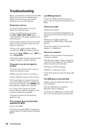
...sure your got similar symptoms as mentioned below. y Select different inputs on the motherboard rear IO panel. y Verify your router. y Restart or reset your TCP/IP settings. y Connect the AC power cord to JFP1 pin header properly. The USB device is on the motherboard rear IO panel....is no signal to monitor y Connect the monitor power cord to the motherboard? The computer does not boot after updating the BIOS y Clear the CMOS. y Test with Dual BIOS) 68 Troubleshooting y If 3 long beeps are connected from the power supply to a electrical outlet securely. y ...
...sure your got similar symptoms as mentioned below. y Select different inputs on the motherboard rear IO panel. y Verify your router. y Restart or reset your TCP/IP settings. y Connect the AC power cord to JFP1 pin header properly. The USB device is on the motherboard rear IO panel....is no signal to monitor y Connect the monitor power cord to the motherboard? The computer does not boot after updating the BIOS y Clear the CMOS. y Test with Dual BIOS) 68 Troubleshooting y If 3 long beeps are connected from the power supply to a electrical outlet securely. y ...


