User Manual
Page 13
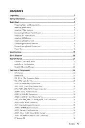
...2 Quick Start ...3 Preparing Tools and Components 3 Installing a Processor 4 Installing DDR4 memory 5 Connecting the Front Panel Header 6 Installing the Motherboard 7 Installing SATA Drives 8 Installing a Graphics Card 9 Connecting Peripheral Devices 10 Connecting the Power Connectors 11 Power On...12 Specifications...15 Block Diagram ...20 Rear I/O Panel ...21 LAN Port LED Status Table 21 Audio Ports Configuration 21 Realtek HD Audio Manager 22 Overview of Components 24 CPU Socket ...26 DIMM Slots...27 PCI_E1~6: PCIe Expansion Slots 28 M2_1: M.2 Slot (Key M 29 SATA1~6: SATA 6Gb...
...2 Quick Start ...3 Preparing Tools and Components 3 Installing a Processor 4 Installing DDR4 memory 5 Connecting the Front Panel Header 6 Installing the Motherboard 7 Installing SATA Drives 8 Installing a Graphics Card 9 Connecting Peripheral Devices 10 Connecting the Power Connectors 11 Power On...12 Specifications...15 Block Diagram ...20 Rear I/O Panel ...21 LAN Port LED Status Table 21 Audio Ports Configuration 21 Realtek HD Audio Manager 22 Overview of Components 24 CPU Socket ...26 DIMM Slots...27 PCI_E1~6: PCIe Expansion Slots 28 M2_1: M.2 Slot (Key M 29 SATA1~6: SATA 6Gb...
User Manual
Page 14
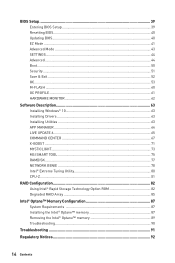
... HARDWARE MONITOR 62 Software Description 63 Installing Windows® 10 63 Installing Drivers 63 Installing Utilities 63 APP MANAGER ...64 LIVE UPDATE 6...65 COMMAND CENTER 67 X-BOOST ...71 MYSTICLIGHT...73 MSI SMART TOOL 75 RAMDISK...77 NETWORK GENIE 78 Intel® Extreme Tuning Utility 80 CPU-Z...81 RAID Configuration 82 Using Intel® Rapid Storage Technology Option ROM 82 Degraded RAID Array 85 Intel® Optane™ Memory Configuration 87 System Requirements 87 Installing the...
... HARDWARE MONITOR 62 Software Description 63 Installing Windows® 10 63 Installing Drivers 63 Installing Utilities 63 APP MANAGER ...64 LIVE UPDATE 6...65 COMMAND CENTER 67 X-BOOST ...71 MYSTICLIGHT...73 MSI SMART TOOL 75 RAMDISK...77 NETWORK GENIE 78 Intel® Extreme Tuning Utility 80 CPU-Z...81 RAID Configuration 82 Using Intel® Rapid Storage Technology Option ROM 82 Degraded RAID Array 85 Intel® Optane™ Memory Configuration 87 System Requirements 87 Installing the...

User Manual
Page 15
Specifications CPU Chipset Memory Expansion Slots Onboard Graphics y Supports 8th Gen Intel® Core™ processors, and Intel® Pentium® and Celeron® processors for Socket LGA1151 Intel® Z370 Chipset y 4x DDR4 memory slots, support up to PCIe 3.0 x4 and SATA 6Gb/s ƒ Supports 2242/ 2260 /2280/ 22110 storage devices ƒ Support PCIe 3.0 x4 NVMe U.2 SSD with Turbo U.2 Host Card** ƒ Intel® Optane™ Memory Ready*** * The SATA1 port will be unavailable when M.2 SATA SSD has...
Specifications CPU Chipset Memory Expansion Slots Onboard Graphics y Supports 8th Gen Intel® Core™ processors, and Intel® Pentium® and Celeron® processors for Socket LGA1151 Intel® Z370 Chipset y 4x DDR4 memory slots, support up to PCIe 3.0 x4 and SATA 6Gb/s ƒ Supports 2242/ 2260 /2280/ 22110 storage devices ƒ Support PCIe 3.0 x4 NVMe U.2 SSD with Turbo U.2 Host Card** ƒ Intel® Optane™ Memory Ready*** * The SATA1 port will be unavailable when M.2 SATA SSD has...
User Manual
Page 17
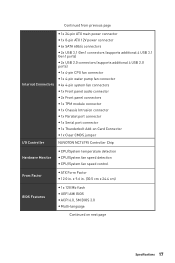
...8-pin ATX 12V power connector y 6x SATA 6Gb/s connectors y 2x USB 3.1 Gen1 connectors (supports additional 4 USB 3.1 Gen1 ports) y 2x USB 2.0 connectors (supports additional 4 USB 2.0 ports) y 1x 4-pin CPU fan connector y 1x 4-pin water pump fan connector y 4x 4-pin system fan connectors y 1x Front panel audio connector y 2x Front panel connectors y 1x TPM module connector y 1x Chassis Intrusion connector y 1x Parallel port connector y 1x Serial port connector y 1x Thunderbolt Add-on Card Connector y 1x Clear CMOS jumper I/O Controller NUVOTON NCT6795 Controller Chip Hardware Monitor y CPU...
...8-pin ATX 12V power connector y 6x SATA 6Gb/s connectors y 2x USB 3.1 Gen1 connectors (supports additional 4 USB 3.1 Gen1 ports) y 2x USB 2.0 connectors (supports additional 4 USB 2.0 ports) y 1x 4-pin CPU fan connector y 1x 4-pin water pump fan connector y 4x 4-pin system fan connectors y 1x Front panel audio connector y 2x Front panel connectors y 1x TPM module connector y 1x Chassis Intrusion connector y 1x Parallel port connector y 1x Serial port connector y 1x Thunderbolt Add-on Card Connector y 1x Clear CMOS jumper I/O Controller NUVOTON NCT6795 Controller Chip Hardware Monitor y CPU...

User Manual
Page 40
y Short the Clear CMOS jumper on Scan button. 4. Updating BIOS Updating BIOS with Live Update 6 Before updating: Make sure the LAN driver is already installed and the Internet connection is 100% completed, the system will reboot automatically. Insert the USB flash drive that matches your motherboard model from MSI website. Install and launch MSI LIVE UPDATE 6. 2. Click on the motherboard. Click Next and choose In Windows mode. After the flashing process is set properly. Select a BIOS file to load optimized defaults. After the flashing process...
y Short the Clear CMOS jumper on Scan button. 4. Updating BIOS Updating BIOS with Live Update 6 Before updating: Make sure the LAN driver is already installed and the Internet connection is 100% completed, the system will reboot automatically. Insert the USB flash drive that matches your motherboard model from MSI website. Install and launch MSI LIVE UPDATE 6. 2. Click on the motherboard. Click Next and choose In Windows mode. After the flashing process is set properly. Select a BIOS file to load optimized defaults. After the flashing process...

User Manual
Page 41
... to enable/ disable the X.M.P. (Extreme Memory Profile). click on the inner circle to right. It allows you to find the item listing. To configure the advanced BIOS settings, please enter the Advanced Mode by BIOS item name, enter the item name to select the language of BIOS setup. The boot priority from high to low is installed. y Screenshot - click on this tab or the F7 key to USB flash drive...
... to enable/ disable the X.M.P. (Extreme Memory Profile). click on the inner circle to right. It allows you to find the item listing. To configure the advanced BIOS settings, please enter the Advanced Mode by BIOS item name, enter the item name to select the language of BIOS setup. The boot priority from high to low is installed. y Screenshot - click on this tab or the F7 key to USB flash drive...
User Manual
Page 42
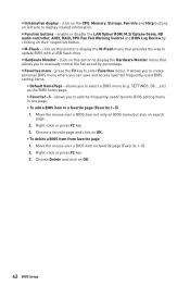
... respective button. enable or disable the LAN Option ROM, M.2/ Optane Genie, HD audio controller, AHCI, RAID, CPU Fan Fail Warning Control and BIOS Log Review by percentage. Right-click or press F2 key. 3. click on left side to manually control the fan speed by clicking on OK. ƒ To delete a BIOS item from favorite page 1. click on the CPU, Memory, Storage, Fan Info and Help buttons on this button to display the M-Flash menu that allows you to enter Favorites menu. y Hardware Monitor - SETTINGS...
... respective button. enable or disable the LAN Option ROM, M.2/ Optane Genie, HD audio controller, AHCI, RAID, CPU Fan Fail Warning Control and BIOS Log Review by percentage. Right-click or press F2 key. 3. click on left side to manually control the fan speed by clicking on OK. ƒ To delete a BIOS item from favorite page 1. click on the CPU, Memory, Storage, Fan Info and Help buttons on this button to display the M-Flash menu that allows you to enter Favorites menu. y Hardware Monitor - SETTINGS...
User Manual
Page 45
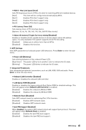
... disables the onboard LAN controller. Press Enter to indicate the S3 state. f ACPI Settings Sets ACPI parameters of PCIe x16 slots for matching different installed devices. [Auto] This item will appear when Network Stack is only available if the system supports 64-bit PCI decoding. [Enabled] Allows you to utilize more than 4x GPUs. [Disabled] Disables this function. fPower LED [Blinking] Sets shining behaviors of PCI interface device. [Options: 32, 64, 96, 128, 160, 192, 224, 248 PCI Bus clocks...
... disables the onboard LAN controller. Press Enter to indicate the S3 state. f ACPI Settings Sets ACPI parameters of PCIe x16 slots for matching different installed devices. [Auto] This item will appear when Network Stack is only available if the system supports 64-bit PCI decoding. [Enabled] Allows you to utilize more than 4x GPUs. [Disabled] Disables this function. fPower LED [Blinking] Sets shining behaviors of PCI interface device. [Options: 32, 64, 96, 128, 160, 192, 224, 248 PCI Bus clocks...
User Manual
Page 46
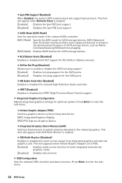
... hot-plugging. [RAID Mode] Enables RAID function for optimum system. This item appears when Initiate Graphic Adapter set to enter the submenu. 46 BIOS Setup fSATA Mode [AHCI Mode] Sets the operation mode of system memory allocated to enter the sub-menu. fHD Audio Controller [Enabled] Enables or disables the onboard High Definition Audio controller. This item will appear when IGD Multi-Monitor is enabled. [Enabled] Enables the Ipv6 PXE boot support. [Disabled] Disables the Ipv6 PXE boot support. fIpv6 PXE Support [Enabled] When Enabled, the system UEFI network stack...
... hot-plugging. [RAID Mode] Enables RAID function for optimum system. This item appears when Initiate Graphic Adapter set to enter the submenu. 46 BIOS Setup fSATA Mode [AHCI Mode] Sets the operation mode of system memory allocated to enter the sub-menu. fHD Audio Controller [Enabled] Enables or disables the onboard High Definition Audio controller. This item will appear when IGD Multi-Monitor is enabled. [Enabled] Enables the Ipv6 PXE boot support. [Disabled] Disables the Ipv6 PXE boot support. fIpv6 PXE Support [Enabled] When Enabled, the system UEFI network stack...

User Manual
Page 48
... power. [Power On] Boot up booting time. This item will switch to UEFI mode to enter BIOS setup if needed. fErP Ready [Disabled] Enables or disables the system power consumption according to ErP regulation. [Enabled] Optimize the system power consumption according to accelerate system boot time. [Disabled] Disables the Fast Boot configuration. 48 BIOS Setup fWindows 10 WHQL Support [Disabled] Enables the supports for Windows 10 or disables for other operating systems. Before enabling this function. Important When MSI Fast Boot is disabled. [Enabled] Enables...
... power. [Power On] Boot up booting time. This item will switch to UEFI mode to enter BIOS setup if needed. fErP Ready [Disabled] Enables or disables the system power consumption according to ErP regulation. [Enabled] Optimize the system power consumption according to accelerate system boot time. [Disabled] Disables the Fast Boot configuration. 48 BIOS Setup fWindows 10 WHQL Support [Disabled] Enables the supports for Windows 10 or disables for other operating systems. Before enabling this function. Important When MSI Fast Boot is disabled. [Enabled] Enables...

User Manual
Page 49
... (using the + and - keys to enter the sub-menu. fSecure Boot Mode [Standard] Selects the secure boot mode. Press Enter to enter the sub-menu. This sub-menu will appear when Secure Boot Mode sets to boot up events will automatically load the secure keys from the power saving modes when activity or input signal of installed PCI-E expansion cards, integrated LAN controllers or USB devices which are supported by OS. fKey Management Manages the secure boot keys. Press to enter...
... (using the + and - keys to enter the sub-menu. fSecure Boot Mode [Standard] Selects the secure boot mode. Press Enter to enter the sub-menu. This sub-menu will appear when Secure Boot Mode sets to boot up events will automatically load the secure keys from the power saving modes when activity or input signal of installed PCI-E expansion cards, integrated LAN controllers or USB devices which are supported by OS. fKey Management Manages the secure boot keys. Press to enter...
User Manual
Page 50
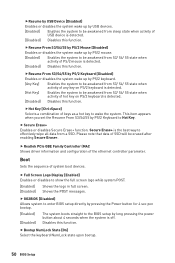
... keyboard NumLock state upon bootup. 50 BIOS Setup Secure Erase+ is detected. [Disabled] Disables this function. f Realtek PCIe GBE Family Controller (MAC Shows driver information and configuration of system boot devices. Boot Sets the sequence of the ethernet controller parameter. f Full Screen Logo Display [Enabled] Enables or disables to be awakened from sleep state when activity of USB device is the best way to Hot Key. fResume by USB Device [Disabled] Enables or disables the system wake up by USB devices. [Enabled] Enables...
... keyboard NumLock state upon bootup. 50 BIOS Setup Secure Erase+ is detected. [Disabled] Disables this function. f Realtek PCIe GBE Family Controller (MAC Shows driver information and configuration of system boot devices. Boot Sets the sequence of the ethernet controller parameter. f Full Screen Logo Display [Enabled] Enables or disables to be awakened from sleep state when activity of USB device is the best way to Hot Key. fResume by USB Device [Disabled] Enables or disables the system wake up by USB devices. [Enabled] Enables...
User Manual
Page 52
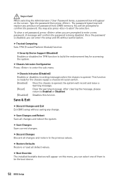
... password is opened , the system will be the boot device. 52 BIOS Setup A message will replace any change. fSecurity Device Support [Disabled] Enables or disables the TPM function to enter the sub-menu. fChassis Intrusion [Disabled] Enables or disables recording messages when the chassis is being disabled. f Save Changes and Reboot Save all default values. f Restore Defaults Restore or load all changes and reboot the system. f Chassis Intrusion Configuration Press to build the endorsement key for the chassis...
... password is opened , the system will be the boot device. 52 BIOS Setup A message will replace any change. fSecurity Device Support [Disabled] Enables or disables the TPM function to enter the sub-menu. fChassis Intrusion [Disabled] Enables or disables recording messages when the chassis is being disabled. f Save Changes and Reboot Save all default values. f Restore Defaults Restore or load all changes and reboot the system. f Chassis Intrusion Configuration Press to build the endorsement key for the chassis...
User Manual
Page 54
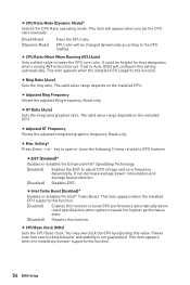
... appears when the installed processor supports this value. f Ring Ratio [Auto] Sets the ring ratio. Read-only. f Adjusted GT Frequency Shows the adjusted integrated graphics frequency. You may overclock the CPU by adjusting this function. 54 BIOS Setup f GT Ratio [Auto] Sets the integrated graphics ratio. Read-only. fIntel Turbo Boost [Enabled]* Enables or disables the Intel® Turbo Boost. It could be changed dynamically according to Auto, BIOS will be...
... appears when the installed processor supports this value. f Ring Ratio [Auto] Sets the ring ratio. Read-only. f Adjusted GT Frequency Shows the adjusted integrated graphics frequency. You may overclock the CPU by adjusting this function. 54 BIOS Setup f GT Ratio [Auto] Sets the integrated graphics ratio. Read-only. fIntel Turbo Boost [Enabled]* Enables or disables the Intel® Turbo Boost. It could be changed dynamically according to Auto, BIOS will be...

User Manual
Page 55
... for each/ all memory channel. Controls the digital powers related to enter the sub-menu. This item will be available when the memory modules that supports this setting automatically. f DRAM Frequency [Auto] Sets the DRAM frequency. User can set to enter the sub-menu. If it occurs, please clear the CMOS data and restore the default settings. (Refer to the Clear CMOS jumper/ button section to clear the CMOS data, and enter the BIOS to load the default settings.) f Memory Fast Boot [Auto]* Enables or disables the initiation and...
... for each/ all memory channel. Controls the digital powers related to enter the sub-menu. This item will be available when the memory modules that supports this setting automatically. f DRAM Frequency [Auto] Sets the DRAM frequency. User can set to enter the sub-menu. If it occurs, please clear the CMOS data and restore the default settings. (Refer to the Clear CMOS jumper/ button section to clear the CMOS data, and enter the BIOS to load the default settings.) f Memory Fast Boot [Auto]* Enables or disables the initiation and...
User Manual
Page 58
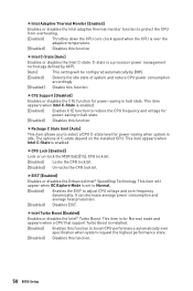
... Mode is set to Normal. [Enabled] Enables the EIST to boost CPU performance automatically over the adaptive temperature. [Disabled] Disables this function. This item is for power-saving in halt state. [Disabled] Disables this function. 58 BIOS Setup fIntel C-State [Auto] Enables or disables the Intel C-state. fC1E Support [Disabled] Enables or disables the C1E function for Normal mode and appears when a CPU that support Turbo Boost is installed. [Enabled] Enables this function to adjust CPU voltage and core frequency...
... Mode is set to Normal. [Enabled] Enables the EIST to boost CPU performance automatically over the adaptive temperature. [Disabled] Disables this function. This item is for power-saving in halt state. [Disabled] Disables this function. 58 BIOS Setup fIntel C-State [Auto] Enables or disables the Intel C-state. fC1E Support [Disabled] Enables or disables the C1E function for Normal mode and appears when a CPU that support Turbo Boost is installed. [Enabled] Enables this function to adjust CPU voltage and core frequency...
User Manual
Page 60
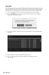
..., the system will appear after rebooting. 4. The system will enter the flash mode and a file selection menu will reboot automatically. 60 BIOS Setup Select a BIOS file to update BIOS. 1. Click on Yes to update BIOS with a USB flash drive. Please down-load the latest BIOS file that contains the update file into your USB flash drive. Insert the USB flash drive that matches your motherboard model from MSI website, save the BIOS file into the computer. 2. And then follow the steps below...
..., the system will appear after rebooting. 4. The system will enter the flash mode and a file selection menu will reboot automatically. 60 BIOS Setup Select a BIOS file to update BIOS. 1. Click on Yes to update BIOS with a USB flash drive. Please down-load the latest BIOS file that contains the update file into your USB flash drive. Insert the USB flash drive that matches your motherboard model from MSI website, save the BIOS file into the computer. 2. And then follow the steps below...
User Manual
Page 63
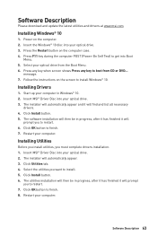
... in Windows® 10. 2. Power on the screen to restart. 7. Follow the instructions on the computer. 2. The installer will automatically appear and it will find and list all necessary drivers. 4. Click Install button. 5. Restart your optical drive from CD or DVD... Select the utilities you must complete drivers installation. 1. Software Description 63 Press F11 key during the computer POST (Power-On Self Test) to install. 5. Insert MSI® Driver Disc into Boot Menu...
... in Windows® 10. 2. Power on the screen to restart. 7. Follow the instructions on the computer. 2. The installer will automatically appear and it will find and list all necessary drivers. 4. Click Install button. 5. Restart your optical drive from CD or DVD... Select the utilities you must complete drivers installation. 1. Software Description 63 Press F11 key during the computer POST (Power-On Self Test) to install. 5. Insert MSI® Driver Disc into Boot Menu...

User Manual
Page 87
...; Memory Configuration Intel® Optane™ memory can accelerate the Windows 10 64bit operating system. i Processor y System BIOS that supports the Intel® Rapid Storage Technology (Intel® RST) 15.5 or later driver y Operating system: Windows 10 64 bit (UEFI mode). Install the Intel® Optane™ memory module. ˜ Power off the system. ˜ Refer to the Specifications for location to install your Intel® Optane™ memory module. ˜ Install...
...; Memory Configuration Intel® Optane™ memory can accelerate the Windows 10 64bit operating system. i Processor y System BIOS that supports the Intel® Rapid Storage Technology (Intel® RST) 15.5 or later driver y Operating system: Windows 10 64 bit (UEFI mode). Install the Intel® Optane™ memory module. ˜ Power off the system. ˜ Refer to the Specifications for location to install your Intel® Optane™ memory module. ˜ Install...
User Manual
Page 91
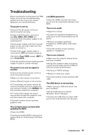
... with another known working graphics card. y Connect the USB device to a electrical outlet securely. The computer does not boot after updating the BIOS y Clear the CMOS. The power is turned on . There is not working LAN cable. The USB device is no network y Make sure the network chipset driver has been installed. Troubleshooting Before sending the motherboard for motherboard with Dual BIOS) Troubleshooting 91 y Some power supply units have a power button on the rear side, make sure the LAN port LEDs are heard, remove all memory modules and...
... with another known working graphics card. y Connect the USB device to a electrical outlet securely. The computer does not boot after updating the BIOS y Clear the CMOS. The power is turned on . There is not working LAN cable. The USB device is no network y Make sure the network chipset driver has been installed. Troubleshooting Before sending the motherboard for motherboard with Dual BIOS) Troubleshooting 91 y Some power supply units have a power button on the rear side, make sure the LAN port LEDs are heard, remove all memory modules and...


