User Manual
Page 13
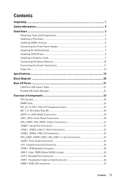
... Quick Start ...3 Preparing Tools and Components 3 Installing a Processor 4 Installing DDR4 memory 5 Connecting the Front Panel Header 6 Installing the Motherboard 7 Installing SATA Drives 8 Installing a Graphics Card 9 Connecting Peripheral Devices 10 Connecting the Power Connectors 11 Power On...12 Specifications...15 Block Diagram ...20 Rear I/O Panel ...21 LAN Port LED Status Table 21 Realtek HD Audio Manager 21 Overview of Components 23 CPU Socket ...25 DIMM Slots...26 PCI_E1~5, PCI1: PCIe/ PCI Expansion Slots 27 M2_1~2: M.2 Slots (Key M 28 SATA1~6: SATA 6Gb/s Connectors 29...
... Quick Start ...3 Preparing Tools and Components 3 Installing a Processor 4 Installing DDR4 memory 5 Connecting the Front Panel Header 6 Installing the Motherboard 7 Installing SATA Drives 8 Installing a Graphics Card 9 Connecting Peripheral Devices 10 Connecting the Power Connectors 11 Power On...12 Specifications...15 Block Diagram ...20 Rear I/O Panel ...21 LAN Port LED Status Table 21 Realtek HD Audio Manager 21 Overview of Components 23 CPU Socket ...25 DIMM Slots...26 PCI_E1~5, PCI1: PCIe/ PCI Expansion Slots 27 M2_1~2: M.2 Slots (Key M 28 SATA1~6: SATA 6Gb/s Connectors 29...
User Manual
Page 14
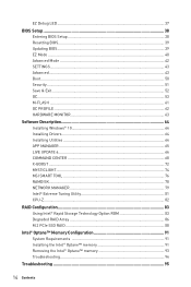
... Mode ...42 SETTINGS...43 Advanced...43 Boot...50 Security ...51 Save & Exit...52 OC...53 M-FLASH ...61 OC PROFILE ...62 HARDWARE MONITOR 63 Software Description 64 Installing Windows® 10 64 Installing Drivers 64 Installing Utilities 64 APP MANAGER ...65 LIVE UPDATE 6...66 COMMAND CENTER 68 X-BOOST ...72 MYSTICLIGHT...74 MSI SMART TOOL 76 RAMDISK...78 NETWORK MANAGER 79 Intel® Extreme Tuning Utility 81 CPU-Z...82 RAID Configuration 83 Using...
... Mode ...42 SETTINGS...43 Advanced...43 Boot...50 Security ...51 Save & Exit...52 OC...53 M-FLASH ...61 OC PROFILE ...62 HARDWARE MONITOR 63 Software Description 64 Installing Windows® 10 64 Installing Drivers 64 Installing Utilities 64 APP MANAGER ...65 LIVE UPDATE 6...66 COMMAND CENTER 68 X-BOOST ...72 MYSTICLIGHT...74 MSI SMART TOOL 76 RAMDISK...78 NETWORK MANAGER 79 Intel® Extreme Tuning Utility 81 CPU-Z...82 RAID Configuration 83 Using...

User Manual
Page 35
... configuration, set the jumper to default values 1. Plug the power cord and power on the motherboard to save system configuration data. Please refer to short JBAT1 for TPM (Trusted Platform Module). Overview of Components 35 JTPM1: TPM Module Connector This connector is external powered from JBAT1. 4. Remove the jumper cap from a battery located on the computer. Power off the computer and unplug the power cord 2. Keep Data (default) Clear CMOS/ Reset BIOS Resetting BIOS to clear the CMOS memory. Use a jumper...
... configuration, set the jumper to default values 1. Plug the power cord and power on the motherboard to save system configuration data. Please refer to short JBAT1 for TPM (Trusted Platform Module). Overview of Components 35 JTPM1: TPM Module Connector This connector is external powered from JBAT1. 4. Remove the jumper cap from a battery located on the computer. Power off the computer and unplug the power cord 2. Keep Data (default) Clear CMOS/ Reset BIOS Resetting BIOS to clear the CMOS memory. Use a jumper...
User Manual
Page 39
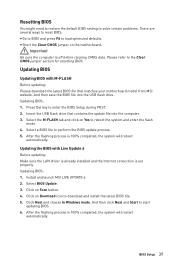
...flashing process is set properly. BIOS Setup 39 Select BIOS Update. 3. Insert the USB flash drive that matches your motherboard model from MSI website. Install and launch MSI LIVE UPDATE 6. 2. Click on the motherboard. Resetting BIOS You might need to restore the default BIOS setting to solve certain problems. There are several ways to reset BIOS: y Go to BIOS and press F6 to the Clear CMOS jumper section for resetting BIOS. y Short the Clear CMOS jumper on Download icon to enter the BIOS Setup during POST. 2. Select a BIOS file to start updating BIOS. 6. Updating BIOS...
...flashing process is set properly. BIOS Setup 39 Select BIOS Update. 3. Insert the USB flash drive that matches your motherboard model from MSI website. Install and launch MSI LIVE UPDATE 6. 2. Click on the motherboard. Resetting BIOS You might need to restore the default BIOS setting to solve certain problems. There are several ways to reset BIOS: y Go to BIOS and press F6 to the Clear CMOS jumper section for resetting BIOS. y Short the Clear CMOS jumper on Download icon to enter the BIOS Setup during POST. 2. Select a BIOS file to start updating BIOS. 6. Updating BIOS...
User Manual
Page 40
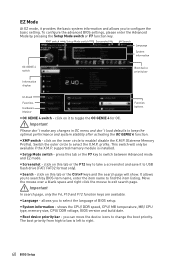
... circle to enable/ disable the X.M.P. (Extreme Memory Profile). profile. y Search - Important In search page, only the F6, F10 and F12 function keys are available. XMP switch Setup Mode switch Screenshot Search Language System information OC GENIE 4 switch Information display Boot device priority bar M-Flash Favorites Hardware Monitor Function buttons y OC GENIE 4 switch - Important Please don't make any changes in OC menu and don't load defaults to configure the basic setting. This switch will...
... circle to enable/ disable the X.M.P. (Extreme Memory Profile). profile. y Search - Important In search page, only the F6, F10 and F12 function keys are available. XMP switch Setup Mode switch Screenshot Search Language System information OC GENIE 4 switch Information display Boot device priority bar M-Flash Favorites Hardware Monitor Function buttons y OC GENIE 4 switch - Important Please don't make any changes in OC menu and don't load defaults to configure the basic setting. This switch will...
User Manual
Page 41
... one page. ƒ To add a BIOS item to a favorite page (Favorite 1~5) 1. y M-Flash - y Favorites - y Function buttons - enable or disable the LAN Option ROM, M.2/Optane Genie, Hardcore Mode, AHCI, RAID, CPU Fan Fail Warning Control and BIOS Log Review by percentage. click on this button to display the M-Flash menu that allows you to update BIOS with a USB flash drive. click on this button to display the Hardware Monitor menu that provides the way to select a BIOS menu (e.g. allows you to maximize system...
... one page. ƒ To add a BIOS item to a favorite page (Favorite 1~5) 1. y M-Flash - y Favorites - y Function buttons - enable or disable the LAN Option ROM, M.2/Optane Genie, Hardcore Mode, AHCI, RAID, CPU Fan Fail Warning Control and BIOS Log Review by percentage. click on this button to display the M-Flash menu that allows you to update BIOS with a USB flash drive. click on this button to display the Hardware Monitor menu that provides the way to select a BIOS menu (e.g. allows you to maximize system...

User Manual
Page 44
.... [Disabled] Disables the Ipv4 PXE boot support. 44 BIOS Setup f ACPI Settings Sets ACPI parameters of the onboard Power LED. [Dual Color] The power LED turns to another color to indicate the S3 state. [Blinking] The power LED blinks to indicate the S3 state. fOnboard LAN Controller [Enabled] Enables or disables the onboard LAN controller. This item will support Ipv4 protocol. fPEG X - f Integrated Peripherals Sets integrated peripherals' parameters, such as LAN, HDD, USB and audio. fNetwork Stack [Disabled] Sets UEFI network stack for detailed settings. Press Enter to utilize...
.... [Disabled] Disables the Ipv4 PXE boot support. 44 BIOS Setup f ACPI Settings Sets ACPI parameters of the onboard Power LED. [Dual Color] The power LED turns to another color to indicate the S3 state. [Blinking] The power LED blinks to indicate the S3 state. fOnboard LAN Controller [Enabled] Enables or disables the onboard LAN controller. This item will support Ipv4 protocol. fPEG X - f Integrated Peripherals Sets integrated peripherals' parameters, such as LAN, HDD, USB and audio. fNetwork Stack [Disabled] Sets UEFI network stack for detailed settings. Press Enter to utilize...

User Manual
Page 45
... mode for M.2 PCIe devices. fIntegrated Graphics Share Memory [64M] Selects a fixed amount of SATA storage device, such as the primary boot device. [IGD] Integrated Graphics Display. [PEG] PCI-Express Graphics Device. BIOS Setup 45 fHD Audio Controller [Enabled] Enables or disables the onboard High Definition Audio controller. fSATAx Hot Plug [Disabled] Allows user to enable or disable the SATA hot plug support. [Enabled] Enables hot plug support for the SATA ports. [Disabled] Disables hot plug support for both integrated and external graphics cards. [Disabled...
... mode for M.2 PCIe devices. fIntegrated Graphics Share Memory [64M] Selects a fixed amount of SATA storage device, such as the primary boot device. [IGD] Integrated Graphics Display. [PEG] PCI-Express Graphics Device. BIOS Setup 45 fHD Audio Controller [Enabled] Enables or disables the onboard High Definition Audio controller. fSATAx Hot Plug [Disabled] Allows user to enable or disable the SATA hot plug support. [Enabled] Enables hot plug support for the SATA ports. [Disabled] Disables hot plug support for both integrated and external graphics cards. [Disabled...
User Manual
Page 46
... and COM ports. fSerial (COM) Port x Configuration Sets detailed configuration of parallel port (LPT). Press to enter the submenu. fLegacy USB Support [Enabled] Sets Legacy USB function support. [Auto] The system will automatically detect if any USB device is connected and enable the legacy USB support. [Enabled] Enable the USB support under legacy mode. [Disabled] The USB devices will optimize the IRQ automatically or you can set it manually. 46 BIOS Setup If set to Auto, BIOS will be unavailable under legacy mode. Press to enter the submenu...
... and COM ports. fSerial (COM) Port x Configuration Sets detailed configuration of parallel port (LPT). Press to enter the submenu. fLegacy USB Support [Enabled] Sets Legacy USB function support. [Auto] The system will automatically detect if any USB device is connected and enable the legacy USB support. [Enabled] Enable the USB support under legacy mode. [Disabled] The USB devices will optimize the IRQ automatically or you can set it manually. 46 BIOS Setup If set to Auto, BIOS will be unavailable under legacy mode. Press to enter the submenu...

User Manual
Page 47
... S4 & S5 wake up by USB, PCI and PCIe devices. [Disabled] Disables this function. BIOS Setup 47 Press Enter to enter the submenu. fWindows 10 WHQL Support [Disabled] Enables the supports for Windows 10 or disables for parallel port. [STD Printer Mode] Printer port mode [SPP] Standard Parallel Port mode [EPP-1.9/ 1.7 + SPP] Enhanced Parallel Port-1.9/ 1.7 mode + Standard Parallel Port mode. [ECP] Extended Capability Port mode [ECP + EPP-1.9/ 1.7] Extended Capability Port mode + Enhanced Parallel Port-1.9/ 1.7 mode. f Power Management Setup Sets system Power Management of...
... S4 & S5 wake up by USB, PCI and PCIe devices. [Disabled] Disables this function. BIOS Setup 47 Press Enter to enter the submenu. fWindows 10 WHQL Support [Disabled] Enables the supports for Windows 10 or disables for parallel port. [STD Printer Mode] Printer port mode [SPP] Standard Parallel Port mode [EPP-1.9/ 1.7 + SPP] Enhanced Parallel Port-1.9/ 1.7 mode + Standard Parallel Port mode. [ECP] Extended Capability Port mode [ECP + EPP-1.9/ 1.7] Extended Capability Port mode + Enhanced Parallel Port-1.9/ 1.7 mode. f Power Management Setup Sets system Power Management of...
User Manual
Page 48
... Boot Mode sets to Custom. fSecure Boot Sets the Windows secure boot to select how the secure boot keys be available when MSI Fast Boot is enabled. This sub-menu will appear when Windows 10 WHQL Support is disabled. [Enabled] Enables the Fast Boot configuration to configure the secure boot settings and manually load the secure keys. This item is faster than the boot time of Fast Boot. [Enabled] Enables the MSI Fast Boot function to set the secure boot settings. [Disabled] Disables this function. Press to enter BIOS setup...
... Boot Mode sets to Custom. fSecure Boot Sets the Windows secure boot to select how the secure boot keys be available when MSI Fast Boot is enabled. This sub-menu will appear when Windows 10 WHQL Support is disabled. [Enabled] Enables the Fast Boot configuration to configure the secure boot settings and manually load the secure keys. This item is faster than the boot time of Fast Boot. [Enabled] Enables the MSI Fast Boot function to set the secure boot settings. [Disabled] Disables this function. Press to enter BIOS setup...
User Manual
Page 49
... state when activity of PS/2 mouse is detected. [Disabled] Disables this function. fResume By PCI-E Device [Disabled] Enables or disables the wake up function of installed PCI-E expansion cards, integrated LAN controllers or USB devices which are supported by third party integrated chips. [Enabled] Enables the system to select the date & time settings). fResume by USB Device [Disabled] Enables or disables the system wake up by PS/2 keyboard. [Any Key] Enables the system to be awakened from S3/ S4...
... state when activity of PS/2 mouse is detected. [Disabled] Disables this function. fResume By PCI-E Device [Disabled] Enables or disables the wake up function of installed PCI-E expansion cards, integrated LAN controllers or USB devices which are supported by third party integrated chips. [Enabled] Enables the system to select the date & time settings). fResume by USB Device [Disabled] Enables or disables the system wake up by PS/2 keyboard. [Any Key] Enables the system to be awakened from S3/ S4...

User Manual
Page 50
... mode and UEFI BIOS boot mode. f FIXED BOOT ORDER Priorities Sets device priority for 4 sec pon bootup. [Enabled] [Disabled] The system boots straight to Hot Key. Boot Sets the sequence of the ethernet controller parameter. f Boot Mode Select [LEGACY+UEFI] Sets the system boot mode from legacy or UEFI architecture depending on the screen. f Boot Option Priorities These items are used to be configured automatically by pressing the Power button for system boot. f Full Screen Logo Display [Enabled] Enables or disables to wake the system. f Intel ( R ) Ethernet Connection...
... mode and UEFI BIOS boot mode. f FIXED BOOT ORDER Priorities Sets device priority for 4 sec pon bootup. [Enabled] [Disabled] The system boots straight to Hot Key. Boot Sets the sequence of the ethernet controller parameter. f Boot Mode Select [LEGACY+UEFI] Sets the system boot mode from legacy or UEFI architecture depending on the screen. f Boot Option Priorities These items are used to be configured automatically by pressing the Power button for system boot. f Full Screen Logo Display [Enabled] Enables or disables to wake the system. f Intel ( R ) Ethernet Connection...
User Manual
Page 54
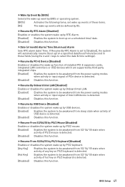
... BIOS Setup The valid value range depends on the installed CPU. This item appears when the installed CPU supports this function. [Enabled] Enables this function to the CPU loading. CPU ratio will be increased to adjust CPU voltage and core frequency dynamically. f Adjusted GT Frequency Shows the adjusted integrated graphics frequency. fEnhanced Turbo [Auto]* Enables or disables Enhanced Turbo function for all CPU cores to CPU features. f CPU Ratio Mode [Dynamic Mode]* Selects the CPU Ratio operating mode. Read-only. key...
... BIOS Setup The valid value range depends on the installed CPU. This item appears when the installed CPU supports this function. [Enabled] Enables this function to the CPU loading. CPU ratio will be increased to adjust CPU voltage and core frequency dynamically. f Adjusted GT Frequency Shows the adjusted integrated graphics frequency. fEnhanced Turbo [Auto]* Enables or disables Enhanced Turbo function for all CPU cores to CPU features. f CPU Ratio Mode [Dynamic Mode]* Selects the CPU Ratio operating mode. Read-only. key...
User Manual
Page 55
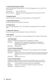
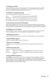
... the installed processor supports this value. f CPU Base Clock Apply Mode [Auto]* Sets the applying mode for overclocking the memory. is the overclocking technology by BIOS. [Next Boot] CPU will run the adjusted CPU base clock during boot. This item appears when a CPU that overclocking behavior and stability is not guaranteed. f Advanced DRAM Configuration Press Enter to load the default settings.) BIOS Setup 55 If it occurs, please clear the CMOS data and restore the default settings. (Refer to the Clear CMOS jumper/ button...
... the installed processor supports this value. f CPU Base Clock Apply Mode [Auto]* Sets the applying mode for overclocking the memory. is the overclocking technology by BIOS. [Next Boot] CPU will run the adjusted CPU base clock during boot. This item appears when a CPU that overclocking behavior and stability is not guaranteed. f Advanced DRAM Configuration Press Enter to load the default settings.) BIOS Setup 55 If it occurs, please clear the CMOS data and restore the default settings. (Refer to the Clear CMOS jumper/ button...

User Manual
Page 59
... memory for power-saving in halt state. fC1E Support [Disabled] Enables or disables the C1E function for Directed I/O) technology. This item appears when a CPU supports this function. This item appears when Intel C-State is enabled. [Enabled] Enables C1E function to automatically pre-fetch data and instructions into L2 cache from overheating. [Enabled] Throttles down the CPU core clock speed when the CPU is a processor power management technology defined by ACPI. [Auto] This setting will be configured...
... memory for power-saving in halt state. fC1E Support [Disabled] Enables or disables the C1E function for Directed I/O) technology. This item appears when a CPU supports this function. This item appears when Intel C-State is enabled. [Enabled] Enables C1E function to automatically pre-fetch data and instructions into L2 cache from overheating. [Enabled] Throttles down the CPU core clock speed when the CPU is a processor power management technology defined by ACPI. [Auto] This setting will be configured...
User Manual
Page 61
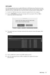
The system will enter the flash mode and a file selection menu will be prompted. Click on Yes to update BIOS. 1. Select a BIOS file to update BIOS with a USB flash drive. After the flashing process is 100% completed, the system will reboot automatically. Please down-load the latest BIOS file that contains the update file into your motherboard model from MSI website, save the BIOS file into the computer. 2. Insert the USB flash drive that matches your USB flash drive. M-FLASH M-FLASH provides the way...
The system will enter the flash mode and a file selection menu will be prompted. Click on Yes to update BIOS. 1. Select a BIOS file to update BIOS with a USB flash drive. After the flashing process is 100% completed, the system will reboot automatically. Please down-load the latest BIOS file that contains the update file into your motherboard model from MSI website, save the BIOS file into the computer. 2. Insert the USB flash drive that matches your USB flash drive. M-FLASH M-FLASH provides the way...

User Manual
Page 64
... progress, after it has finished it will find and list all necessary drivers. 4. Follow the instructions on the screen to finish. 8. Start up your optical drive. 3. Select the utilities you must complete drivers installation. 1. Click OK button to install Windows® 10. Insert the Windows® 10 disc into Boot Menu. 5. Press F11 key during the computer POST (Power-On Self Test) to get into your computer in...
... progress, after it has finished it will find and list all necessary drivers. 4. Follow the instructions on the screen to finish. 8. Start up your optical drive. 3. Select the utilities you must complete drivers installation. 1. Click OK button to install Windows® 10. Insert the Windows® 10 disc into Boot Menu. 5. Press F11 key during the computer POST (Power-On Self Test) to get into your computer in...
User Manual
Page 91
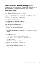
... M.2 slot. 3. Enable M.2/Optane Genie ˜ Power on this motherboard, just skip to install and remove the Intel® Optane™ memory. i Processor y System BIOS that supports the Intel® Rapid Storage Technology (Intel® RST) 15.5 or later driver y Operating system: Windows 10 64 bit (UEFI mode). Install the Intel® Rapid Storage Technology 15.5 ˜ Reboot to save configuration and exit. 4. System Requirements y Intel® Optane™ memory ready MSI® motherboards y Supported 7th...
... M.2 slot. 3. Enable M.2/Optane Genie ˜ Power on this motherboard, just skip to install and remove the Intel® Optane™ memory. i Processor y System BIOS that supports the Intel® Rapid Storage Technology (Intel® RST) 15.5 or later driver y Operating system: Windows 10 64 bit (UEFI mode). Install the Intel® Rapid Storage Technology 15.5 ˜ Reboot to save configuration and exit. 4. System Requirements y Intel® Optane™ memory ready MSI® motherboards y Supported 7th...
User Manual
Page 95
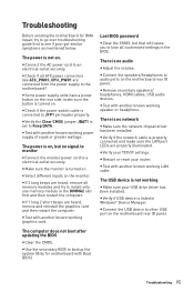
... troubleshooting guide first to see if your USB drive driver has been installed. y Some power supply units have a power button on the rear side, make sure the LAN port LEDs are heard, remove and reinstall the graphics card and then restart the computer. The power is not working graphics card. y Connect the USB device to Keep DATA. y Connect the AC power cord to JFP1 pin header properly. The USB device is on . y Remove secondary speakers/ headphones, HDMI cables, USB audio devices. y Use the secondary BIOS to install only one memory...
... troubleshooting guide first to see if your USB drive driver has been installed. y Some power supply units have a power button on the rear side, make sure the LAN port LEDs are heard, remove and reinstall the graphics card and then restart the computer. The power is not working graphics card. y Connect the USB device to Keep DATA. y Connect the AC power cord to JFP1 pin header properly. The USB device is on . y Remove secondary speakers/ headphones, HDMI cables, USB audio devices. y Use the secondary BIOS to install only one memory...


