User Manual
Page 11
... LED Status Table 20 Audio Ports Configuration 20 Realtek Audio Console 21 Overview of Components 23 CPU Socket ...25 DIMM Slots...26 PCI_E1~6: PCIe Expansion Slots 27 SATA1~6: SATA 6Gb/s Connectors 27 M2_1: M.2 Slot (Key M 28 JTPM1: TPM Module Connector 28 JFP1, JFP2: Front Panel Connectors 29 JCOM1: Serial Port Connector 29 JTBT1...
... LED Status Table 20 Audio Ports Configuration 20 Realtek Audio Console 21 Overview of Components 23 CPU Socket ...25 DIMM Slots...26 PCI_E1~6: PCIe Expansion Slots 27 SATA1~6: SATA 6Gb/s Connectors 27 M2_1: M.2 Slot (Key M 28 JTPM1: TPM Module Connector 28 JFP1, JFP2: Front Panel Connectors 29 JCOM1: Serial Port Connector 29 JTBT1...
User Manual
Page 13
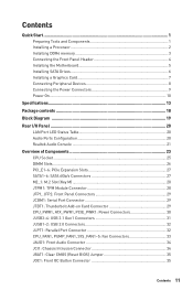
... Gen Intel® Core™ / Pentium® Gold / Celeron® processors for LGA 1151 socket * Please go to the latest version from MSI website. Intel® Z390 Chipset y 4x DDR4 memory slots, support up to 128GB* y Supports DDR4 4400(OC)/ 4300(OC)/ 4266(OC)/ 4200(OC)/ 4133(OC)/ 4000(OC)/ 3866(OC)/ 3733...
... Gen Intel® Core™ / Pentium® Gold / Celeron® processors for LGA 1151 socket * Please go to the latest version from MSI website. Intel® Z390 Chipset y 4x DDR4 memory slots, support up to 128GB* y Supports DDR4 4400(OC)/ 4300(OC)/ 4266(OC)/ 4200(OC)/ 4133(OC)/ 4000(OC)/ 3866(OC)/ 3733...

User Manual
Page 15
... y 1x 24-pin ATX main power connector y 1x 8-pin ATX 12V power connector y 1x 6-pin ATX 12V power connector y 6x SATA 6Gb/s connectors y 2x M.2 slots (1 M-Key slot,1 E-Key slot) y 2x USB 3.1 Gen1 connectors (supports additional 4 USB 3.1 Gen1 ports) y 2x USB 2.0 connectors (supports additional 4 USB 2.0 ports) y 1x 4-pin CPU fan connector y 1x 4-pin Water...
... y 1x 24-pin ATX main power connector y 1x 8-pin ATX 12V power connector y 1x 6-pin ATX 12V power connector y 6x SATA 6Gb/s connectors y 2x M.2 slots (1 M-Key slot,1 E-Key slot) y 2x USB 3.1 Gen1 connectors (supports additional 4 USB 3.1 Gen1 ports) y 2x USB 2.0 connectors (supports additional 4 USB 2.0 ports) y 1x 4-pin CPU fan connector y 1x 4-pin Water...
User Manual
Page 17
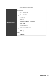
Special Features Continued from previous page y Protection ƒ PCI-E Steel Armor ƒ PCI-E Steel Slot y Performance ƒ Core Boost ƒ OC Genie ƒ Multi GPU-CrossFire Technology ƒ DDR4 Boost ƒ USB with type A+C ƒ Intel Turbo USB 3.1 Gen2 y VR ƒ VR Ready y BIOS ƒ Click BIOS 5 Specifications 17
Special Features Continued from previous page y Protection ƒ PCI-E Steel Armor ƒ PCI-E Steel Slot y Performance ƒ Core Boost ƒ OC Genie ƒ Multi GPU-CrossFire Technology ƒ DDR4 Boost ƒ USB with type A+C ƒ Intel Turbo USB 3.1 Gen2 y VR ƒ VR Ready y BIOS ƒ Click BIOS 5 Specifications 17
User Manual
Page 19
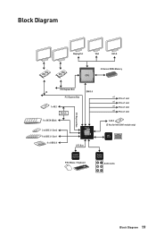
Block Diagram DisplayPort VGA DVI-D 2 Channel DDR4 Memory CPU PCI Express Bus x4 DMI 3.0 PCI Express Bus 1 x M.2 Switch 6 x SATA 6Gb/s 2 x USB 3.1 Gen2 6 x USB 3.1 Gen1 6 x USB 2.0 PCI Express Bus chipset LPC Bus x1 PCIe x1 slot x1 PCIe x1 slot x1 PCIe x1 slot x1 PCIe x1 slot 1x M.2 (E Key for Intel CNVi module only) Intel I219-V NV6797 Super I/O P/S2 Mouse / Keyboard Realtek ALC892 Audio Jacks Block Diagram 19
Block Diagram DisplayPort VGA DVI-D 2 Channel DDR4 Memory CPU PCI Express Bus x4 DMI 3.0 PCI Express Bus 1 x M.2 Switch 6 x SATA 6Gb/s 2 x USB 3.1 Gen2 6 x USB 3.1 Gen1 6 x USB 2.0 PCI Express Bus chipset LPC Bus x1 PCIe x1 slot x1 PCIe x1 slot x1 PCIe x1 slot x1 PCIe x1 slot 1x M.2 (E Key for Intel CNVi module only) Intel I219-V NV6797 Super I/O P/S2 Mouse / Keyboard Realtek ALC892 Audio Jacks Block Diagram 19

User Manual
Page 24
...CPU_FAN1, PUMP_FAN1, SYS_FAN1~5 Fan Connectors CPU_PWR1, ATX_PWR1, PCIE_PWR1 Power Connectors CPU Socket LGA 1151 Socket DIMMA1/A2/B1/B2 DIMM Slots JAUD1 Front Audio Connector JBAT1 Clear CMOS Jumper JCI1 Chassis Intrusion Connector JCOM1 Serial Port Connector JFP1, JFP2 Front Panel Connectors JLPT1 Parallel...LED connector Thunderbolt Add-on Card Connector TPM Module Connector JUSB1~2 USB 2.0 Connectors JUSB3~4 USB 3.1 Gen1 Connectors M2_1 M.2 Slot (Key M) PCI_E1~6 PCIe Expansion Slots SATA1~6 SATA 6Gb/s Connectors Page 33 30 25 26 34 35 34 29 29 32 35 36 29 28 32 31...
...CPU_FAN1, PUMP_FAN1, SYS_FAN1~5 Fan Connectors CPU_PWR1, ATX_PWR1, PCIE_PWR1 Power Connectors CPU Socket LGA 1151 Socket DIMMA1/A2/B1/B2 DIMM Slots JAUD1 Front Audio Connector JBAT1 Clear CMOS Jumper JCI1 Chassis Intrusion Connector JCOM1 Serial Port Connector JFP1, JFP2 Front Panel Connectors JLPT1 Parallel...LED connector Thunderbolt Add-on Card Connector TPM Module Connector JUSB1~2 USB 2.0 Connectors JUSB3~4 USB 3.1 Gen1 Connectors M2_1 M.2 Slot (Key M) PCI_E1~6 PCIe Expansion Slots SATA1~6 SATA 6Gb/s Connectors Page 33 30 25 26 34 35 34 29 29 32 35 36 29 28 32 31...
User Manual
Page 25
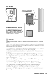
...is designed to protect the CPU from the power outlet before booting your system. MSI will deal with Return Merchandise Authorization (RMA) requests if only the motherboard comes... heatsink/ cooler, Please refer to the documentation in correctly lining up the CPU for more details about installation. MSI® does not guarantee the damages or risks caused by covering the socket with the protective cap on the ...CPU socket. CPU Socket Distance from the center of the CPU to the nearest DIMM slot. 50.77 mm Introduction to the LGA 1151 CPU The surface of the LGA 1151 CPU has two...
...is designed to protect the CPU from the power outlet before booting your system. MSI will deal with Return Merchandise Authorization (RMA) requests if only the motherboard comes... heatsink/ cooler, Please refer to the documentation in correctly lining up the CPU for more details about installation. MSI® does not guarantee the damages or risks caused by covering the socket with the protective cap on the ...CPU socket. CPU Socket Distance from the center of the CPU to the nearest DIMM slot. 50.77 mm Introduction to the LGA 1151 CPU The surface of the LGA 1151 CPU has two...

User Manual
Page 26
... CPU. y The stability and compatibility of installed memory module depend on the motherboard. y It is suggested to BIOS and find the Memory Try It! DIMM Slots DIMMA1 DIMMB1 Channel A Channel B DIMMA2 Memory module installation recommendation DIMMB2 DIMMA2 DIMMB2 DIMMA2 DIMMB2 DIMMB1 DIMMA2 DIMMA1 Important y Always insert memory modules in the DIMMA2...
... CPU. y The stability and compatibility of installed memory module depend on the motherboard. y It is suggested to BIOS and find the Memory Try It! DIMM Slots DIMMA1 DIMMB1 Channel A Channel B DIMMA2 Memory module installation recommendation DIMMB2 DIMMA2 DIMMB2 DIMMA2 DIMMB2 DIMMB1 DIMMA2 DIMMA1 Important y Always insert memory modules in the DIMMA2...
User Manual
Page 27
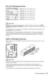
...Expansion Slots PCI_E1: PCIe 3.0 x16 (CPU lanes) PCI_E2: PCIe 3.0 x1 (PCH lanes) PCI_E3: PCIe 3.0 x1 (PCH lanes) PCI_E4: PCIe 3.0 x4 (PCH lanes) PCI_E5: PCIe 3.0 x1 (PCH lanes) PCI_E6: PCIe 3.0 x1 (PCH lanes) Important y If you install a large and heavy graphics card, you need to use a tool such as MSI Gaming... SATA5 Important y Please do not fold the SATA cable at a 90-degree angle. y SATA cables have identical plugs on either sides of the slot. y The SATA2 will be connected to one SATA device. y When adding or removing expansion cards, always turn off the power supply and unplug ...
...Expansion Slots PCI_E1: PCIe 3.0 x16 (CPU lanes) PCI_E2: PCIe 3.0 x1 (PCH lanes) PCI_E3: PCIe 3.0 x1 (PCH lanes) PCI_E4: PCIe 3.0 x4 (PCH lanes) PCI_E5: PCIe 3.0 x1 (PCH lanes) PCI_E6: PCIe 3.0 x1 (PCH lanes) Important y If you install a large and heavy graphics card, you need to use a tool such as MSI Gaming... SATA5 Important y Please do not fold the SATA cable at a 90-degree angle. y SATA cables have identical plugs on either sides of the slot. y The SATA2 will be connected to one SATA device. y When adding or removing expansion cards, always turn off the power supply and unplug ...
User Manual
Page 28
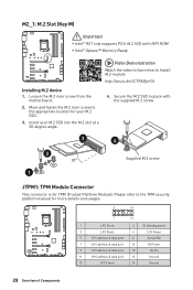
... ROM. Loosen the M.2 riser screw from the motherboard. 2. Move and fasten the M.2 riser screw to the appropriate location for your M.2 SSD into the M.2 slot at a 30-degree angle. 4. M2_1: M.2 Slot (Key M) Important y Intel® RST only supports PCIe M.2 SSD with the supplied M.2 screw. 3 4 2 30° Supplied M.2 screw 1 JTPM1: TPM Module Connector This...
... ROM. Loosen the M.2 riser screw from the motherboard. 2. Move and fasten the M.2 riser screw to the appropriate location for your M.2 SSD into the M.2 slot at a 30-degree angle. 4. M2_1: M.2 Slot (Key M) Important y Intel® RST only supports PCIe M.2 SSD with the supplied M.2 screw. 3 4 2 30° Supplied M.2 screw 1 JTPM1: TPM Module Connector This...
User Manual
Page 32
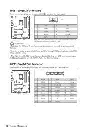
... connecting to recharge your iPad,iPhone and iPod through USB ports, please install MSI Dragon Center utility. y The CNVI_1 and JUSB2 share the same bandwidth. y In order to JUSB2 is installed in the CNVI_1 slot. y Note that the VCC and Ground pins must be connected correctly to ... PE 24 Ground 25 SLCT 26 No Pin 32 Overview of pins is unavailable when a Intel wireless-AC (CNVi) module is unavailable when the CNVI_1 slot has been installed. JLPT1: Parallel Port Connector This connector allows you to connect USB 2.0 ports on the front panel. 2 10 Note 1 9 1 VCC 2 ...
... connecting to recharge your iPad,iPhone and iPod through USB ports, please install MSI Dragon Center utility. y The CNVI_1 and JUSB2 share the same bandwidth. y In order to JUSB2 is installed in the CNVI_1 slot. y Note that the VCC and Ground pins must be connected correctly to ... PE 24 Ground 25 SLCT 26 No Pin 32 Overview of pins is unavailable when a Intel wireless-AC (CNVi) module is unavailable when the CNVI_1 slot has been installed. JLPT1: Parallel Port Connector This connector allows you to connect USB 2.0 ports on the front panel. 2 10 Note 1 9 1 VCC 2 ...
User Manual
Page 38
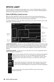
... area you wish, and then select a LED effect from the list and you choose will be a list of auto-detected devices on the top of MSI & partner products. In this section, you want. Then use the page navigation on the bottom to find more or less depending on the outer or... light effects (Stack, Breathing, Flashing etc.). Drag the brightness slider up MYSTIC LIGHT, there will only list the light effects which are four custom color slots on the outer arc and six unchangeable default colors on the outer arc to store the color of effect selector lists six effects, you start...
... area you wish, and then select a LED effect from the list and you choose will be a list of auto-detected devices on the top of MSI & partner products. In this section, you want. Then use the page navigation on the bottom to find more or less depending on the outer or... light effects (Stack, Breathing, Flashing etc.). Drag the brightness slider up MYSTIC LIGHT, there will only list the light effects which are four custom color slots on the outer arc and six unchangeable default colors on the outer arc to store the color of effect selector lists six effects, you start...
User Manual
Page 47
... enter the submenu. fOnboard LAN Controller [Enabled] Enables or disables the onboard LAN controller. fPEG X - fPCI Latency Timer [32] Sets latency timer of PCIe x16 slots for matching different installed devices. [Auto] This item will appear when Onboard LAN Controller is enabled. [Enabled] Enables the onboard LAN Boot ROM. [Disabled] Disables...
... enter the submenu. fOnboard LAN Controller [Enabled] Enables or disables the onboard LAN controller. fPEG X - fPCI Latency Timer [32] Sets latency timer of PCIe x16 slots for matching different installed devices. [Auto] This item will appear when Onboard LAN Controller is enabled. [Enabled] Enables the onboard LAN Boot ROM. [Disabled] Disables...
User Manual
Page 71
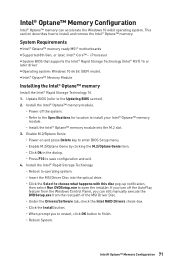
...Intel® Optane™ Memory Configuration Intel® Optane™ memory can still manually execute the DVDSetup.exe from the root path of the MSI Driver Disc. ˜ Under the Drivers/Software tab, check the Intel RAID Drivers check-box. ˜ Click the Install button. ˜... and remove the Intel® Optane™ memory. Update BIOS (refer to open the installer. System Requirements y Intel® Optane™ memory ready MSI® motherboards y Supported 8th Gen, or later, Intel® Core™ - Install the Intel® Rapid Storage Technology ˜ Reboot to operating...
...Intel® Optane™ Memory Configuration Intel® Optane™ memory can still manually execute the DVDSetup.exe from the root path of the MSI Driver Disc. ˜ Under the Drivers/Software tab, check the Intel RAID Drivers check-box. ˜ Click the Install button. ˜... and remove the Intel® Optane™ memory. Update BIOS (refer to open the installer. System Requirements y Intel® Optane™ memory ready MSI® motherboards y Supported 8th Gen, or later, Intel® Core™ - Install the Intel® Rapid Storage Technology ˜ Reboot to operating...
User Manual
Page 74
... on the rear side, make sure the LAN port LEDs are connected from the power supply to install only one memory module in the DIMMA2 slot first and then restart the computer. y Test with another known working y Make sure your got similar symptoms as mentioned below. Lost BIOS password y Clear the...
... on the rear side, make sure the LAN port LEDs are connected from the power supply to install only one memory module in the DIMMA2 slot first and then restart the computer. y Test with another known working y Make sure your got similar symptoms as mentioned below. Lost BIOS password y Clear the...


