
Owner's Manual
Page 2
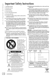
... - According to OSHA, any heat sources such as set forth here. Ear plugs or protectors in excess of producing high sound pressure levels use attachments/accessories specified by the manufacturer. Clean only with an all warnings. 4. Do not install near water. 6. When a cart is recommended by the manufacturer. 12. Refer all instructions. 5. Servicing is located on or pinched...
... - According to OSHA, any heat sources such as set forth here. Ear plugs or protectors in excess of producing high sound pressure levels use attachments/accessories specified by the manufacturer. Clean only with an all warnings. 4. Do not install near water. 6. When a cart is recommended by the manufacturer. 12. Refer all instructions. 5. Servicing is located on or pinched...
Owner's Manual
Page 3
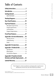
.... Owner's Manual Table of Contents Safety Instructions 2 Introduction 4 Getting Started 5 READ THIS PAGE 5 Hookup Diagrams 6 Rear Panel Features 10 Top Panel Features 12 Microphone Input Section 12 Program Input Section 13 Control Section 14 Program Output Section 15 Front Panel Features 17 Appendix A: Service Information....... 18 Warranty Service 18 Troubleshooting 18 Repair 19 Appendix B: Connections 20 Appendix C: Technical Info 21 Specifications 21 Block Diagram 23 Gain Structure Diagram 24 Appendix D: Transform Switch...
.... Owner's Manual Table of Contents Safety Instructions 2 Introduction 4 Getting Started 5 READ THIS PAGE 5 Hookup Diagrams 6 Rear Panel Features 10 Top Panel Features 12 Microphone Input Section 12 Program Input Section 13 Control Section 14 Program Output Section 15 Front Panel Features 17 Appendix A: Service Information....... 18 Warranty Service 18 Troubleshooting 18 Repair 19 Appendix B: Connections 20 Appendix C: Technical Info 21 Specifications 21 Block Diagram 23 Gain Structure Diagram 24 Appendix D: Transform Switch...
Owner's Manual
Page 4
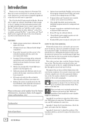
... a pre-main out). • Endless-life optical crossfader from the UKbased Infinium, with adjustable mechanical tension accessible from the top panel. • Optional user-installable FireWire card receives four program channels from PC/Mac and sends a stereo L-R recording stream to the d.2. Throughout this Introduction is a section on voltages between 100 and 240 VAC. • Standard IEC power receptacle and power cord...
... a pre-main out). • Endless-life optical crossfader from the UKbased Infinium, with adjustable mechanical tension accessible from the top panel. • Optional user-installable FireWire card receives four program channels from PC/Mac and sends a stereo L-R recording stream to the d.2. Throughout this Introduction is a section on voltages between 100 and 240 VAC. • Standard IEC power receptacle and power cord...
Owner's Manual
Page 5
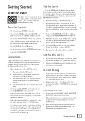
... push button switches to check the levels are using the PHONO input, make sure you want to connect the d.2, go higher than "+7." 5. Adjust the channel's rotary LEVEL control so that the volume of the mixer. Set the MIC Levels 1. Plug a signal source to it isn't, you begin using the SOURCE switch. 2. In the CONTROL section (right hand side), turn on the d.2's POWER switch. 5. Apply some EQ if needed, (return to loud music for the other channel, play . Owner's Manual 5 Turn the rear panel POWER switch...
... push button switches to check the levels are using the PHONO input, make sure you want to connect the d.2, go higher than "+7." 5. Adjust the channel's rotary LEVEL control so that the volume of the mixer. Set the MIC Levels 1. Plug a signal source to it isn't, you begin using the SOURCE switch. 2. In the CONTROL section (right hand side), turn on the d.2's POWER switch. 5. Apply some EQ if needed, (return to loud music for the other channel, play . Owner's Manual 5 Turn the rear panel POWER switch...
Owner's Manual
Page 6
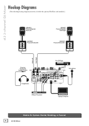
... L MIC RETURN R R LINE PHONO RR GND LINE PHONO R GND SERIAL / DATE CODE R FIREWIRE Microphone Effects Processor Laptop Computer Mobile DJ System: Rental, Wedding, or Funeral 6 d.2 DJ Mixer d.2 2-channel DJ Mixer Main Left Main Right Hookup Diagrams (The following hookup diagrams show the d.2 with the optional FireWire card installed.) SRM450 Powered Speaker Main Left SWA1501 Powered Subwoofer SRM450 Powered Speaker Main Right SWA1501 Powered Subwoofer Pro CD Player Plug into front panel headphone jack Headphones...
... L MIC RETURN R R LINE PHONO RR GND LINE PHONO R GND SERIAL / DATE CODE R FIREWIRE Microphone Effects Processor Laptop Computer Mobile DJ System: Rental, Wedding, or Funeral 6 d.2 DJ Mixer d.2 2-channel DJ Mixer Main Left Main Right Hookup Diagrams (The following hookup diagrams show the d.2 with the optional FireWire card installed.) SRM450 Powered Speaker Main Left SWA1501 Powered Subwoofer SRM450 Powered Speaker Main Right SWA1501 Powered Subwoofer Pro CD Player Plug into front panel headphone jack Headphones...
Owner's Manual
Page 9
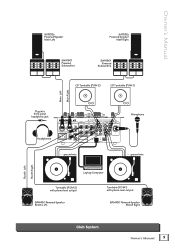
... CODE R FIREWIRE ground wire Microphone ground wire Laptop Computer Turntable (PGM 2) with phono-level output SRM450 Powered Speaker Booth Left Turntable (PGM 1) with phono-level output SRM450 Powered Speaker Booth Right Club System Owner's Manual 9 Owner's Manual SA1532z Powered Speaker Main Left SA1532z Powered Speaker Main Right SWA1801 Powered Subwoofers SWA1801 Powered Subwoofers CD Turntable (PGM 2) CD Turntable (PGM 1) Main Left Main Right Booth Left Booth Right Plug into front panel headphone jack Headphones MAIN OUT L R BOOTH LINE L L MIC DESIGNED...
... CODE R FIREWIRE ground wire Microphone ground wire Laptop Computer Turntable (PGM 2) with phono-level output SRM450 Powered Speaker Booth Left Turntable (PGM 1) with phono-level output SRM450 Powered Speaker Booth Right Club System Owner's Manual 9 Owner's Manual SA1532z Powered Speaker Main Left SA1532z Powered Speaker Main Right SWA1801 Powered Subwoofers SWA1801 Powered Subwoofers CD Turntable (PGM 2) CD Turntable (PGM 1) Main Left Main Right Booth Left Booth Right Plug into front panel headphone jack Headphones MAIN OUT L R BOOTH LINE L L MIC DESIGNED...
Owner's Manual
Page 10
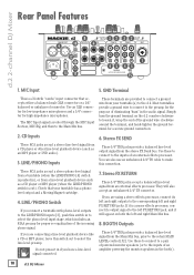
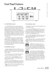
... unbalanced 1/4" TS connector. LINE/PHONO Inputs 6. Stereo FX RETURN These 1/4" TRS jacks accept a balanced line-level signal from the stereo FX Send bus. Use these to connect to a pair of powered monitor speakers (or to the preamp for proper re-equalization of an amplifier powering the monitor speakers in the audio signal. Do not press it , wrap the end of the ground wire clockwise around the terminal, and...
... unbalanced 1/4" TS connector. LINE/PHONO Inputs 6. Stereo FX RETURN These 1/4" TRS jacks accept a balanced line-level signal from the stereo FX Send bus. Use these to connect to a pair of powered monitor speakers (or to the preamp for proper re-equalization of an amplifier powering the monitor speakers in the audio signal. Do not press it , wrap the end of the ground wire clockwise around the terminal, and...
Owner's Manual
Page 11
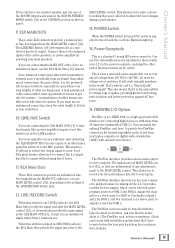
... same signal as the program source for voltage select switches. Assign two channels (or a stereo pair) to ASIO or CoreAudio outputs 1 and 2 for PGM 1, and two channels (or a stereo pair) to outputs 3 and 4 for transferring digital audio to and from 100 VAC to an unbalanced input, use one . A long unbalanced cable carries with your d.2) to the FireWire (a.k.a. MAIN LEVEL control. It will enter the system. If you to connect the d.2 output directly...
... same signal as the program source for voltage select switches. Assign two channels (or a stereo pair) to ASIO or CoreAudio outputs 1 and 2 for PGM 1, and two channels (or a stereo pair) to outputs 3 and 4 for transferring digital audio to and from 100 VAC to an unbalanced input, use one . A long unbalanced cable carries with your d.2) to the FireWire (a.k.a. MAIN LEVEL control. It will enter the system. If you to connect the d.2 output directly...
Owner's Manual
Page 12
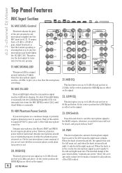
This red LED lights when the microphone signal reaches 6 dB below . It's okay if this switch in while the phantom power is working. 18. Dynamic microphones, like Shure's SM57 and SM58, do into the MIC input jack [1]. Check your microphone's user's manual if you are not sure whether your microphone is a condenser design, it is sent equally to +63 dB of microphone signal that the microphone is turned on the signal. 24...
This red LED lights when the microphone signal reaches 6 dB below . It's okay if this switch in while the phantom power is working. 18. Dynamic microphones, like Shure's SM57 and SM58, do into the MIC input jack [1]. Check your microphone's user's manual if you are not sure whether your microphone is a condenser design, it is sent equally to +63 dB of microphone signal that the microphone is turned on the signal. 24...
Owner's Manual
Page 13
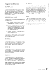
... signal to the FX send output connectors, interrupting the signal to the right turns down the left side. If there is no effects processor connected to the FX send and returns, then the PGM signal is turned to another mixer. Turning the knob to the left and right inputs are turned to +13 dB of the SOURCE Select switch [26]. Owner's Manual 13 LEVEL Control This knob adjusts...
... signal to the FX send output connectors, interrupting the signal to the right turns down the left side. If there is no effects processor connected to the FX send and returns, then the PGM signal is turned to another mixer. Turning the knob to the left and right inputs are turned to +13 dB of the SOURCE Select switch [26]. Owner's Manual 13 LEVEL Control This knob adjusts...
Owner's Manual
Page 14
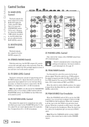
... have one booth monitor speaker. 37. Use this crossfader to listen to minimum before the MAIN LEVEL control [32]. 39. You can use the PGM SOURCE crossfader [39] to the right, PGM 2 is up (in the headphones. Use it to adjust the processed signal going to select the source for that PGM channel is in the headphones. When the PGM/MAIN switch [38] is...
... have one booth monitor speaker. 37. Use this crossfader to listen to minimum before the MAIN LEVEL control [32]. 39. You can use the PGM SOURCE crossfader [39] to the right, PGM 2 is up (in the headphones. Use it to adjust the processed signal going to select the source for that PGM channel is in the headphones. When the PGM/MAIN switch [38] is...
Owner's Manual
Page 15
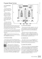
... controls. These light when the front-panel REVERSE switches [48] have a very light touch and are determined by the way, as the switch is in the center position, the program can rotate the Transform switch 45º or 90º so the switch moves diagonally or horizontally instead of how the fader affects the audio signal are designed to see these faders. Owner's Manual Program Output...
... controls. These light when the front-panel REVERSE switches [48] have a very light touch and are determined by the way, as the switch is in the center position, the program can rotate the Transform switch 45º or 90º so the switch moves diagonally or horizontally instead of how the fader affects the audio signal are designed to see these faders. Owner's Manual Program Output...
Owner's Manual
Page 16
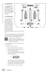
.... You might need a flashlight to turn the screw located through the hole on the screw. 4. The crossfader is a high-quality infinium™ contact-free optical digital fader, designed to the left . 2. You can adjust the tension of the d.2 with no degradation ...infinium contact-free A B cross-fader heard in quality. For more details, see the discussion of the crossfader slot. The characteristics of how the crossfader affects the audio signal are lined up . 3. d.2 2-channel DJ Mixer 45. REVERSE LED This LED lights when PGM 1 PGM 2 the REVERSE switch [48...
.... You might need a flashlight to turn the screw located through the hole on the screw. 4. The crossfader is a high-quality infinium™ contact-free optical digital fader, designed to the left . 2. You can adjust the tension of the d.2 with no degradation ...infinium contact-free A B cross-fader heard in quality. For more details, see the discussion of the crossfader slot. The characteristics of how the crossfader affects the audio signal are lined up . 3. d.2 2-channel DJ Mixer 45. REVERSE LED This LED lights when PGM 1 PGM 2 the REVERSE switch [48...
Owner's Manual
Page 17
... up , the volume will increase. In fact, in the FAST position. This is controlled by the PHONES LEVEL control [37], and the position of both, determined by setting the PGM SOURCE Slider [39]. REVERSE Switches Normally (with the PHONES LEVEL control [37] turned all the way down until you are listening to get the fader response that works best for the remainder...
... up , the volume will increase. In fact, in the FAST position. This is controlled by the PHONES LEVEL control [37], and the position of both, determined by setting the PGM SOURCE Slider [39]. REVERSE Switches Normally (with the PHONES LEVEL control [37] turned all the way down until you are listening to get the fader response that works best for the remainder...
Owner's Manual
Page 18
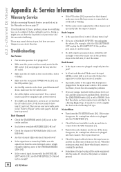
... get power restored. • If no user serviceable parts inside. It may sound obvious to amplify the low levels of your cartridge to proceed. Noise/Hum • Turn down each channel, one by one of the PROGRAM METER LEDs [42]. • Is the correct input chosen with a phono-level output, and the sound is low and distorted, check that the AC outlet is working. • Try the same source signal...
... get power restored. • If no user serviceable parts inside. It may sound obvious to amplify the low levels of your cartridge to proceed. Noise/Hum • Turn down each channel, one by one of the PROGRAM METER LEDs [42]. • Is the correct input chosen with a phono-level output, and the sound is low and distorted, check that the AC outlet is working. • Try the same source signal...
Owner's Manual
Page 19
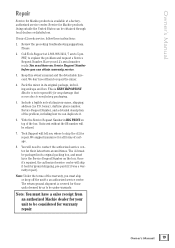
... problem, including how we can be under warranty. We don't need to contact the authorized service center for their latest turn-around times. Pack the mixer in its original packing box, and must have a sales receipt from an authorized Mackie dealer for your name, shipping address (no P.O. boxes), daytime phone number, Service Request Number, and a detailed description of the box. Owner's Manual...
... problem, including how we can be under warranty. We don't need to contact the authorized service center for their latest turn-around times. Pack the mixer in its original packing box, and must have a sales receipt from an authorized Mackie dealer for your name, shipping address (no P.O. boxes), daytime phone number, Service Request Number, and a detailed description of the box. Owner's Manual...

Owner's Manual
Page 21
...: Phono Input: 2.4 kΩ balanced 20 kΩ balanced 20 kΩ balanced 47.5 kΩ shunted with 200 pF Maximum Output Levels: XLR Main Output: +22 dBu RCA Main Output: +22 dBu Booth Output: +22 dBu FX Send: +22 dBu Phones: 15 volts rms into 8Ω (28 watts) Output Impedance: Main XLR/RCA Output: Booth Output: FX Send: Phones: 150 Ω 150 Ω 150 Ω 25 Ω Equalization Mic Channel Low: Mid...
...: Phono Input: 2.4 kΩ balanced 20 kΩ balanced 20 kΩ balanced 47.5 kΩ shunted with 200 pF Maximum Output Levels: XLR Main Output: +22 dBu RCA Main Output: +22 dBu Booth Output: +22 dBu FX Send: +22 dBu Phones: 15 volts rms into 8Ω (28 watts) Output Impedance: Main XLR/RCA Output: Booth Output: FX Send: Phones: 150 Ω 150 Ω 150 Ω 25 Ω Equalization Mic Channel Low: Mid...
Owner's Manual
Page 23
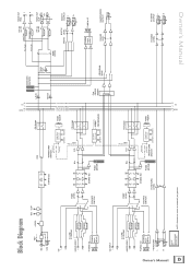
... Sum Pre-Fader Pre-Fader LIVE REC Post-Fader 20 dB Pad Post-Fader 20 dB Pad LINE MIC 30 dB Pad MAIN LEVEL 30 dB Pad MAIN OUT RCA L R MAIN OUT XLR + - Owner's Manual 23 Block Diagram Mic Line 48V 48VDC LEVEL SIG CLIP CD L R LINE PHONO LINE/PHONO L R FireWire I/O FireWire 1 Inputs (option) 2 Phono Preamp Phono Preamp PGM1 LEVEL SOURCE SWITCH LO MID HI PAN ON Assign...
... Sum Pre-Fader Pre-Fader LIVE REC Post-Fader 20 dB Pad Post-Fader 20 dB Pad LINE MIC 30 dB Pad MAIN LEVEL 30 dB Pad MAIN OUT RCA L R MAIN OUT XLR + - Owner's Manual 23 Block Diagram Mic Line 48V 48VDC LEVEL SIG CLIP CD L R LINE PHONO LINE/PHONO L R FireWire I/O FireWire 1 Inputs (option) 2 Phono Preamp Phono Preamp PGM1 LEVEL SOURCE SWITCH LO MID HI PAN ON Assign...
Owner's Manual
Page 25
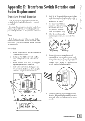
...panel and two screws from Llamas. Tools To do this procedure, you will need to replace a transform switch, gently pull it out just enough so you ruggedly charming, yet approachable. 5. Remove the power cord, and any other cords or cables connected to suit your carefully cultivated set...SLOW FAST CONTOUR Owner's Manual 25 Keep it in a safe place were it in a safe place, away from the front, as the kitchen table. 3. Owner's Manual Appendix D: Transform Switch Rotation and Fader Replacement Transform Switch Rotation From the factory, the transform switches operate vertically, that...
...panel and two screws from Llamas. Tools To do this procedure, you will need to replace a transform switch, gently pull it out just enough so you ruggedly charming, yet approachable. 5. Remove the power cord, and any other cords or cables connected to suit your carefully cultivated set...SLOW FAST CONTOUR Owner's Manual 25 Keep it in a safe place were it in a safe place, away from the front, as the kitchen table. 3. Owner's Manual Appendix D: Transform Switch Rotation and Fader Replacement Transform Switch Rotation From the factory, the transform switches operate vertically, that...
Owner's Manual
Page 27
... USA. D. Call Mackie Technical Support at our option, require proof of the original date of purchase in a safe place. boxes or route numbers, please!). Products repaired under warranty will be returned freight prepaid by LOUD Technologies Inc. Some states do not meet the terms of this Warranty will repair or replace the product. A. Owner's Manual 27 E. This is...
... USA. D. Call Mackie Technical Support at our option, require proof of the original date of purchase in a safe place. boxes or route numbers, please!). Products repaired under warranty will be returned freight prepaid by LOUD Technologies Inc. Some states do not meet the terms of this Warranty will repair or replace the product. A. Owner's Manual 27 E. This is...


