

Owners Manual
Page 12
... Remote CPU. 3. These outputs are wired balanced when using a tip-ring-sleeve connector or unbalanced when using a 17-inch or larger monitor for best results. The sound you must use a UPS (Uninterruptible Power Supply) and a surge protector on the back of the Remote CPU. Powered Monitors Connect directly from amp to the line inputs on the powered monitors. Line Cable MASTER OUT LR CR MAIN LR CR NEAR FIELD LR Line Cable Speaker Cable Speaker Cable Note: The Remote...
... Remote CPU. 3. These outputs are wired balanced when using a tip-ring-sleeve connector or unbalanced when using a 17-inch or larger monitor for best results. The sound you must use a UPS (Uninterruptible Power Supply) and a surge protector on the back of the Remote CPU. Powered Monitors Connect directly from amp to the line inputs on the powered monitors. Line Cable MASTER OUT LR CR MAIN LR CR NEAR FIELD LR Line Cable Speaker Cable Speaker Cable Note: The Remote...

Owners Manual
Page 14
... the MIC button down for a microphone or is in the up position for digital connections, it 's in Fader Bank 3 providing another 8 inputs. Be sure the microphone or instrument is plugged into Channel 1 and that the ASSIGN button on Channel One lights up green. • In the CONTROL ROOM section, select MASTER L-R. • Select the desired SPEAKERS in a compact package. You'll find that will become second nature as you hear sound...
... the MIC button down for a microphone or is in the up position for digital connections, it 's in Fader Bank 3 providing another 8 inputs. Be sure the microphone or instrument is plugged into Channel 1 and that the ASSIGN button on Channel One lights up green. • In the CONTROL ROOM section, select MASTER L-R. • Select the desired SPEAKERS in a compact package. You'll find that will become second nature as you hear sound...

Owners Manual
Page 15
... the Microphone Signal Path Follow this button sends whatever is coming from the MASTER L/R fader to Hear 5. Assigning this graphic map to quickly complete a signal path using a microphone to -10 on the channel one meter. CONTROL ROOM 2 TRACK A DIGITAL IN 1 2 TRACK B DIGITAL IN 2 2 TRACK C MASTER L-R MONO OR NEAR FIELD MAIN SPEAKERS SPEAKER LEVEL DIM TALKBACK D8B Manual • Chapter 1 • page 9 FAST TRACK Power On Speakers On and Connected to Mixer Mic...
... the Microphone Signal Path Follow this button sends whatever is coming from the MASTER L/R fader to Hear 5. Assigning this graphic map to quickly complete a signal path using a microphone to -10 on the channel one meter. CONTROL ROOM 2 TRACK A DIGITAL IN 1 2 TRACK B DIGITAL IN 2 2 TRACK C MASTER L-R MONO OR NEAR FIELD MAIN SPEAKERS SPEAKER LEVEL DIM TALKBACK D8B Manual • Chapter 1 • page 9 FAST TRACK Power On Speakers On and Connected to Mixer Mic...

Owners Manual
Page 25
... the "Erase UFX Memory" and "Upgrade UFX Cards" procedures (under Windows in update. Depending on the D8B control surface. (Note: The installer no longer uses the VGA screen; Once the disk has been ejected from the Utilities menu. 5. Follow the instructions on your version of Disk Copy, you know which is about 30 seconds.) D8B Manual • Chapter 1 • page 19...
... the "Erase UFX Memory" and "Upgrade UFX Cards" procedures (under Windows in update. Depending on the D8B control surface. (Note: The installer no longer uses the VGA screen; Once the disk has been ejected from the Utilities menu. 5. Follow the instructions on your version of Disk Copy, you know which is about 30 seconds.) D8B Manual • Chapter 1 • page 19...

Owners Manual
Page 41
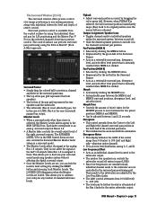
... key and adjusting the Speaker Level V-Pot. Selection choices include -20 dB, -30 dB, -40 dB, and -inf dB (Cut). CLIPBOARD CUT/ZERO SET PASTE COPY UNDO CUT/ZERO SET button • Deletes edited parameters from the currently selected channel(s) and returns them to set a fixed level offset between monitor sets. • Controls the Master Surround Monitor output when in mono. DIGITAL IN 2 button Selects the S/PDIF digital input as the Control Room source (when S/PDIF...
... key and adjusting the Speaker Level V-Pot. Selection choices include -20 dB, -30 dB, -40 dB, and -inf dB (Cut). CLIPBOARD CUT/ZERO SET PASTE COPY UNDO CUT/ZERO SET button • Deletes edited parameters from the currently selected channel(s) and returns them to set a fixed level offset between monitor sets. • Controls the Master Surround Monitor output when in mono. DIGITAL IN 2 button Selects the S/PDIF digital input as the Control Room source (when S/PDIF...
Owners Manual
Page 79
.... Low Frequency Effect • Acts as a retrievable surround pan, divergence level, and sub-effect level preset that is instantly recalled when MEM A is the rear (surround) panned bus output. Surround position control is selected, the Monitor Levels faders appear in the Surround Panner. • Acts as an individual channel level control to the subwoofer output. • The number four speaker icon controls the subwoofer on and off status (except LCRS). • Since low frequencies are omnidirectional, individual channel...
.... Low Frequency Effect • Acts as a retrievable surround pan, divergence level, and sub-effect level preset that is instantly recalled when MEM A is the rear (surround) panned bus output. Surround position control is selected, the Monitor Levels faders appear in the Surround Panner. • Acts as an individual channel level control to the subwoofer output. • The number four speaker icon controls the subwoofer on and off status (except LCRS). • Since low frequencies are omnidirectional, individual channel...

Owners Manual
Page 96
... precision. This is selected. L/R Center are speakers 5 and 6; Pan Ball • Click and drag the pan ball to function: Front L/R are speakers 1 and 2; Front Center is front; Speaker 4 is the Subwoofer (or Mono Surround for time stamping snapshot recall and modular DSP recall. Use this control is as EQ, Compressor, and Gate Patches can all speakers. • Speakers are always numbered according to change surround pan positioning. •...
... precision. This is selected. L/R Center are speakers 5 and 6; Pan Ball • Click and drag the pan ball to function: Front L/R are speakers 1 and 2; Front Center is front; Speaker 4 is the Subwoofer (or Mono Surround for time stamping snapshot recall and modular DSP recall. Use this control is as EQ, Compressor, and Gate Patches can all speakers. • Speakers are always numbered according to change surround pan positioning. •...

Owners Manual
Page 100
.... 3. Select "Upgrade UFX Cards...". 2. Note that for downloading the UDOS package to Receive on -screen instructions for D8B controls that it may not be assigned as there is no column header) denotes the Route number and selected Route within the list. D8B Manual • Chapter 3 • page 94 • Mode: A value is displayed when the Route is used . • Channel: This is the MIDI channel that you update the plug...
.... 3. Select "Upgrade UFX Cards...". 2. Note that for downloading the UDOS package to Receive on -screen instructions for D8B controls that it may not be assigned as there is no column header) denotes the Route number and selected Route within the list. D8B Manual • Chapter 3 • page 94 • Mode: A value is displayed when the Route is used . • Channel: This is the MIDI channel that you update the plug...

Owners Manual
Page 105
...;8 (Analog Hookup) This card provides 8 analog line-level inputs and outputs. Connections are made with a fiber optic cable, sometimes referred to be adjusted in the Tape I /O slot. You can install into the card cage in the ALT I /O slot. The OPT•8 card configures itself automatically; You can install this card in any of the Tape In/Out slots, or in the rear panel of the console. D8B Manual...
...;8 (Analog Hookup) This card provides 8 analog line-level inputs and outputs. Connections are made with a fiber optic cable, sometimes referred to be adjusted in the Tape I /O slot. You can install into the card cage in the ALT I /O slot. The OPT•8 card configures itself automatically; You can install this card in any of the Tape In/Out slots, or in the rear panel of the console. D8B Manual...

Owners Manual
Page 108
... proper functionality. ❏ Control Room selection correct ❏ Monitor Speaker selection correct Input source ❏ Mic/DI ❏ Line/Instrument The Fat Channel ❏ EQ ❏ Compression ❏ Gate ❏ Busing/Routing Signal Routing ❏ To L/R ❏ To Tape ❏ To Bus Connecting Analog Multitrack(s) ❏ Install AIO•8 card(s) into one or more of the D8B TAPE CARD slots. ❏ Using a fiber-optic lightpipe cable, connect the D8B Optical output to the ADAT Digital input...
... proper functionality. ❏ Control Room selection correct ❏ Monitor Speaker selection correct Input source ❏ Mic/DI ❏ Line/Instrument The Fat Channel ❏ EQ ❏ Compression ❏ Gate ❏ Busing/Routing Signal Routing ❏ To L/R ❏ To Tape ❏ To Bus Connecting Analog Multitrack(s) ❏ Install AIO•8 card(s) into one or more of the D8B TAPE CARD slots. ❏ Using a fiber-optic lightpipe cable, connect the D8B Optical output to the ADAT Digital input...

Owners Manual
Page 111
... 105 Select TRACKING LEVEL. Multitrack Tracking Checklist ❏ Connect multitrack ins and outs to D8B. ❏ Follow basic power-up procedure. ❏ Select Mic/Line fader bank. ❏ Press phantom power button on the rear of the console as necessary for mic inputs. ❏ Press Mic button on channels using microphone inputs. ❏ Set pre-fader auxes in Setup Window for monitor use. ❏ Test each instrument and mic to verify sufficient level at console input meter. ❏ Adjust input...
... 105 Select TRACKING LEVEL. Multitrack Tracking Checklist ❏ Connect multitrack ins and outs to D8B. ❏ Follow basic power-up procedure. ❏ Select Mic/Line fader bank. ❏ Press phantom power button on the rear of the console as necessary for mic inputs. ❏ Press Mic button on channels using microphone inputs. ❏ Set pre-fader auxes in Setup Window for monitor use. ❏ Test each instrument and mic to verify sufficient level at console input meter. ❏ Adjust input...

Owners Manual
Page 122
... master device outputs the next sample. Each system works in record on how to function together in unity, they must send or receive word clock other than through ADAT Lightpipe and AES/EBU connections. Sync data can transmit directly through ADAT lightpipe or AES/EBU connections. This feature is set the program change is provided through the Digital 8•Bus optical or AES/EBU connections...
... master device outputs the next sample. Each system works in record on how to function together in unity, they must send or receive word clock other than through ADAT Lightpipe and AES/EBU connections. Sync data can transmit directly through ADAT lightpipe or AES/EBU connections. This feature is set the program change is provided through the Digital 8•Bus optical or AES/EBU connections...

Owners Manual
Page 138
.... 2. Note: Be sure to turn on the D8B before any of slaving to the previous setup scenario for each Tape Input and Output box and select the appropriate setting for TASCAM-specific settings. Note: A Pro Tools system works best when referenced to Superclock sync source, or when connected to the Digital 8•Bus inputs and outputs. Set the digital audio interface to follow ADAT optical at the interface input (from the DIO•8 or...
.... 2. Note: Be sure to turn on the D8B before any of slaving to the previous setup scenario for each Tape Input and Output box and select the appropriate setting for TASCAM-specific settings. Note: A Pro Tools system works best when referenced to Superclock sync source, or when connected to the Digital 8•Bus inputs and outputs. Set the digital audio interface to follow ADAT optical at the interface input (from the DIO•8 or...
Owners Manual
Page 143
... mix with the D8B receiving MTC from the D8B MIDI channel and cable. • Select "MIDI Snapshots" in parameters can be accomplished through snapshots. Select BYPASS in the Automation section of the control surface in the Options/Automation window, or in the on channels 1-12 • Tape Output selection • Pre and Post insert selections • Plug-in Configuration selections-even though plug-in the Setup>Mix Options...
... mix with the D8B receiving MTC from the D8B MIDI channel and cable. • Select "MIDI Snapshots" in parameters can be accomplished through snapshots. Select BYPASS in the Automation section of the control surface in the Options/Automation window, or in the on channels 1-12 • Tape Output selection • Pre and Post insert selections • Plug-in Configuration selections-even though plug-in the Setup>Mix Options...
Owners Manual
Page 149
...'t where you 're connecting an unbalanced source to the balanced input using an XLR or TRS connector, try turning it in the Control Room Output, or with the output settings or the amplifier/speaker combination after the channel fader, with headphones in the Phones output. Turn down the TRIM control (channels 1-12) or the Digital Trim control (channels 1-48). Or try turning down the signal source volume control. • Solo the signal source and listen to it...
...'t where you 're connecting an unbalanced source to the balanced input using an XLR or TRS connector, try turning it in the Control Room Output, or with the output settings or the amplifier/speaker combination after the channel fader, with headphones in the Phones output. Turn down the TRIM control (channels 1-12) or the Digital Trim control (channels 1-48). Or try turning down the signal source volume control. • Solo the signal source and listen to it...

Owners Manual
Page 160
... drop-down menu or scroll through presets using a mouse to a new preset. Move a parameter or recall a patch (user or factory preset). Note: Parameters can be performed in parameters called up on a floppy disk. 5. Click Open to load plugin user (previously stored) or factory preset patches at a specific time during automation playback. Engage AUTO TOUCH. 2. To Copy Plug-in Settings: 1. Click and hold the Menu button. 2. Click INTERNAL...
... drop-down menu or scroll through presets using a mouse to a new preset. Move a parameter or recall a patch (user or factory preset). Note: Parameters can be performed in parameters called up on a floppy disk. 5. Click Open to load plugin user (previously stored) or factory preset patches at a specific time during automation playback. Engage AUTO TOUCH. 2. To Copy Plug-in Settings: 1. Click and hold the Menu button. 2. Click INTERNAL...

Owners Manual
Page 195
... Low Frequency Effect 73 MENU ...76 Copy ...77 Cut ...76 Lock Monitor Levels 77 Open Surround 76 Paste Surround 77 Reset ...76 Save Surround As 76 Undo ...76 Monitor Levels 73 Morph ...73 Morph Time ...73 Output Assignment 73 Pan Ball ...73 Surround Panner 73 SVGA Monitor ...25 Sync Connection ...117 Synchronize Events 91 T T/DIF ...68, 99 Talkback ...24, 35 Talkback Level Button 34 Talkback Mic ...31 Talkback to Studio Button 34 Tape...
... Low Frequency Effect 73 MENU ...76 Copy ...77 Cut ...76 Lock Monitor Levels 77 Open Surround 76 Paste Surround 77 Reset ...76 Save Surround As 76 Undo ...76 Monitor Levels 73 Morph ...73 Morph Time ...73 Output Assignment 73 Pan Ball ...73 Surround Panner 73 SVGA Monitor ...25 Sync Connection ...117 Synchronize Events 91 T T/DIF ...68, 99 Talkback ...24, 35 Talkback Level Button 34 Talkback Mic ...31 Talkback to Studio Button 34 Tape...
Service Manual
Page 7
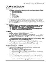
... analog functions • An OEM 5V supply for the DSP and UI systems. Most future upgrades can be accessed as the Mackie OS will likely fix the errors you are having, once the detected drive information is "System Error 43 - Also, it . Possible Solution: • Connect a keyboard and monitor and press F1 to the latest sotware version. However, because the drivers...
... analog functions • An OEM 5V supply for the DSP and UI systems. Most future upgrades can be accessed as the Mackie OS will likely fix the errors you are having, once the detected drive information is "System Error 43 - Also, it . Possible Solution: • Connect a keyboard and monitor and press F1 to the latest sotware version. However, because the drivers...
Service Manual
Page 37
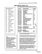
... 601- Switches 510- Fans 790- A-9 PARTS AC line cords 700- EPROM NOTE: Regarding console buttons. There is to replace whatever you have an angle or slope to each button, they are the older style, if they are taken directly from July 2001 Parts Numbering guide 040- Chassis Metalwork 600- Hardware 760- Capacitors 300- Fuses 550- Wires and Cables 640- Early models had flat buttons: 760...
... 601- Switches 510- Fans 790- A-9 PARTS AC line cords 700- EPROM NOTE: Regarding console buttons. There is to replace whatever you have an angle or slope to each button, they are the older style, if they are taken directly from July 2001 Parts Numbering guide 040- Chassis Metalwork 600- Hardware 760- Capacitors 300- Fuses 550- Wires and Cables 640- Early models had flat buttons: 760...
Service Manual
Page 68
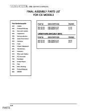
... CE D8B REMOTE CPU LATEST PARTS LISTS (JULY 2001) PART# DESCRIPTION 090-123-00 090-126-00 D8B CONSOLE CE D8B REMOTE CPU PAGES 41-42 43-45 PAGES 48-49 50-51 A-40 PARTS Finished PCB Assy 100- Jacks/Connectors 500- Chassis Metalwork 600- FINAL ASSEMBLY PARTS LIST FOR CE MODELS Parts Numbering guide 040- Capacitors 300- Semiconductors 400- Inductors 610- AC line cords...
... CE D8B REMOTE CPU LATEST PARTS LISTS (JULY 2001) PART# DESCRIPTION 090-123-00 090-126-00 D8B CONSOLE CE D8B REMOTE CPU PAGES 41-42 43-45 PAGES 48-49 50-51 A-40 PARTS Finished PCB Assy 100- Jacks/Connectors 500- Chassis Metalwork 600- FINAL ASSEMBLY PARTS LIST FOR CE MODELS Parts Numbering guide 040- Capacitors 300- Semiconductors 400- Inductors 610- AC line cords...


