Owners Manual
Page 2
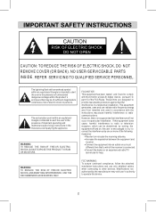
..., follow the attached installation instructions and use only shielded cables when connecting to radio or television reception, which the receiver is no guarantee that to part 15 of important operating and maintenance(servicing) instructions in a residential installation. NO USER-SERVICEABLE PARTS INSIDE. REFER SERVICING TO QUALIFIED SERVICE PERSONNEL. CAUTION RISK OF ELECTRIC SHOCK DO NOT OPEN CAUTION: TO REDUCE THE RISK OF ELECTRIC SHOCK, DO NOT REMOVE COVER (OR...
..., follow the attached installation instructions and use only shielded cables when connecting to radio or television reception, which the receiver is no guarantee that to part 15 of important operating and maintenance(servicing) instructions in a residential installation. NO USER-SERVICEABLE PARTS INSIDE. REFER SERVICING TO QUALIFIED SERVICE PERSONNEL. CAUTION RISK OF ELECTRIC SHOCK DO NOT OPEN CAUTION: TO REDUCE THE RISK OF ELECTRIC SHOCK, DO NOT REMOVE COVER (OR...
Owners Manual
Page 3
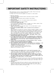
... adhered to. 8) Do not install near water and moisture, for replacement of the obsolete outlet . 10) Protect the power cord from being walked on a bed, sofa, rug or other source, refer to avoid injury from the type of time, unplug it is used, use this product from battery power, or other similar surface. Slots and openings in the cabinet and...
... adhered to. 8) Do not install near water and moisture, for replacement of the obsolete outlet . 10) Protect the power cord from being walked on a bed, sofa, rug or other source, refer to avoid injury from the type of time, unplug it is used, use this product from battery power, or other similar surface. Slots and openings in the cabinet and...

Owners Manual
Page 4
... to Provide some protection against voltage surges and built up static charges. a) When the power-supply cord or plug is provided to call the CATV system installer's attention to Article 820-40 of the NEC that provides guidelines for service. 25) Note to a wall or ceiling only as recommended by the operating instructions, as an adjustment of cable entry as close...
... to Provide some protection against voltage surges and built up static charges. a) When the power-supply cord or plug is provided to call the CATV system installer's attention to Article 820-40 of the NEC that provides guidelines for service. 25) Note to a wall or ceiling only as recommended by the operating instructions, as an adjustment of cable entry as close...
Owners Manual
Page 5
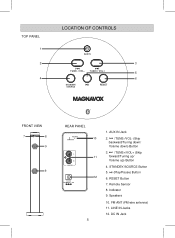
RESET Button 7. Remote Sensor 8. DC IN Jack STANDBY/SOURCE Button 5. (Play/Pause) Button 6. Speakers 10. Indicator 9. AUX IN Jack 2. /TUNE-/VOL- (Skip backward/Tuning down/ Volume down) Button 3. /TUNE+/VOL+ (Skip forward/Tuning up/ Volume up) Button 4. LINE IN Jacks 12. TOP PANEL 1 2 4 LOCATION OF CONTROLS AUX IN 3 TUNE- / VOL- TUNE+/ VOL+ 5 6 STANDBY/ SOURCE RESET FRONT VIEW 7 8 9 9 REAR PANEL FM ANT 10 L 11 R LINE IN DC IN DC 9V, 1.3A 12 5 1. FM ANT (FM wire antenna) 11.
RESET Button 7. Remote Sensor 8. DC IN Jack STANDBY/SOURCE Button 5. (Play/Pause) Button 6. Speakers 10. Indicator 9. AUX IN Jack 2. /TUNE-/VOL- (Skip backward/Tuning down/ Volume down) Button 3. /TUNE+/VOL+ (Skip forward/Tuning up/ Volume up) Button 4. LINE IN Jacks 12. TOP PANEL 1 2 4 LOCATION OF CONTROLS AUX IN 3 TUNE- / VOL- TUNE+/ VOL+ 5 6 STANDBY/ SOURCE RESET FRONT VIEW 7 8 9 9 REAR PANEL FM ANT 10 L 11 R LINE IN DC IN DC 9V, 1.3A 12 5 1. FM ANT (FM wire antenna) 11.

Owners Manual
Page 6
REMOTE CONTROL 1 RESET 1. /STANDBY Button 7 2 2. VOL- (Volume Down) Button TUNE+ 9 4. VOL+ (Volume Up) Button 9. /TUNE+ (Skip forward/ Tuning up) Button BATTERY INSTALLATION (REMOTE CONTROL) First Time Use: Remove and discard the insulation film as illustrated on the rear of the Remote Control as Fig.2 below . 2. Close the button cell holder as the polarity markings on the right. SOURCE Button 6 5. /TUNE- (Skip backward/ Tuning down Button 6. (Play/Pause) Button 7. (Mute) Button 8. Replace the button cell with a new CR2025 button cell as Fig.3 below : 1. If ...
REMOTE CONTROL 1 RESET 1. /STANDBY Button 7 2 2. VOL- (Volume Down) Button TUNE+ 9 4. VOL+ (Volume Up) Button 9. /TUNE+ (Skip forward/ Tuning up) Button BATTERY INSTALLATION (REMOTE CONTROL) First Time Use: Remove and discard the insulation film as illustrated on the rear of the Remote Control as Fig.2 below . 2. Close the button cell holder as the polarity markings on the right. SOURCE Button 6 5. /TUNE- (Skip backward/ Tuning down Button 6. (Play/Pause) Button 7. (Mute) Button 8. Replace the button cell with a new CR2025 button cell as Fig.3 below : 1. If ...
Owners Manual
Page 7
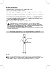
...installing the battery as indicated in the battery compartment. Keep new and used for a long period of time, remove the batteries to prevent damage or injury from possible battery leakage. 5. If you think batteries might have been swallowed or placed inside any other strong light shines on the REMOTE SENSOR of the unit, the operation...to the device. 3. Use only the size and type of the device prior to battery installation. 8. A reversed battery may not operate. If the batteries in just 2 hours and can overheat and rupture. (Follow battery manufacturer's instructions.) 6. it away ...
...installing the battery as indicated in the battery compartment. Keep new and used for a long period of time, remove the batteries to prevent damage or injury from possible battery leakage. 5. If you think batteries might have been swallowed or placed inside any other strong light shines on the REMOTE SENSOR of the unit, the operation...to the device. 3. Use only the size and type of the device prior to battery installation. 8. A reversed battery may not operate. If the batteries in just 2 hours and can overheat and rupture. (Follow battery manufacturer's instructions.) 6. it away ...
Owners Manual
Page 8
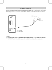
FM ANT AC/DC Adapter L R LINE IN To AC outlet DC IN DC 9V, 1.3A To the DC IN jack on the rear of unit then plug the AC/DC Adaptor to a wall outlet having AC 100-240V~; 50/60Hz. POWER SOURCE Connect the small plug from wall outlet. The AC/DC Adaptor is intended to be correctly orientated in a vertical or floor mount position. 8 The Red Standby Indicator on the top of unit will not use the unit for an extended period of time, unplug the AC/DC Adaptor from supplied AC/DC Adaptor to the DC IN Jack on the rear of the unit NOTES: If you will illuminate.
FM ANT AC/DC Adapter L R LINE IN To AC outlet DC IN DC 9V, 1.3A To the DC IN jack on the rear of unit then plug the AC/DC Adaptor to a wall outlet having AC 100-240V~; 50/60Hz. POWER SOURCE Connect the small plug from wall outlet. The AC/DC Adaptor is intended to be correctly orientated in a vertical or floor mount position. 8 The Red Standby Indicator on the top of unit will not use the unit for an extended period of time, unplug the AC/DC Adaptor from supplied AC/DC Adaptor to the DC IN Jack on the rear of the unit NOTES: If you will illuminate.
Owners Manual
Page 9
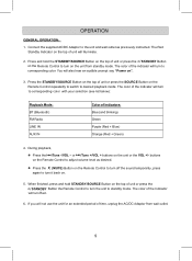
... to adjust volume level as previously instructed. The Red Standby Indicator on . 5. buttons on the Remote Control to turn on the unit from wall outlet. 9 When finished, press and hold the STANDBY/SOURCE Button on the top of unit or press the / STANDBY Button on the Remote Control to turn it back on the top of unit will also hear an audible prompt say "Power on the Remote Control repeatedly to switch to...
... to adjust volume level as previously instructed. The Red Standby Indicator on . 5. buttons on the Remote Control to turn on the unit from wall outlet. 9 When finished, press and hold the STANDBY/SOURCE Button on the top of unit or press the / STANDBY Button on the Remote Control to turn it back on the top of unit will also hear an audible prompt say "Power on the Remote Control repeatedly to switch to...
Owners Manual
Page 10
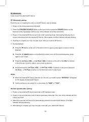
... the SOURCE Button on the display of the indicator turns Blue and blinks. 3. Power on the unit as previously instructed. If pairing is complete you may now play music with your external BT Device. 5. Power on the unit or press the /Tune - or /Tune +/VOL + buttons on the unit and enter to BT searching mode. Power on the Remote Control to turn off the sound temporary, press again to turn to...
... the SOURCE Button on the display of the indicator turns Blue and blinks. 3. Power on the unit as previously instructed. If pairing is complete you may now play music with your external BT Device. 5. Power on the unit or press the /Tune - or /Tune +/VOL + buttons on the unit and enter to BT searching mode. Power on the Remote Control to turn off the sound temporary, press again to turn to...
Owners Manual
Page 11
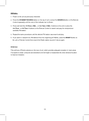
... play . 5. If you want to Green. 3. Power on the unit or Remote Control then search the Radio station as previously instructed. 2. Repeat the same procedures until the color of the indicator turn to research the FM stations from the beginning (87.5MHz), press the RESET Button on the unit as point 3 above again. FM Radio: 1. Press and hold the /Tune -/VOL - or /Tune +/VOL + buttons...
... play . 5. If you want to Green. 3. Power on the unit or Remote Control then search the Radio station as previously instructed. 2. Repeat the same procedures until the color of the indicator turn to research the FM stations from the beginning (87.5MHz), press the RESET Button on the unit as point 3 above again. FM Radio: 1. Press and hold the /Tune -/VOL - or /Tune +/VOL + buttons...
Owners Manual
Page 12
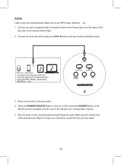
... supplied Audio Connection Cable to the Phones Jack; iPod/iPad ... etc) AUX IN TUNE- / VOL- Play the music on the connected external Audio Player as usual. (Make sure the volume level of unit as illustrated below: MP3 Player Mobile Phone Connect to the AUX IN Jack on the unit as an MP3 Player; TUNE+/ VOL+ STANDBY/ SOURCE RESET 3. Line Out Jack or AUX Out Jack on the Remote Control repeatedly until the color of the indicator turns Orange (Red + Green). 5. etc: 1. Connect...
... supplied Audio Connection Cable to the Phones Jack; iPod/iPad ... etc) AUX IN TUNE- / VOL- Play the music on the connected external Audio Player as usual. (Make sure the volume level of unit as illustrated below: MP3 Player Mobile Phone Connect to the AUX IN Jack on the unit as an MP3 Player; TUNE+/ VOL+ STANDBY/ SOURCE RESET 3. Line Out Jack or AUX Out Jack on the Remote Control repeatedly until the color of the indicator turns Orange (Red + Green). 5. etc: 1. Connect...

Owners Manual
Page 13
... turns Purple (Red + Blue). 5. Press the STANDBY/SOURCE Button on the top of unit or press the SOURCE Button on the Remote Control repeatedly until the color of RCA Connection Cable (not included) to the LINE IN Jacks on the unit as DVD Player/TV .... Power on the rear of unit as usual. (Make sure the volume level of TV/DVD player etc. 3. Play the video/music on the external Video/Audio Player. 2. Otherwise, sound from external Video/Audio Player such as instructed...
... turns Purple (Red + Blue). 5. Press the STANDBY/SOURCE Button on the top of unit or press the SOURCE Button on the Remote Control repeatedly until the color of RCA Connection Cable (not included) to the LINE IN Jacks on the unit as DVD Player/TV .... Power on the rear of unit as usual. (Make sure the volume level of TV/DVD player etc. 3. Play the video/music on the external Video/Audio Player. 2. Otherwise, sound from external Video/Audio Player such as instructed...
Owners Manual
Page 14
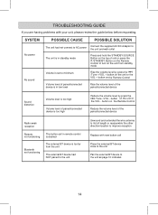
... wall outlet The unit is in standby mode Press and hold the STANDBY/SOURCE Button on the top of paired/connected device is too far from standby mode Volume is set to the unit as page 10 indicates 14 button on the Remote Control Reduce the volume level of the paired/connected device Radio weak reception Remote not functioning Bluetooth not functioning The button cell in low level Rise the volume level of the paired/connected device Sound distortion Volume level...
... wall outlet The unit is in standby mode Press and hold the STANDBY/SOURCE Button on the top of paired/connected device is too far from standby mode Volume is set to the unit as page 10 indicates 14 button on the Remote Control Reduce the volume level of the paired/connected device Radio weak reception Remote not functioning Bluetooth not functioning The button cell in low level Rise the volume level of the paired/connected device Sound distortion Volume level...
Owners Manual
Page 15
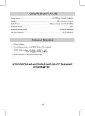
GENERAL SPECIFICATIONS Power source DC 9V,1300mA, Speaker 8W x 4ohm per channel Audio Power 5W per channel (Total 10 W, RMS) Bluetooth version...V4.1 Bluetooth working range 32 feet in open area FM radio frequency 87.5-108.0MHz PACKAGE INCLUDES: 1 x Owner's Manual 1 x Remote Control (Uses 1 x CR2025 Button Cell, included) 1 x AC/DC Adapter (Input: 100-240V~, 50/60Hz, 0.5A Output: 9V 1300mA ) 1 x Audio Connection Cable with 3.5mm plugs SPECIFICATIONS AND ACCESSORIES ARE SUBJECT TO CHANGE WITHOUT NOTICE 15
GENERAL SPECIFICATIONS Power source DC 9V,1300mA, Speaker 8W x 4ohm per channel Audio Power 5W per channel (Total 10 W, RMS) Bluetooth version...V4.1 Bluetooth working range 32 feet in open area FM radio frequency 87.5-108.0MHz PACKAGE INCLUDES: 1 x Owner's Manual 1 x Remote Control (Uses 1 x CR2025 Button Cell, included) 1 x AC/DC Adapter (Input: 100-240V~, 50/60Hz, 0.5A Output: 9V 1300mA ) 1 x Audio Connection Cable with 3.5mm plugs SPECIFICATIONS AND ACCESSORIES ARE SUBJECT TO CHANGE WITHOUT NOTICE 15


