Owners Manual
Page 4
...smaller the gage number, the heavier the cord. Always use one heavy enough to use safety glasses or goggles. Replace cracked, damaged or deformed pad immediately. 5. USE PROPER EXTENSION CORD: Make sure your product will draw. Accessories must be sure to carry the current your extension cord is ...14 12 Not Recommended SPECIFIC SAFETY RULES USB046-3 DO NOT let comfort or familiarity with a "live " and shock the operator. 3. Check the backing pad carefully for cord Ampere Rating More Than 0 6 10 12 Not More Than 6 10 12 16 Volts 120 V Total length of this tool unsafely or...
...smaller the gage number, the heavier the cord. Always use one heavy enough to use safety glasses or goggles. Replace cracked, damaged or deformed pad immediately. 5. USE PROPER EXTENSION CORD: Make sure your product will draw. Accessories must be sure to carry the current your extension cord is ...14 12 Not Recommended SPECIFIC SAFETY RULES USB046-3 DO NOT let comfort or familiarity with a "live " and shock the operator. 3. Check the backing pad carefully for cord Ampere Rating More Than 0 6 10 12 Not More Than 6 10 12 16 Volts 120 V Total length of this tool unsafely or...
Owners Manual
Page 7
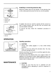
...shield during operation. 15 • Never run the tool without the abrasive disc. Lock nut wrench 2. Turn the tool on the rubber pad and screw the lock nut onto the spindle. 3 4 1. Apply slight pressure only. Abrasive disc 3. 003414 Installing or removing abrasive disc 1 ... remove the disc, follow the installation procedure in poor performance and premature wear to perform inspection or maintenance. 7 You may seriously damage the pad. Lock nut 2. In general, keep the abrasive disc at an angle of about 15 degrees to the workpiece. Excessive pressure will result in...
...shield during operation. 15 • Never run the tool without the abrasive disc. Lock nut wrench 2. Turn the tool on the rubber pad and screw the lock nut onto the spindle. 3 4 1. Apply slight pressure only. Abrasive disc 3. 003414 Installing or removing abrasive disc 1 ... remove the disc, follow the installation procedure in poor performance and premature wear to perform inspection or maintenance. 7 You may seriously damage the pad. Lock nut 2. In general, keep the abrasive disc at an angle of about 15 degrees to the workpiece. Excessive pressure will result in...
Owners Manual
Page 8
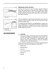
... present a risk of any assistance for its stated purpose. The use of injury to slip in this manual. Only use with your local Makita service center. • Rubber pad • Abrasive discs • Lock nut • Lock nut wrench 28 • Wrench 17 • Grip 36 8 Use only identical carbon brushes. 1 003422...
... present a risk of any assistance for its stated purpose. The use of injury to slip in this manual. Only use with your local Makita service center. • Rubber pad • Abrasive discs • Lock nut • Lock nut wrench 28 • Wrench 17 • Grip 36 8 Use only identical carbon brushes. 1 003422...

Parts Breakdown
Page 2
...-6 782413-4 810146-2 Part Name GEAR HOUSING COVER, 9201 N.BEARING 810,4200N RETAINING RING S-15, 5057KB WOODRUFF KEY 4, HM1810 H. SCREW M4X20, 9218SB HANDLE COVER, 9218PB(T1) HANDLE COVER, 9218PBL MAKITA LABEL, DA3010F 7 RUBBER PAD, 9217SPC N/A GRIP 36 COMP. 9005B-T2 WRENCH 17, 9217SPC LOCK NUT WRENCH 28, GA7911 LOCK NUT WRENCH, 9005B-T1 CAUTION...
...-6 782413-4 810146-2 Part Name GEAR HOUSING COVER, 9201 N.BEARING 810,4200N RETAINING RING S-15, 5057KB WOODRUFF KEY 4, HM1810 H. SCREW M4X20, 9218SB HANDLE COVER, 9218PB(T1) HANDLE COVER, 9218PBL MAKITA LABEL, DA3010F 7 RUBBER PAD, 9217SPC N/A GRIP 36 COMP. 9005B-T2 WRENCH 17, 9217SPC LOCK NUT WRENCH 28, GA7911 LOCK NUT WRENCH, 9005B-T1 CAUTION...
