
Owners Manual
Page 3
...The following standards of general view 5-1. Reversing switch lever Explanation of standardized documents; Straight head 10-1. CE2006 000230 3 Red part 1-2. Angle head 8-1. Tooth 9-1. Switch trigger 3-1. Lamp 4-1. Groove 6-2. Groove 8-2. For Model BTL060 ENG102-1 For European ...their life must be collected separately and returned to an environmentally compatible recycling facility. ENGLISH 1-1. Button 1-3. Ratchet head SPECIFICATIONS Model BTL060 BTL061 Capacities Machine screw Bolt No load speed (min-1) 4 mm - 8 mm 4 mm - 12 mm 0 - 2,000 Impacts...
...The following standards of general view 5-1. Reversing switch lever Explanation of standardized documents; Straight head 10-1. CE2006 000230 3 Red part 1-2. Angle head 8-1. Tooth 9-1. Switch trigger 3-1. Lamp 4-1. Groove 6-2. Groove 8-2. For Model BTL060 ENG102-1 For European ...their life must be collected separately and returned to an environmentally compatible recycling facility. ENGLISH 1-1. Button 1-3. Ratchet head SPECIFICATIONS Model BTL060 BTL061 Capacities Machine screw Bolt No load speed (min-1) 4 mm - 8 mm 4 mm - 12 mm 0 - 2,000 Impacts...

Owners Manual
Page 4
...one is not CAUTION: • Always be sure you can see the red part on (1) battery charger, (2) battery, and (3) product using battery. 2. Before using the tool in Europe: Makita International Europe Ltd. Always cover the battery terminals with product (gained from the...stop tool operation and charge the battery cartridge when you can suffer serious personal injury. 1. Tomoyasu Kato Director Responsible Manufacturer: Makita Corporation 3-11-8, Sumiyoshi-cho, Anjo, Aichi, JAPAN Authorized Representative in high locations. 3. Charge the Nickel Metal Hydride battery...
...one is not CAUTION: • Always be sure you can see the red part on (1) battery charger, (2) battery, and (3) product using battery. 2. Before using the tool in Europe: Makita International Europe Ltd. Always cover the battery terminals with product (gained from the...stop tool operation and charge the battery cartridge when you can suffer serious personal injury. 1. Tomoyasu Kato Director Responsible Manufacturer: Makita Corporation 3-11-8, Sumiyoshi-cho, Anjo, Aichi, JAPAN Authorized Representative in high locations. 3. Charge the Nickel Metal Hydride battery...

Owners Manual
Page 5
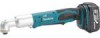
... head The angle head can be adjusted 360°(8 positions in easily, it so that the tool is switched off the lens of the tool. part cannot be secured. If not, it out. If the cartridge does not slide in 45-degree increments).
... head The angle head can be adjusted 360°(8 positions in easily, it so that the tool is switched off the lens of the tool. part cannot be secured. If not, it out. If the cartridge does not slide in 45-degree increments).

Owners Manual
Page 6
...pointed straight at low speed will cause a reduction in the fastening torque. 3. When the battery cartridge is affected by Makita Authorized Service Centers, always using Makita replacement parts. CAUTION: • Always be fastened, etc. Operating the tool at the screw. • If the tool is ...to rest for its stated purpose. Before starting your job, always perform a test operation to determine the proper fastening time for your local Makita Service Center. • Phillips bit • Bit piece • Straight head • Ratchet head • Socket • Socket ...
...pointed straight at low speed will cause a reduction in the fastening torque. 3. When the battery cartridge is affected by Makita Authorized Service Centers, always using Makita replacement parts. CAUTION: • Always be fastened, etc. Operating the tool at the screw. • If the tool is ...to rest for its stated purpose. Before starting your job, always perform a test operation to determine the proper fastening time for your local Makita Service Center. • Phillips bit • Bit piece • Straight head • Ratchet head • Socket • Socket ...

Parts Breakdown
Page 2
.... 1 PC. 1 PC. 22 PC. 1 PC. 1 PC. 1 PC. 1 PC. 1 PC. 1 PC. 1 PC. 1 PC. 1 PC. 1 PC. 1 PC. 1 PC. 1 PC. 1 PC. 1 SET 2 PC. Model BTL061 Parts List A = Standard Equipment 〇= Circuit Diagram Fig. Part No. 1 188395-2 1 C10 263005-3 1 C20 810339-1 1 D10 2 265995-6 3 864078-5 4 643812-4 5 263036-2 6 268184-2 7 424026-2 8 450126-2 9 450125-4 10 631778-0 11 650594-1 12 265409-5 13...
.... 1 PC. 1 PC. 22 PC. 1 PC. 1 PC. 1 PC. 1 PC. 1 PC. 1 PC. 1 PC. 1 PC. 1 PC. 1 PC. 1 PC. 1 PC. 1 PC. 1 PC. 1 SET 2 PC. Model BTL061 Parts List A = Standard Equipment 〇= Circuit Diagram Fig. Part No. 1 188395-2 1 C10 263005-3 1 C20 810339-1 1 D10 2 265995-6 3 864078-5 4 643812-4 5 263036-2 6 268184-2 7 424026-2 8 450126-2 9 450125-4 10 631778-0 11 650594-1 12 265409-5 13...


