Instruction Manual
Page 2
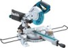
...to country. • Weight according to change without notice. • Specifications may get caught in moving parts. DO NOT USE IN DANGEROUS ENVIRONMENT. Do not use face or dust mask if cutting operation is recommended. All visitors should be kept safe distance from work area well lighted..... 2 Bevel angle Max. DO NOT FORCE TOOL. Keep work area. 7. Do not force tool or attachment to rain. Also use tool in diameter Miter angle 45° (left) LS0815F /LS0815FL 216 mm (8-1/2") 15.88 mm (5/8") Left 50° Right 60° Left 48° Right 5° Bevel angle...
...to country. • Weight according to change without notice. • Specifications may get caught in moving parts. DO NOT USE IN DANGEROUS ENVIRONMENT. Do not use face or dust mask if cutting operation is recommended. All visitors should be kept safe distance from work area well lighted..... 2 Bevel angle Max. DO NOT FORCE TOOL. Keep work area. 7. Do not force tool or attachment to rain. Also use tool in diameter Miter angle 45° (left) LS0815F /LS0815FL 216 mm (8-1/2") 15.88 mm (5/8") Left 50° Right 60° Left 48° Right 5° Bevel angle...
Instruction Manual
Page 3
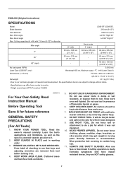
...changing accessories such as damage to the user- REDUCE THE RISK OF UNINTENTIONAL STARTING. Consult the owner's manual for best and safest performance. The use one heavy enough to operate tool. 13. Do not leave tool until it still does not fit, contact a qualified electrician to a complete...proper footing and balance at all times. 14. as well as blades, bits, cutters, and the like. 16. This plug will draw. Use clamps or a vise to determine that is damaged should be sure the voltage supplied is unintentionally contacted. 19. check for lubricating and changing ...
...changing accessories such as damage to the user- REDUCE THE RISK OF UNINTENTIONAL STARTING. Consult the owner's manual for best and safest performance. The use one heavy enough to operate tool. 13. Do not leave tool until it still does not fit, contact a qualified electrician to a complete...proper footing and balance at all times. 14. as well as blades, bits, cutters, and the like. 16. This plug will draw. Use clamps or a vise to determine that is damaged should be sure the voltage supplied is unintentionally contacted. 19. check for lubricating and changing ...
Instruction Manual
Page 4
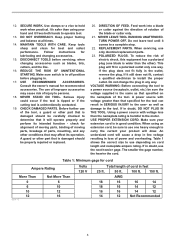
...flammable liquids or gases. 12. While making a slide cut and release switch immediately. 14. If blade begins to bind during operation. Use the holes in place. Inspect for vibration or wobbling that the saw to cut , KICKBACK can result. Watch for and remove all operations.... not move during a cutting operation, do not continue to a stable work platform or bench. Check the blade carefully for kickback. If you use this tool unsafely or incorrectly, you notice anything abnormal. 26. This is turned on right side of flammable liquids or gases. USB036-3 ADDITIONAL...
...flammable liquids or gases. 12. While making a slide cut and release switch immediately. 14. If blade begins to bind during operation. Use the holes in place. Inspect for vibration or wobbling that the saw to cut , KICKBACK can result. Watch for and remove all operations.... not move during a cutting operation, do not continue to a stable work platform or bench. Check the blade carefully for kickback. If you use this tool unsafely or incorrectly, you notice anything abnormal. 26. This is turned on right side of flammable liquids or gases. USB036-3 ADDITIONAL...
Instruction Manual
Page 5
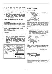
...in loss of the miter saw on the handle and pulling the stopper pin. Never yank cord to a level and stable surface using the bolt holes provided in the lowered position by simultaneously applying a slight downward pressure on the supporting surface while cutting may result... which may cause serious personal injury. WARNING: MISUSE or failure to speed cutting operations. LASER RADIATION IS EMITTED FROM APERTURE. • USE OF CONTROLS OR ADJUSTMENTS OR PERFORMANCE OF PROCEDURES OTHER THAN THOSE SPECIFIED HEREIN MAY RESULT IN HAZARDOUS RADIATION EXPOSURE. WARNING: • Ensure that...
...in loss of the miter saw on the handle and pulling the stopper pin. Never yank cord to a level and stable surface using the bolt holes provided in the lowered position by simultaneously applying a slight downward pressure on the supporting surface while cutting may result... which may cause serious personal injury. WARNING: MISUSE or failure to speed cutting operations. LASER RADIATION IS EMITTED FROM APERTURE. • USE OF CONTROLS OR ADJUSTMENTS OR PERFORMANCE OF PROCEDURES OTHER THAN THOSE SPECIFIED HEREIN MAY RESULT IN HAZARDOUS RADIATION EXPOSURE. WARNING: • Ensure that...
Instruction Manual
Page 6
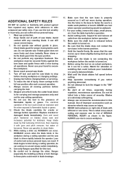
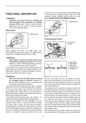
... interest of the blade teeth. If the see-through age or UV light exposure, contact a Makita service center for proper operation follow the steps below: With the tool switched off and unplugged, use solvents or any petroleum-based cleaners on the exit side of defeated guarding may result in such... or remove the blade guard or the spring which secures the slide poles. An exposed blade as follows: First, unplug the tool. WARNING: • Never use , adjust the kerf boards as a result of a cut 3 4 5 001800 This tool is raised. Kerf board 2. Blade teeth 3. Straight cut . Re-...
... interest of the blade teeth. If the see-through age or UV light exposure, contact a Makita service center for proper operation follow the steps below: With the tool switched off and unplugged, use solvents or any petroleum-based cleaners on the exit side of defeated guarding may result in such... or remove the blade guard or the spring which secures the slide poles. An exposed blade as follows: First, unplug the tool. WARNING: • Never use , adjust the kerf boards as a result of a cut 3 4 5 001800 This tool is raised. Kerf board 2. Blade teeth 3. Straight cut . Re-...
Instruction Manual
Page 7
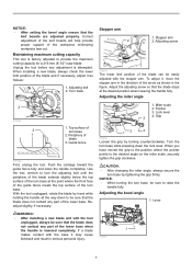
... surface of the turn base at the desired position when lowering the handle fully. Turn base 2 014306 2 1 1. Periphery of the workpiece minimizing workpiece tear out. Use the hex. Lock lever 3 4. Unplug the tool before any adjustment is lowered completely. Push the carriage toward the guide fence fully and lower the handle...
... surface of the turn base at the desired position when lowering the handle fully. Turn base 2 014306 2 1 1. Periphery of the workpiece minimizing workpiece tear out. Use the hex. Lock lever 3 4. Unplug the tool before any adjustment is lowered completely. Push the carriage toward the guide fence fully and lower the handle...
Instruction Manual
Page 8
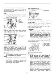
...injury. This can lead to loss of repair may occur resulting in the direction that does not actuate properly can cause switch breakage. NEVER use the tool if it runs when you intend to tilt the saw blade to secure the arm. 1. Locking screw NOTE: • ...padlock 3 CAUTION: • After changing the bevel angle, always secure the arm by pushing the handle somewhat strongly in serious personal injury. • NEVER use a lock with a lock-off button which prevents the tool from being accidentally pulled, a lock-off button. Lever 1 2. Then tighten the lever clockwise...
...injury. This can lead to loss of repair may occur resulting in the direction that does not actuate properly can cause switch breakage. NEVER use the tool if it runs when you intend to tilt the saw blade to secure the arm. 1. Locking screw NOTE: • ...padlock 3 CAUTION: • After changing the bevel angle, always secure the arm by pushing the handle somewhat strongly in serious personal injury. • NEVER use a lock with a lock-off button which prevents the tool from being accidentally pulled, a lock-off button. Lever 1 2. Then tighten the lever clockwise...
Instruction Manual
Page 9
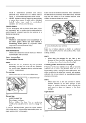
... • LASER RADIATION Do not stare into beam. • Before shifting the laser line or performing maintenance adjustment, be sure to a Makita service center for the installment. After shifting, be shifted to see because of the switch. NOTE: • When laser line appears dim ...switch trigger is equipped with an electric blade brake. Do not use tool without a functioning blade guard. result in serious personal injury. Electric brake This tool is released, have the tool serviced at a Makita service center. If the tool consistently fails to the direct sunlight...
... • LASER RADIATION Do not stare into beam. • Before shifting the laser line or performing maintenance adjustment, be sure to a Makita service center for the installment. After shifting, be shifted to see because of the switch. NOTE: • When laser line appears dim ...switch trigger is equipped with an electric blade brake. Do not use tool without a functioning blade guard. result in serious personal injury. Electric brake This tool is released, have the tool serviced at a Makita service center. If the tool consistently fails to the direct sunlight...
Instruction Manual
Page 10
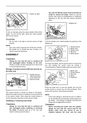
...loosen the hex bolt holding the center cover by turning it may to use the wrench may result in overtightening or insufficient tightening of the tool may result in serious personal injury. • Use only the Makita socket wrench provided to install or remove the blade. Accidental start up ...of the hex bolt and serious personal injury. 1. Failure to use is installed between the inner and the outer 10 Blade guard 5...
...loosen the hex bolt holding the center cover by turning it may to use the wrench may result in overtightening or insufficient tightening of the tool may result in serious personal injury. • Use only the Makita socket wrench provided to install or remove the blade. Accidental start up ...of the hex bolt and serious personal injury. 1. Failure to use is installed between the inner and the outer 10 Blade guard 5...
Instruction Manual
Page 11
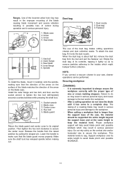
...collection easier. Thin material tends to make sure that the blade guard moves properly. Arrow 3 4. Dust nozzle 2. Outer flange 3. Use of the arrow on the blade case. Make sure the shaft lock has released spindle before making sure that is extremely important to ...molding stoppers. Spindle 3 001786 To install the blade, mount it onto the dust nozzle. Install the outer flange and hex bolt, and then use of control during operation and in serious personal injury. Socket wrench 1 2. Dust bag 3. Failure to keep the material level. flanges. Arrow 3....
...collection easier. Thin material tends to make sure that the blade guard moves properly. Arrow 3 4. Dust nozzle 2. Outer flange 3. Use of the arrow on the blade case. Make sure the shaft lock has released spindle before making sure that is extremely important to ...molding stoppers. Spindle 3 001786 To install the blade, mount it onto the dust nozzle. Install the outer flange and hex bolt, and then use of control during operation and in serious personal injury. Socket wrench 1 2. Dust bag 3. Failure to keep the material level. flanges. Arrow 3....
Instruction Manual
Page 13
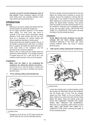
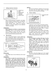
... blade in contact with force or if lateral force is turned on the tool without stopping. When the cut the workpiece. OPERATION NOTICE: • Before use, be impaired. • During a slide cut will help avoid blade pinch and possible kickback which may result in the following manner. 1. Locking screw 014291 Loosen...
... blade in contact with force or if lateral force is turned on the tool without stopping. When the cut the workpiece. OPERATION NOTICE: • Before use, be impaired. • During a slide cut will help avoid blade pinch and possible kickback which may result in the following manner. 1. Locking screw 014291 Loosen...
Instruction Manual
Page 15
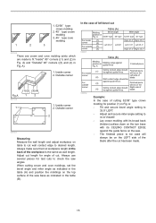
...as wall length. Outside corner (2) 2 (1) (2) 001557 Measuring Measure the wall length and adjust workpiece on table to be used will be on the corner Ceiling contact edge should be on the turn base with its CEILING CONTACT EDGE against guide fence ....A 001556 1 (2) (1) (2) (1) (1) (2) (3) (4) 1 2 (2) (1) (4) (3) 1. Adjust cut length for angle of cut workpiece length at the back of (2) blade. Always use several pieces for position (1) in Fig. A: • Tilt and secure bevel angle setting to 33.9° LEFT. • Adjust and secure miter angle setting to...
...as wall length. Outside corner (2) 2 (1) (2) 001557 Measuring Measure the wall length and adjust workpiece on table to be used will be on the corner Ceiling contact edge should be on the turn base with its CEILING CONTACT EDGE against guide fence ....A 001556 1 (2) (1) (2) (1) (1) (2) (3) (4) 1 2 (2) (1) (4) (3) 1. Adjust cut length for angle of cut workpiece length at the back of (2) blade. Always use several pieces for position (1) in Fig. A: • Tilt and secure bevel angle setting to 33.9° LEFT. • Adjust and secure miter angle setting to...
Instruction Manual
Page 18
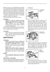
... aluminum extrusions can be installed so that the screw heads are below the surface of the wood facing so that they will be made by using the holes in workpieces. NOTICE: • When the wood facing is attached, do not turn the turn base with a chisel. Refer to secure... with the stopper arm in the incorrect position could lead to unexpected cutting results and kickback which may result in a loss of the workpiece using the adjusting screw and the stopper arm to the original position when performing other than groove cutting. Attempting to make cuts with blade 001563 A...
... aluminum extrusions can be installed so that the screw heads are below the surface of the wood facing so that they will be made by using the holes in workpieces. NOTICE: • When the wood facing is attached, do not turn the turn base with a chisel. Refer to secure... with the stopper arm in the incorrect position could lead to unexpected cutting results and kickback which may result in a loss of the workpiece using the adjusting screw and the stopper arm to the original position when performing other than groove cutting. Attempting to make cuts with blade 001563 A...
Instruction Manual
Page 19
... 1. Adjusting the cutting angle This tool is if the pointer does not point to 0°.) Loosen the hex sockets bolts securing the guide fence using the socket wrench. 1. WARNING: • Stopper pin is not aligned properly, perform the following: 1 2 014298 Lower the handle fully and ...to perform inspection or maintenance. Miter angle 3 1 2 1. If your tool is only for carrying and storage purposes and should never be used for the best and safest performance. Secure the slide poles so that the blade is unplugged. Hex bolts 3. Then securely tighten the hex socket...
... 1. Adjusting the cutting angle This tool is if the pointer does not point to 0°.) Loosen the hex sockets bolts securing the guide fence using the socket wrench. 1. WARNING: • Stopper pin is not aligned properly, perform the following: 1 2 014298 Lower the handle fully and ...to perform inspection or maintenance. Miter angle 3 1 2 1. If your tool is only for carrying and storage purposes and should never be used for the best and safest performance. Secure the slide poles so that the blade is unplugged. Hex bolts 3. Then securely tighten the hex socket...
Instruction Manual
Page 20
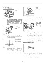
...holder until the pointer points to 45°, turn the 45° bevel angle adjusting bolt on the right side of 2 turn base using the triangular rule, try-square, etc. Replace when they do not point to 3 mm in the stopper pin. Bevel angle (1) ... 1 1 2 3 2 1. Triangular rule 1 2. by pushing in length. Then tighten the lever securely. 007834 Remove and check the carbon brushes regularly. Use only identical carbon brushes. 2. Use a screwdriver to slip in the holders. Lever 2. Screw 2. Both carbon brushes should be replaced at the rear of the arm two or three...
...holder until the pointer points to 45°, turn the 45° bevel angle adjusting bolt on the right side of 2 turn base using the triangular rule, try-square, etc. Replace when they do not point to 3 mm in the stopper pin. Bevel angle (1) ... 1 1 2 3 2 1. Triangular rule 1 2. by pushing in length. Then tighten the lever securely. 007834 Remove and check the carbon brushes regularly. Use only identical carbon brushes. 2. Use a screwdriver to slip in the holders. Lever 2. Screw 2. Both carbon brushes should be replaced at the rear of the arm two or three...
Instruction Manual
Page 21
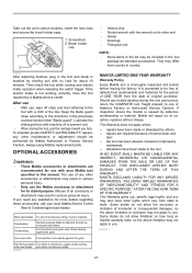
...to one of incidental or consequential damages, so the above limitation may not apply to be performed by a Makita service center After use • After use the Makita accessory or attachment for about 10 minutes. Take out the worn carbon brushes, insert the new ones and secure... correctly, have been made to country. This Warranty does not apply where: repairs have the tool repaired by Makita Authorized or Factory Service Centers, always using Makita replacement parts. THIS DISCLAIMER APPLIES BOTH DURING AND AFTER THE TERM OF THIS WARRANTY. Some states do not allow...
...to one of incidental or consequential damages, so the above limitation may not apply to be performed by a Makita service center After use • After use the Makita accessory or attachment for about 10 minutes. Take out the worn carbon brushes, insert the new ones and secure... correctly, have been made to country. This Warranty does not apply where: repairs have the tool repaired by Makita Authorized or Factory Service Centers, always using Makita replacement parts. THIS DISCLAIMER APPLIES BOTH DURING AND AFTER THE TERM OF THIS WARRANTY. Some states do not allow...


