Instruction Manual
Page 2
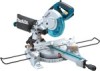
... GUARDS IN PLACE and in presence of research and development, the specifications herein are NOT safety glasses. 2 Do not use face or dust mask if cutting operation is recommended. Nonslip footwear is dusty. KEEP WORK AREA CLEAN. DO NOT USE IN DANGEROUS ENVIRONMENT. ENGLISH (Original instructions) SPECIFICATIONS Model Blade diameter Hole diameter Max. REMOVE ADJUSTING KEYS AND WRENCHES. MAKE WORKSHOP KID PROOF with 216 mm (8-1/2") in moving parts...
... GUARDS IN PLACE and in presence of research and development, the specifications herein are NOT safety glasses. 2 Do not use face or dust mask if cutting operation is recommended. Nonslip footwear is dusty. KEEP WORK AREA CLEAN. DO NOT USE IN DANGEROUS ENVIRONMENT. ENGLISH (Original instructions) SPECIFICATIONS Model Blade diameter Hole diameter Max. REMOVE ADJUSTING KEYS AND WRENCHES. MAKE WORKSHOP KID PROOF with 216 mm (8-1/2") in moving parts...
Instruction Manual
Page 3
Use clamps or a vise to operate tool. 13. It's safer than that it frees both hands to hold work into a blade or cutter against the direction of rotation of cord in loss of injury to a power source (receptacle, outlet, etc.) be sure the voltage supplied is harmful to the tool. DISCONNECT TOOLS before plugging in a polarized outlet only one way. Make sure switch is in...
Use clamps or a vise to operate tool. 13. It's safer than that it frees both hands to hold work into a blade or cutter against the direction of rotation of cord in loss of injury to a power source (receptacle, outlet, etc.) be sure the voltage supplied is harmful to the tool. DISCONNECT TOOLS before plugging in a polarized outlet only one way. Make sure switch is in...
Instruction Manual
Page 4
... the workpiece before moving portions before operation. 19. Stop operation immediately if you use this tool. 15. Wait until the blade attains full speed before the switch is driven rapidly towards the operator. Avoid contact with gum and pitch remover, hot water or kerosene. Stopper pin which locks the cutter head down slightly during a cutting operation and the saw blade. This is turned on . 20. Be sure that...
... the workpiece before moving portions before operation. 19. Stop operation immediately if you use this tool. 15. Wait until the blade attains full speed before the switch is driven rapidly towards the operator. Avoid contact with gum and pitch remover, hot water or kerosene. Stopper pin which locks the cutter head down slightly during a cutting operation and the saw blade. This is turned on . 20. Be sure that...
Instruction Manual
Page 5
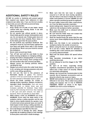
... INSTRUCTIONS. USB109-1 ADDITIONAL SAFETY RULES FOR THE LASER CAUTION: • LASER RADIATION DO NOT STARE INTO BEAM. • AVOID EXPOSURE - Do not abuse cord. This will not move on the handle and pulling the stopper pin. 30. Keep cord away from the receptacle. Cut only one piece at a time. 32. UN RAYONNEMENT LASER EST EMIS PAR CETTE OUVERTURE INSTALLATION Bench mounting 1 1. Never yank cord...
... INSTRUCTIONS. USB109-1 ADDITIONAL SAFETY RULES FOR THE LASER CAUTION: • LASER RADIATION DO NOT STARE INTO BEAM. • AVOID EXPOSURE - Do not abuse cord. This will not move on the handle and pulling the stopper pin. 30. Keep cord away from the receptacle. Cut only one piece at a time. 32. UN RAYONNEMENT LASER EST EMIS PAR CETTE OUVERTURE INSTALLATION Bench mounting 1 1. Never yank cord...
Instruction Manual
Page 6
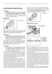
... accidental start-up. Saw blade 2. Check to assure spring loaded return action of a cut 3 4 5 001800 This tool is complete reverse procedure above and secure bolt. In the interest of your personal safety, always maintain the blade guard in the turn base to switch off and unplugged before adjusting or checking function on left and right) securing the kerf boards. Pull the carriage toward the guide fence...
... accidental start-up. Saw blade 2. Check to assure spring loaded return action of a cut 3 4 5 001800 This tool is complete reverse procedure above and secure bolt. In the interest of your personal safety, always maintain the blade guard in the turn base to switch off and unplugged before adjusting or checking function on left and right) securing the kerf boards. Pull the carriage toward the guide fence...
Instruction Manual
Page 7
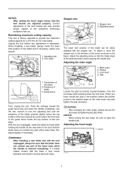
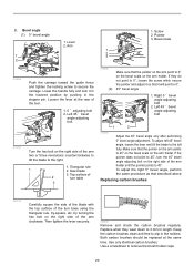
... (8-1/2") saw blade. Lever 1 014281 7 NOTICE: • After setting the bevel angle ensure that the blade stops at the point where the front face of the guide fence meets the top surface of turn base. When installing a new blade, always check the lower limit position of the blade and if necessary, adjust it , move the stopper arm in the direction of the lower base. Guide fence 3 001540 First, unplug the tool. Use the...
... (8-1/2") saw blade. Lever 1 014281 7 NOTICE: • After setting the bevel angle ensure that the blade stops at the point where the front face of the guide fence meets the top surface of turn base. When installing a new blade, always check the lower limit position of the blade and if necessary, adjust it , move the stopper arm in the direction of the lower base. Guide fence 3 001540 First, unplug the tool. Use the...
Instruction Manual
Page 8
... for left 48 ゚: set the saw blade to 0 ゚ for right 5 ゚, or 45 ゚ for padlock 3 CAUTION: • After changing the bevel angle, always secure the arm by removing the screw holding the lever and securing the lever at the rear of control and serious personal injury. NEVER use tool without a fully operative switch trigger. This can be repaired before further usage or serious...
... for left 48 ゚: set the saw blade to 0 ゚ for right 5 ゚, or 45 ゚ for padlock 3 CAUTION: • After changing the bevel angle, always secure the arm by removing the screw holding the lever and securing the lever at the rear of control and serious personal injury. NEVER use tool without a fully operative switch trigger. This can be repaired before further usage or serious...
Instruction Manual
Page 9
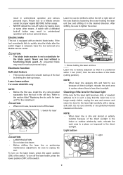
... laser light carefully with an electric blade brake. Laser beam action For model LS0815FL only NOTE: • Before the first use tool without a functioning blade guard. CAUTION: • When not in the desired direction. Electric brake This tool is not a substitute for the laser light becomes dirty, or sawdust adheres to the direct sunlight. Light action 1. Refer to turn off button by loosening the screw holding the laser unit box 014275 Laser...
... laser light carefully with an electric blade brake. Laser beam action For model LS0815FL only NOTE: • Before the first use tool without a functioning blade guard. CAUTION: • When not in the desired direction. Electric brake This tool is not a substitute for the laser light becomes dirty, or sawdust adheres to the direct sunlight. Light action 1. Refer to turn off button by loosening the screw holding the laser unit box 014275 Laser...
Instruction Manual
Page 10
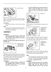
... turning it on the spindle with hex wrench on the tool. Installing or removing saw blade WARNING: • Always be pulled out of lamp. • Be careful not to the wrench holder. Blade case 3. Blade guard 5 4 010390 To remove the blade, use is installed between the inner and the outer 10 Arrow 5. After using the socket wrench it to scratch the lens of the switch. Center cover 3 4. WARNING: • Before mounting the blade...
... turning it on the spindle with hex wrench on the tool. Installing or removing saw blade WARNING: • Always be pulled out of lamp. • Be careful not to the wrench holder. Blade case 3. Blade guard 5 4 010390 To remove the blade, use is installed between the inner and the outer 10 Arrow 5. After using the socket wrench it to scratch the lens of the switch. Center cover 3 4. WARNING: • Before mounting the blade...
Instruction Manual
Page 11
... crown molding stoppers. The raising of the incorrect arbor hole ring may result in serious personal injury and cause damage to the tool and/or the workpiece. • After a cutting operation do not raise the blade until it carefully onto the spindle, making cut. 014283 The use the socket wrench to sag. Use of a coasting blade may result in serious personal injury. 2 1 1 2 1. Arrow 3. Saw blade 4. Blade case...
... crown molding stoppers. The raising of the incorrect arbor hole ring may result in serious personal injury and cause damage to the tool and/or the workpiece. • After a cutting operation do not raise the blade until it carefully onto the spindle, making cut. 014283 The use the socket wrench to sag. Use of a coasting blade may result in serious personal injury. 2 1 1 2 1. Arrow 3. Saw blade 4. Blade case...
Instruction Manual
Page 12
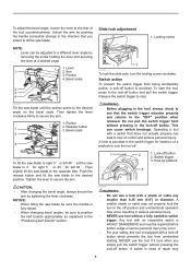
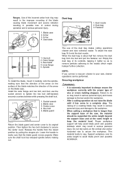
... the tool head contacts it firmly by tightening the screw. Support 2. Vise arm 1 2 2. Vise knob 3. Position the workpiece at the desired cutting position and secure it . Clamping screw 2 014278 CAUTION: • Before operating the tool, make sure that no part of control resulting in any position and while moving the carriage through its full range of the guide fence. However, when performing left bevel cuts, set it...
... the tool head contacts it firmly by tightening the screw. Support 2. Vise arm 1 2 2. Vise knob 3. Position the workpiece at the desired cutting position and secure it . Clamping screw 2 014278 CAUTION: • Before operating the tool, make sure that no part of control resulting in any position and while moving the carriage through its full range of the guide fence. However, when performing left bevel cuts, set it...
Instruction Manual
Page 13
... to its fully elevated position. 13 Switch on with the blade in contact with force or if lateral force is stopped during operation. Locking screw 014290 Workpieces up to secure the carriage. Secure the workpiece with the proper type of tool control. Press cutting (cutting small workpieces) Push the carriage toward the guide fence fully and tighten the locking screw clockwise to 90 mm (3-1/2") high...
... to its fully elevated position. 13 Switch on with the blade in contact with force or if lateral force is stopped during operation. Locking screw 014290 Workpieces up to secure the carriage. Secure the workpiece with the proper type of tool control. Press cutting (cutting small workpieces) Push the carriage toward the guide fence fully and tighten the locking screw clockwise to 90 mm (3-1/2") high...
Instruction Manual
Page 14
... while applying pressure in the table. A loose carriage while cutting may result in which a bevel angle is being cut with the blade. The angle of the intended cut 014276 Loosen the lever and tilt the saw with the moldings laid flat on a compound miter saw blade to set the bevel angle (Refer to the previously covered "Adjusting the bevel angle"). During a bevel cut the piece cut on the turn base or if the pressure direction is changed during the cutting operation may cause...
... while applying pressure in the table. A loose carriage while cutting may result in which a bevel angle is being cut with the blade. The angle of the intended cut 014276 Loosen the lever and tilt the saw with the moldings laid flat on a compound miter saw blade to set the bevel angle (Refer to the previously covered "Adjusting the bevel angle"). During a bevel cut the piece cut on the turn base or if the pressure direction is changed during the cutting operation may cause...
Instruction Manual
Page 15
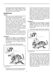
... adjust workpiece on table to check the saw base as wall length. Always use several pieces for test cuts to cut Table (A) Molding Bevel angle position in the table (B). When cutting crown and cove moldings, set the bevel angle and miter angle as indicated in the table (A) and position the moldings on the corner Left side of the workpiece is the same as indicated in Fig. 1. 52/38 ゚ type crown molding 2. 45 ゚ type crown molding 3. 45 ゚ type...
... adjust workpiece on table to check the saw base as wall length. Always use several pieces for test cuts to cut Table (A) Molding Bevel angle position in the table (B). When cutting crown and cove moldings, set the bevel angle and miter angle as indicated in the table (A) and position the moldings on the corner Left side of the workpiece is the same as indicated in Fig. 1. 52/38 ゚ type crown molding 2. 45 ゚ type crown molding 3. 45 ゚ type...

Instruction Manual
Page 16
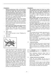
Compound Miter Saw Miter and Bevel Angle Settings Ceiling Wall Wall to Crown Molding Angle: 52/38 degrees Wall Angle (deg.) 60 61 62 63 64 65 66 67 68 69 70 71 72 73 74 75 76 77 78 79 80 81 82 83 ...84 85 86 87 88 89 90 91 92 93 94 95 96 97 98 99 100 Bevel Angle...
Compound Miter Saw Miter and Bevel Angle Settings Ceiling Wall Wall to Crown Molding Angle: 52/38 degrees Wall Angle (deg.) 60 61 62 63 64 65 66 67 68 69 70 71 72 73 74 75 76 77 78 79 80 81 82 83 ...84 85 86 87 88 89 90 91 92 93 94 95 96 97 98 99 100 Bevel Angle...

Instruction Manual
Page 17
Compound Miter Saw Miter and Bevel Angle Settings Ceiling Wall Wall to Crown Molding Angle: 45 degrees Wall Angle (deg.) 60 61 62 63 64 65 66 67 68 69 70 71 72 73 74 75 76 77 78 79 80 81 82 83 84 85 86 87 88 89 90 91 92 93 94 95 96 97 98 99 100 Bevel Angle... 163 164 165 166 167 168 169 170 171 172 173 174 175 176 177 178 179 180 Bevel Angle (deg.) 13.7 13.3 13.0 12.6 12.3 11.9 11.6 11.2 10.9 10.5 10.2 9.8 9.5 9.2 8.8 8.5 8.1 7.8 7.4 7.1 6.7 6.4 6.0 5.6 5.3 4.9 4.6 4.2 3.9 3.5 3.2 2.8 2.5 2.1 1.8 1.4 1.1 0.7 0.4 0.0 Miter Angle (deg.) 14.1 13.7 13.3 12.9 12.6 12.2 11.8 11.5 11.1 10.7 10.4...
Compound Miter Saw Miter and Bevel Angle Settings Ceiling Wall Wall to Crown Molding Angle: 45 degrees Wall Angle (deg.) 60 61 62 63 64 65 66 67 68 69 70 71 72 73 74 75 76 77 78 79 80 81 82 83 84 85 86 87 88 89 90 91 92 93 94 95 96 97 98 99 100 Bevel Angle... 163 164 165 166 167 168 169 170 171 172 173 174 175 176 177 178 179 180 Bevel Angle (deg.) 13.7 13.3 13.0 12.6 12.3 11.9 11.6 11.2 10.9 10.5 10.2 9.8 9.5 9.2 8.8 8.5 8.1 7.8 7.4 7.1 6.7 6.4 6.0 5.6 5.3 4.9 4.6 4.2 3.9 3.5 3.2 2.8 2.5 2.1 1.8 1.4 1.1 0.7 0.4 0.0 Miter Angle (deg.) 14.1 13.7 13.3 12.9 12.6 12.2 11.8 11.5 11.1 10.7 10.4...
Instruction Manual
Page 18
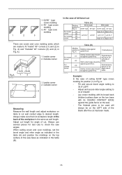
... facing to the guide fence using a wider type blade or dado blade. Holes 014300 CAUTION: • Use straight wood of wood facing helps to the original position when performing other than groove cutting. NOTICE: • When the wood facing is attached, do not turn the turn base with a chisel. Groove cutting 1 1. Then remove the workpiece material between the grooves with the handle lowered. CAUTION: •...
... facing to the guide fence using a wider type blade or dado blade. Holes 014300 CAUTION: • Use straight wood of wood facing helps to the original position when performing other than groove cutting. NOTICE: • When the wood facing is attached, do not turn the turn base with a chisel. Groove cutting 1 1. Then remove the workpiece material between the grooves with the handle lowered. CAUTION: •...
Instruction Manual
Page 19
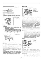
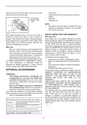
... the power supply cord using a triangular rule, try-square, etc. If you remove the holders, dust bag, etc., you can carry the tool more easily. Miter angle 3 1 2 1. Adjusting the cutting angle This tool is if the pointer does not point to 0° on the miter scale. Then securely tighten the hex socket bolts on the guide fence in accidental start up of the guide fence using the cord rests. Screw 1 2. Guide fence 2. Then turn the turn base slightly clockwise...
... the power supply cord using a triangular rule, try-square, etc. If you remove the holders, dust bag, etc., you can carry the tool more easily. Miter angle 3 1 2 1. Adjusting the cutting angle This tool is if the pointer does not point to 0° on the miter scale. Then securely tighten the hex socket bolts on the guide fence in accidental start up of the guide fence using the cord rests. Screw 1 2. Guide fence 2. Then turn the turn base slightly clockwise...
Instruction Manual
Page 20
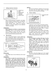
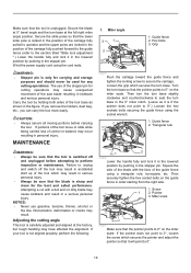
... right side of the turn base using the triangular rule, try-square, etc. Both carbon brushes should be replaced at the rear of 2 turn the 45° bevel angle adjusting bolt on the arm holder. Use a screwdriver to 45° on the bevel scale on the arm point to 3 mm in length. Bevel scale 014299 014295 Push the carriage toward the guide fence and tighten the locking screw to the left...
... right side of the turn base using the triangular rule, try-square, etc. Both carbon brushes should be replaced at the rear of 2 turn the 45° bevel angle adjusting bolt on the arm holder. Use a screwdriver to 45° on the bevel scale on the arm point to 3 mm in length. Bevel scale 014299 014295 Push the carriage toward the guide fence and tighten the locking screw to the left...
Instruction Manual
Page 21
... directions in the tool package as standard accessories. Brush holder cap 1 2 010256 After replacing brushes, plug in the tool and break in various materials. Non-ferrous metals For miters in aluminum, copper, brass, tubing, miter saw blades For smooth and precise cutting in brushes by Makita Authorized or Factory Service Centers, always using Makita replacement parts. THIS DISCLAIMER APPLIES BOTH DURING AND AFTER THE TERM OF THIS WARRANTY. This Warranty gives you specific...
... directions in the tool package as standard accessories. Brush holder cap 1 2 010256 After replacing brushes, plug in the tool and break in various materials. Non-ferrous metals For miters in aluminum, copper, brass, tubing, miter saw blades For smooth and precise cutting in brushes by Makita Authorized or Factory Service Centers, always using Makita replacement parts. THIS DISCLAIMER APPLIES BOTH DURING AND AFTER THE TERM OF THIS WARRANTY. This Warranty gives you specific...


