
Installation Guide
Page 2
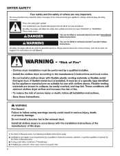
DRYER SAFETY 2
DRYER SAFETY 2

Installation Guide
Page 4
... connect to model) Parts supplied (steam models): "Y" connector Short inlet hose Rubber washer Parts package is located in ring terminals or spade terminals with clothes dryers. Parts needed for gas installations: Flat-blade screwdriver #2 Phillips screwdriver 8" (203 mm) or 10" (254 mm) pipe wrench 8" (203 mm) or 10" (254 mm) adjustable... installations) Tape measure Vent clamps Level Pliers Adjustable wrench that all models): or Leveling legs (4) (Length and appearance of legs may vary according to the dryer must end in...
... connect to model) Parts supplied (steam models): "Y" connector Short inlet hose Rubber washer Parts package is located in ring terminals or spade terminals with clothes dryers. Parts needed for gas installations: Flat-blade screwdriver #2 Phillips screwdriver 8" (203 mm) or 10" (254 mm) pipe wrench 8" (203 mm) or 10" (254 mm) adjustable... installations) Tape measure Vent clamps Level Pliers Adjustable wrench that all models): or Leveling legs (4) (Length and appearance of legs may vary according to the dryer must end in...

Installation Guide
Page 5
...short hose which are required. Location Requirements Installation clearances: For each arrangement, consider allowing more space for ease of 1" (25 mm) under entire dryer. You may use the water supply for your washer using power supply cord, a grounded electrical outlet located within 4 ft. (1.2 m) of the... enough to allow door to water, weather, or at temperatures below 45°F (7°C). IMPORTANT: Do not operate, install, or store dryer where it will need: ■■ A location allowing for walls, doors, and floor moldings. Optional Equipment: (Not supplied with maximum ...
...short hose which are required. Location Requirements Installation clearances: For each arrangement, consider allowing more space for ease of 1" (25 mm) under entire dryer. You may use the water supply for your washer using power supply cord, a grounded electrical outlet located within 4 ft. (1.2 m) of the... enough to allow door to water, weather, or at temperatures below 45°F (7°C). IMPORTANT: Do not operate, install, or store dryer where it will need: ■■ A location allowing for walls, doors, and floor moldings. Optional Equipment: (Not supplied with maximum ...

Installation Guide
Page 6
Additional installation requirements This dryer is available to the Manufactured Home Construction and Safety Standard, Title 24 CFR, Part 3280 (formerly the Federal Standard for Mobile Home Construction and Safety, ... allowed. ■■ Additional spacing should be considered. For further information, please reference the "Assistance or Service" section of the dryer is recommended to introduce outside air into the dryer. For gas dryers mobile home installations: ■■ Mobile Home Installation Hold-down Kit Part Number W10432680 is suitable for mobile home installations...
Additional installation requirements This dryer is available to the Manufactured Home Construction and Safety Standard, Title 24 CFR, Part 3280 (formerly the Federal Standard for Mobile Home Construction and Safety, ... allowed. ■■ Additional spacing should be considered. For further information, please reference the "Assistance or Service" section of the dryer is recommended to introduce outside air into the dryer. For gas dryers mobile home installations: ■■ Mobile Home Installation Hold-down Kit Part Number W10432680 is suitable for mobile home installations...
Installation Guide
Page 7
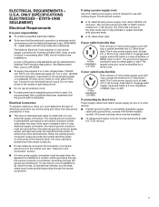
... removed from the external ground connector (green screw), and secured under the neutral terminal (center or white wire) of the terminal block, the dryer cabinet is adequate and in remodeling after 1996, and all local codes and ordinances. If your responsibility: ■■ To contact a qualified ...UL listed 30-amp power supply cord, rated 120/240 volt minimum. ELECTRICAL REQUIREMENTS - Connect to the neutral conductor (white wire) within the dryer. The kit should be type SRD or SRDT and be insulated. ■■ 10-gauge solid copper wire (do not permit the connection of...
... removed from the external ground connector (green screw), and secured under the neutral terminal (center or white wire) of the terminal block, the dryer cabinet is adequate and in remodeling after 1996, and all local codes and ordinances. If your responsibility: ■■ To contact a qualified ...UL listed 30-amp power supply cord, rated 120/240 volt minimum. ELECTRICAL REQUIREMENTS - Connect to the neutral conductor (white wire) within the dryer. The kit should be type SRD or SRDT and be insulated. ■■ 10-gauge solid copper wire (do not permit the connection of...

Installation Guide
Page 8
... proper outlet installed by providing a path of least resistance for electric current. Connect to an individual branch circuit. ■■ This dryer is equipped with Canadian Electrical Code, C22.1-latest edition and all local codes and ordinances. A time-delay fuse or circuit breaker is ...9632; To contact a qualified electrical installer. ■■ To be plugged into a standard 14-30R wall receptacle. It is within reach of dryer's final location. 4-wire receptacle (14-30R) ■■ 120 Volt, 60 Hz, AC only, 15- Check with all local codes. CANADA...
... proper outlet installed by providing a path of least resistance for electric current. Connect to an individual branch circuit. ■■ This dryer is equipped with Canadian Electrical Code, C22.1-latest edition and all local codes and ordinances. A time-delay fuse or circuit breaker is ...9632; To contact a qualified electrical installer. ■■ To be plugged into a standard 14-30R wall receptacle. It is within reach of dryer's final location. 4-wire receptacle (14-30R) ■■ 120 Volt, 60 Hz, AC only, 15- Check with all local codes. CANADA...

Installation Guide
Page 9
...tubing ■■ Must include 1/8" NPT minimum plugged tapping accessible for test gauge connection, immediately upstream of the gas connection to the dryer. ■■ 1/2" IPS pipe is recommended. ■■ 3/8" approved aluminum or copper tubing is acceptable for opening and closing ... gas company. Burner information is designcertified by CSA International for LP (propane or butane) gases with appropriate conversion. ■■ Your dryer must have a proper outlet installed by a quali ed electrician. In Canada: An individual manual shut-off valve must be used . ...
...tubing ■■ Must include 1/8" NPT minimum plugged tapping accessible for test gauge connection, immediately upstream of the gas connection to the dryer. ■■ 1/2" IPS pipe is recommended. ■■ 3/8" approved aluminum or copper tubing is acceptable for opening and closing ... gas company. Burner information is designcertified by CSA International for LP (propane or butane) gases with appropriate conversion. ■■ Your dryer must have a proper outlet installed by a quali ed electrician. In Canada: An individual manual shut-off valve must be used . ...

Installation Guide
Page 10
... legs GAS SUPPLY CONNECTION REQUIREMENTS ■ Use an elbow and a 3/8" flare x 3/8" NPT adapter fitting between the flexible gas connector and the dryer gas pipe, as needed, to flare adapter fitting C. 1/8" NPT minimum plugged tapping D. 1/2" NPT gas supply line E. Mobile home installations require ... E A B D A. 3/8" flexible gas connector B. 3/8" pipe to avoid kinking. ■ Use only pipe-joint compound. Prepare dryer for each 1,000 ft. (305 m) increase in leveling legs Dryer gas pipe or ■ The gas pipe that of foot is close to connect the exhaust vent. Firmly grasp...
... legs GAS SUPPLY CONNECTION REQUIREMENTS ■ Use an elbow and a 3/8" flare x 3/8" NPT adapter fitting between the flexible gas connector and the dryer gas pipe, as needed, to flare adapter fitting C. 1/8" NPT minimum plugged tapping D. 1/2" NPT gas supply line E. Mobile home installations require ... E A B D A. 3/8" flexible gas connector B. 3/8" pipe to avoid kinking. ■ Use only pipe-joint compound. Prepare dryer for each 1,000 ft. (305 m) increase in leveling legs Dryer gas pipe or ■ The gas pipe that of foot is close to connect the exhaust vent. Firmly grasp...
Installation Guide
Page 12
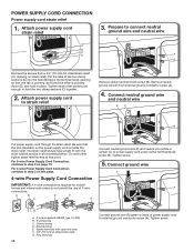
... supply cord through the strain relief. For 4-wire Power Supply Cord Connection, continue to hold in a horizontal position. Connect ground wire F A D. Spade terminals with the dryer cabinet and be in place. Tighten strain relief screws just enough to step 3 on page 13. Be sure that one tab is pointing up (A) and...
... supply cord through the strain relief. For 4-wire Power Supply Cord Connection, continue to hold in a horizontal position. Connect ground wire F A D. Spade terminals with the dryer cabinet and be in place. Tighten strain relief screws just enough to step 3 on page 13. Be sure that one tab is pointing up (A) and...

Installation Guide
Page 13
... block screw (B). 4. Ring terminals G. Connect neutral wire C B Connect neutral wire (white or center) (C) of the strain relief through the strain relief. Secure cover with the dryer cabinet and be in a horizontal position. Secure cover with upturned ends E. 3/4" (19 mm) UL listed strain relief F. Tighten screws. C. Spade terminals with hold -down screw...
... block screw (B). 4. Ring terminals G. Connect neutral wire C B Connect neutral wire (white or center) (C) of the strain relief through the strain relief. Secure cover with the dryer cabinet and be in a horizontal position. Secure cover with upturned ends E. 3/4" (19 mm) UL listed strain relief F. Tighten screws. C. Spade terminals with hold -down screw...

Installation Guide
Page 14
... wires to terminal block Connect neutral ground wire (E) and place hooked end (hook facing right) of neutral wire (white/center wire) (C) of extra length so dryer may be moved if needed. Tighten screw. 8. Squeeze hooked ends together and tighten screw. 7. Now, go to the right, squeeze hooked end together, and tighten...
... wires to terminal block Connect neutral ground wire (E) and place hooked end (hook facing right) of neutral wire (white/center wire) (C) of extra length so dryer may be moved if needed. Tighten screw. 8. Squeeze hooked ends together and tighten screw. 7. Now, go to the right, squeeze hooked end together, and tighten...

Installation Guide
Page 15
... to Venting Requirements. Squeeze hooked ends together and tighten screws. Optional 3-wire Connection You must have 5 ft. (1.52 m) of dryer rear panel. Shape wire ends into slot of extra length so dryer may be moved if needed. Tighten screw. 7. Place hooked ends of outer covering from external ground conductor screw (A). 15 Finally...
... to Venting Requirements. Squeeze hooked ends together and tighten screws. Optional 3-wire Connection You must have 5 ft. (1.52 m) of dryer rear panel. Shape wire ends into slot of extra length so dryer may be moved if needed. Tighten screw. 7. Place hooked ends of outer covering from external ground conductor screw (A). 15 Finally...

Installation Guide
Page 16
... ends of power supply cord or cable under outer terminal block screws (hooks facing right). A recommended connection is used to connect dryer to dryer Flared B maAle fitting mNoalne-fflBiattriendg Connect neutral ground wire (E) and neutral wire (white or center wire) (C) of remaining wires...existing gas line. Tighten screws. 4. Connect external ground wire GE A A. 3/8" flexible gas connector C. 3/8" to 3/8" pipe elbow B. 3/8" dryer pipe D. 3/8" pipe-to an adequate ground. Open shut-off valve Closed valve Open valve Connect a separate copper ground wire (G) from gas...
... ends of power supply cord or cable under outer terminal block screws (hooks facing right). A recommended connection is used to connect dryer to dryer Flared B maAle fitting mNoalne-fflBiattriendg Connect neutral ground wire (E) and neutral wire (white or center wire) (C) of remaining wires...existing gas line. Tighten screws. 4. Connect external ground wire GE A A. 3/8" flexible gas connector C. 3/8" to 3/8" pipe elbow B. 3/8" dryer pipe D. 3/8" pipe-to an adequate ground. Open shut-off valve Closed valve Open valve Connect a separate copper ground wire (G) from gas...

Installation Guide
Page 17
...than 90° elbows. Flexible metal vent: (Acceptable only if accessible to clean) ■■ Must be fully extended and supported in final dryer location. ■■ Remove excess to seal all governing codes and ordinances. Clamps: ■■ Use clamps to avoid sagging and kinking that... catch lint. VENTING Venting Requirements Exhaust hoods: ■■ Must be at least 12" (305 mm) from entire length of fire, this dryer MUST BE EXHAUSTED OUTDOORS. Rigid metal vent: ■■ Recommended for more information. 17 Replace plastic or metal foil vents with lint. See ...
...than 90° elbows. Flexible metal vent: (Acceptable only if accessible to clean) ■■ Must be fully extended and supported in final dryer location. ■■ Remove excess to seal all governing codes and ordinances. Clamps: ■■ Use clamps to avoid sagging and kinking that... catch lint. VENTING Venting Requirements Exhaust hoods: ■■ Must be at least 12" (305 mm) from entire length of fire, this dryer MUST BE EXHAUSTED OUTDOORS. Rigid metal vent: ■■ Recommended for more information. 17 Replace plastic or metal foil vents with lint. See ...

Installation Guide
Page 18
... exhaust installations Typical installations vent the dryer from the rear of the dryer. Clamps F. Select the type best for close -clearance installations are possible. Venting Kits For more information, call 1-800-688-2002 (Whirlpool and Maytag) or visit us at www.whirlpoolparts.ca (Whirlpool) or www.maytag.ca (Maytag). B C D A E F G B E H A. Elbow C. Rigid metal or flexible metal...
... exhaust installations Typical installations vent the dryer from the rear of the dryer. Clamps F. Select the type best for close -clearance installations are possible. Venting Kits For more information, call 1-800-688-2002 (Whirlpool and Maytag) or visit us at www.whirlpoolparts.ca (Whirlpool) or www.maytag.ca (Maytag). B C D A E F G B E H A. Elbow C. Rigid metal or flexible metal...

Installation Guide
Page 19
... around exhaust hood. 2. Avoid 90° turns. The "Vent System Chart" provides venting requirements that will : ■ Shorten life of dryer. ■ Reduce performance, resulting in "Vent System Chart." Determine vent length and elbows needed for mobile home installations: The exhaust vent must ...be securely fastened to dryer location using elbows or making turns, allow as much room as possible. ■ Bend vent gradually to avoid kinking. ■ ...
... around exhaust hood. 2. Avoid 90° turns. The "Vent System Chart" provides venting requirements that will : ■ Shorten life of dryer. ■ Reduce performance, resulting in "Vent System Chart." Determine vent length and elbows needed for mobile home installations: The exhaust vent must ...be securely fastened to dryer location using elbows or making turns, allow as much room as possible. ■ Bend vent gradually to avoid kinking. ■ ...
Installation Guide
Page 20
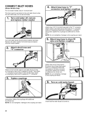
...by hand until it is seated on faucet. Check that the water faucet is seated on "Y" connector. 3. Damage to fill valve at top of dryer back panel. Screw on coupling by hand until it is turned on cold water faucet Using pliers, tighten the couplings with new rubber washer. 2. ... couplings 4" (101 mm) Attach other side of the 2 ft (0.6 m) inlet hose. NOTE: Do not overtighten. Turn on . 20 NOTE: Do not overtighten. The dryer must be connected to end of "Y" connector. Remove old rubber washer from inlet hose and replace with additional two-thirds turn.
...by hand until it is seated on faucet. Check that the water faucet is seated on "Y" connector. 3. Damage to fill valve at top of dryer back panel. Screw on coupling by hand until it is turned on cold water faucet Using pliers, tighten the couplings with new rubber washer. 2. ... couplings 4" (101 mm) Attach other side of the 2 ft (0.6 m) inlet hose. NOTE: Do not overtighten. Turn on . 20 NOTE: Do not overtighten. The dryer must be connected to end of "Y" connector. Remove old rubber washer from inlet hose and replace with additional two-thirds turn.

Installation Guide
Page 22
... to see whether gas supply line shut-off valve is open. ■ If the gas supply line shut-off valve is closed . ❑ When the dryer has been running for heat. If there is an extra part, go away. If you have all of hinges. 3. REVERSE DOOR SWING (OPTIONAL) NOTE: ...Magnetized screwdriver is first used. See "Level Dryer." ❑ Remove film on console and any tape remaining on a full heat cycle (not an air cycle) for certain part replacement or repair. Remove top...
... to see whether gas supply line shut-off valve is open. ■ If the gas supply line shut-off valve is closed . ❑ When the dryer has been running for heat. If there is an extra part, go away. If you have all of hinges. 3. REVERSE DOOR SWING (OPTIONAL) NOTE: ...Magnetized screwdriver is first used. See "Level Dryer." ❑ Remove film on console and any tape remaining on a full heat cycle (not an air cycle) for certain part replacement or repair. Remove top...

Installation Guide
Page 23
... seal or plastic door catches. 6. Switch door catch, bezel, and plug Flip door over Remove screws at the bottom of outer door and lift to dryer door so that hold the inner and outer door together. Reattach outer door panel to door. 5. NOTE: Do not pry apart with putty knife or... door hinges Catch and bezel Plug Remove the door catch, bezel, and plug from where they were. Place the door catch, bezel, and plug on dryer, grasp sides of the hinge. 23 Insert 4 door screws. 8.
... seal or plastic door catches. 6. Switch door catch, bezel, and plug Flip door over Remove screws at the bottom of outer door and lift to dryer door so that hold the inner and outer door together. Reattach outer door panel to door. 5. NOTE: Do not pry apart with putty knife or... door hinges Catch and bezel Plug Remove the door catch, bezel, and plug from where they were. Place the door catch, bezel, and plug on dryer, grasp sides of the hinge. 23 Insert 4 door screws. 8.
Installation Guide
Page 24
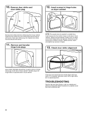
Remove door strike and door strike plug Door strike Door strike plug 12. Insert the door strike into the bottom holes on opposite side of dryer cabinet. Insert screws into door strike plug hole and secure with door catch. Slide door up so screws are in hinges. 13. Transfer plugs into... door strike aligns with screw. 10. Position door so large end of slots. Insert door strike plug into hinge holes on left side of dryer cabinet. TROUBLESHOOTING See the Use and Care Guide or visit our website and reference Frequently Asked Questions to gently remove 4 hinge hole plugs on...
Remove door strike and door strike plug Door strike Door strike plug 12. Insert the door strike into the bottom holes on opposite side of dryer cabinet. Insert screws into door strike plug hole and secure with door catch. Slide door up so screws are in hinges. 13. Transfer plugs into... door strike aligns with screw. 10. Position door so large end of slots. Insert door strike plug into hinge holes on left side of dryer cabinet. TROUBLESHOOTING See the Use and Care Guide or visit our website and reference Frequently Asked Questions to gently remove 4 hinge hole plugs on...


