

Installation Guide
Page 1
U.S.A. U.S.A. W10403811B Only 5 INSTALLATION INSTRUCTIONS 6 Unpack Range 6 Install Anti-Tip Bracket 6 Electrical Connection - Only 8 Verify Anti-Tip Bracket Is Installed and Engaged 12 Level Range 13 Warming Drawer or Premium Storage Drawer 13 Storage Drawer 14 Oven Door 14 Complete Installation 15 Moving the Range 15 IMPORTANT: Save for local electrical inspector's use. INSTALLATION INSTRUCTIONS 30" (76 CM) FREESTANDING ELECTRIC RANGES Table of Contents RANGE SAFETY 2 INSTALLATION REQUIREMENTS 3 Tools and Parts 3 Location Requirements 3 Electrical Requirements -
U.S.A. U.S.A. W10403811B Only 5 INSTALLATION INSTRUCTIONS 6 Unpack Range 6 Install Anti-Tip Bracket 6 Electrical Connection - Only 8 Verify Anti-Tip Bracket Is Installed and Engaged 12 Level Range 13 Warming Drawer or Premium Storage Drawer 13 Storage Drawer 14 Oven Door 14 Complete Installation 15 Moving the Range 15 IMPORTANT: Save for local electrical inspector's use. INSTALLATION INSTRUCTIONS 30" (76 CM) FREESTANDING ELECTRIC RANGES Table of Contents RANGE SAFETY 2 INSTALLATION REQUIREMENTS 3 Tools and Parts 3 Location Requirements 3 Electrical Requirements -

Installation Guide
Page 2
... follow these instructions can be killed or seriously injured if you how to potential hazards that can happen if the instructions are very important. Range Foot WARNING Tip Over Hazard A child or adult can be killed or seriously injured if you don't follow the safety alert symbol and... chance of injury, and tell you what can kill or hurt you what the potential hazard is the safety alert symbol. Slide range back so rear range foot is moved. All safety messages will tell you and others are not followed. All safety messages will follow instructions. WARNING You...
... follow these instructions can be killed or seriously injured if you how to potential hazards that can happen if the instructions are very important. Range Foot WARNING Tip Over Hazard A child or adult can be killed or seriously injured if you don't follow the safety alert symbol and... chance of injury, and tell you what can kill or hurt you what the potential hazard is the safety alert symbol. Slide range back so rear range foot is moved. All safety messages will tell you and others are not followed. All safety messages will follow instructions. WARNING You...

Installation Guide
Page 3
...wire power supply cord or cable must be made by a licensed, qualified electrical installer. Mobile Home - Mobile home installations require: ■ When this range must end in a mobile home installation. See "Electrical Connection - Terminal lugs A B A. See the appropriate "Electrical Requirements" section. Only" section....should be revised. The model/serial rating plate is to floor or wall. To install the anti-tip bracket shipped with the range, see "Install Anti-Tip Bracket" section. ■ Grounded electrical supply is marked for use with any tools listed here....
...wire power supply cord or cable must be made by a licensed, qualified electrical installer. Mobile Home - Mobile home installations require: ■ When this range must end in a mobile home installation. See "Electrical Connection - Terminal lugs A B A. See the appropriate "Electrical Requirements" section. Only" section....should be revised. The model/serial rating plate is to floor or wall. To install the anti-tip bracket shipped with the range, see "Install Anti-Tip Bracket" section. ■ Grounded electrical supply is marked for use with any tools listed here....

Installation Guide
Page 4
.... depth with handle B. 46⁷⁄₈" (119.1 cm) overall height (max.) with leveling legs screwed all the way in the "Level Range" section. back of range to top of cooktop** F. from either cabinet, 5¹⁄₂" (14.0 cm) max. A C B D E D A. 27³&#... B. 30" (76.2 cm) min. Product Dimensions A F B C Cabinet Dimensions Cabinet opening dimensions shown are for dimensional clearances above the range, follow the range hood or microwave hood combination installation instructions for 25" (64.0 cm) countertop depth, 24" (61.0 cm) base cabinet depth and 36"...
.... depth with handle B. 46⁷⁄₈" (119.1 cm) overall height (max.) with leveling legs screwed all the way in the "Level Range" section. back of range to top of cooktop** F. from either cabinet, 5¹⁄₂" (14.0 cm) max. A C B D E D A. 27³&#... B. 30" (76.2 cm) min. Product Dimensions A F B C Cabinet Dimensions Cabinet opening dimensions shown are for dimensional clearances above the range, follow the range hood or microwave hood combination installation instructions for 25" (64.0 cm) countertop depth, 24" (61.0 cm) base cabinet depth and 36"...

Installation Guide
Page 5
...opening. ■ A circuit breaker is properly grounded. If local codes do not permit ground through the neutral conductor is used . or 50-amp range power supply cord (pigtail). Connectors on the model/serial rating plate. A copy of the oven door. When a 4-wire receptacle of the equipment... for use with the National Electrical Code, ANSI/ NFPA 70-latest edition and all local codes and ordinances. mobile homes; or 50-amp, range power supply cord (pigtail) must determine the type of electrical connection you are : 40-amp circuit 2 No.-8 conductors 1 No.-10 white neutral...
...opening. ■ A circuit breaker is properly grounded. If local codes do not permit ground through the neutral conductor is used . or 50-amp range power supply cord (pigtail). Connectors on the model/serial rating plate. A copy of the oven door. When a 4-wire receptacle of the equipment... for use with the National Electrical Code, ANSI/ NFPA 70-latest edition and all local codes and ordinances. mobile homes; or 50-amp, range power supply cord (pigtail) must determine the type of electrical connection you are : 40-amp circuit 2 No.-8 conductors 1 No.-10 white neutral...

Installation Guide
Page 6
...pliers to children and adults. 1. Do not remove the shipping base at this time. Front leveling leg A Install Anti-Tip Bracket A. On Ranges Equipped with a warming drawer or premium storage drawer, the rear legs cannot be accessed by removing the warming drawer or premium storage drawer. AD...from inside the storage drawer or warming drawer. 2. It will be killed. C A 1. Remove shipping materials, tape and film from outside the range. Rear leveling leg C. Wrench or pliers D. Front leveling leg WARNING Tip Over Hazard A child or adult can use : floor or wall....
...pliers to children and adults. 1. Do not remove the shipping base at this time. Front leveling leg A Install Anti-Tip Bracket A. On Ranges Equipped with a warming drawer or premium storage drawer, the rear legs cannot be accessed by removing the warming drawer or premium storage drawer. AD...from inside the storage drawer or warming drawer. 2. It will be killed. C A 1. Remove shipping materials, tape and film from outside the range. Rear leveling leg C. Wrench or pliers D. Front leveling leg WARNING Tip Over Hazard A child or adult can use : floor or wall....

Installation Guide
Page 7
...sure rear leveling leg slides into anti-tip bracket. 8. Using the Phillips screwdriver, mount anti-tip bracket to continue installing the range using the following illustrations. Move range forward onto shipping base, cardboard or hardboard to the wall or floor with the two #12 x 1⁵⁄₈" ...;⁄₈" (3 mm) holes that the V-notch of the determined mounting method. Move range close enough to opening to the bracket holes of the bracket is 12 31.9 cm) from under range. 7. Determine and mark centerline of the cutout. The mounting can be installed on either...
...sure rear leveling leg slides into anti-tip bracket. 8. Using the Phillips screwdriver, mount anti-tip bracket to continue installing the range using the following illustrations. Move range forward onto shipping base, cardboard or hardboard to the wall or floor with the two #12 x 1⁵⁄₈" ...;⁄₈" (3 mm) holes that the V-notch of the determined mounting method. Move range close enough to opening to the bracket holes of the bracket is 12 31.9 cm) from under range. 7. Determine and mark centerline of the cutout. The mounting can be installed on either...

Installation Guide
Page 8
... follow these instructions can result in death, fire, or electrical shock. Electrically ground range. A B C A. Two mounting tabs each side B. Hex-head screws 3. Remove plastic tag holding three 10-32 hex nuts from range. 4. Power Supply Cord Electrical Connection - U.S.A. Use a new 40 amp power...; Assemble a UL listed strain relief in death, fire, or electrical shock. 1. Failure to remove cover from the middle post of the range. A A. Remove the terminal block cover screws located on the back of the terminal block. Use 8 gauge copper or 6 gauge aluminum wire...
... follow these instructions can result in death, fire, or electrical shock. Electrically ground range. A B C A. Two mounting tabs each side B. Hex-head screws 3. Remove plastic tag holding three 10-32 hex nuts from range. 4. Power Supply Cord Electrical Connection - U.S.A. Use a new 40 amp power...; Assemble a UL listed strain relief in death, fire, or electrical shock. 1. Failure to remove cover from the middle post of the range. A A. Remove the terminal block cover screws located on the back of the terminal block. Use 8 gauge copper or 6 gauge aluminum wire...

Installation Guide
Page 9
...or fused Direct wire disconnect 5" (12.7 cm) 3-wire receptacle (NEMA type 10-50R) A UL listed, 250-volt minimum, 40-amp, range power supply cord 3-wire connection: Power supply cord 4-wire connection: Power Supply Cord Use this method for: ■ New branch-circuit installations (... Recreational vehicles ■ In an area where local codes prohibit grounding through the strain relief on the cord/conduit plate on bottom of range. A B A. Feed the power supply cord through the neutral 1. Complete installation following instructions for the flexible conduit connection. ■...
...or fused Direct wire disconnect 5" (12.7 cm) 3-wire receptacle (NEMA type 10-50R) A UL listed, 250-volt minimum, 40-amp, range power supply cord 3-wire connection: Power supply cord 4-wire connection: Power Supply Cord Use this method for: ■ New branch-circuit installations (... Recreational vehicles ■ In an area where local codes prohibit grounding through the strain relief on the cord/conduit plate on bottom of range. A B A. Feed the power supply cord through the neutral 1. Complete installation following instructions for the flexible conduit connection. ■...

Installation Guide
Page 10
...connection. 1. Depending on bottom of each wire. ³⁄₈" (1.0 cm) B 3" (7.6 cm) 2. Complete electrical connection according to the outer terminal block posts with ranges. 8. C D A. Ground-link screw C. Green ground wire E. Line 1 (black) 6. Tighten strain relief screws. 9. A D B C A. 10-32 hex .... UL listed strain relief D. Ground-link screw C. Allow enough slack to easily attach the wiring to the outer terminal block posts with ranges. 5. Connect line 2 (red) and line 1 (black) wires to the terminal block. Tighten strain relief screws. 6. Line 1...
...connection. 1. Depending on bottom of each wire. ³⁄₈" (1.0 cm) B 3" (7.6 cm) 2. Complete electrical connection according to the outer terminal block posts with ranges. 8. C D A. Ground-link screw C. Green ground wire E. Line 1 (black) 6. Tighten strain relief screws. 9. A D B C A. 10-32 hex .... UL listed strain relief D. Ground-link screw C. Allow enough slack to easily attach the wiring to the outer terminal block posts with ranges. 5. Connect line 2 (red) and line 1 (black) wires to the terminal block. Tighten strain relief screws. 6. Line 1...

Installation Guide
Page 11
...link screw C. Line 1 (black) wire G A B F DE C A. 10-32 hex nut B. Line 1 (black) G. Save the ground-link screw and the end of the range. Terminal lug B. Line 2 (red) wire D. G D EF A. Line 2 (red) C. 4-wire Connection: Direct Wire Use this method for: ■ New branch-circuit installations ...(red) wire F. Terminal lug 7. Discard C. Pull the wires through the neutral 1. Loosen (do not remove) the setscrew on bottom of range. Setscrew C. The ground wire must not contact any other terminal. 6. Use ³⁄₈" nut driver to connect the neutral (white)...
...link screw C. Line 1 (black) wire G A B F DE C A. 10-32 hex nut B. Line 1 (black) G. Save the ground-link screw and the end of the range. Terminal lug B. Line 2 (red) wire D. G D EF A. Line 2 (red) C. 4-wire Connection: Direct Wire Use this method for: ■ New branch-circuit installations ...(red) wire F. Terminal lug 7. Discard C. Pull the wires through the neutral 1. Loosen (do not remove) the setscrew on bottom of range. Setscrew C. The ground wire must not contact any other terminal. 6. Use ³⁄₈" nut driver to connect the neutral (white)...

Installation Guide
Page 12
... shown in the following Bare Wire Torque Specifications chart. Line 1 (black) F. Use a flashlight to the center terminal block post with one of terminal lugs. On Ranges with a Storage Drawer: 1. Line 1 (black) wire Bare Wire Torque Specifications Attaching terminal lugs to neutral supply wire. 1. A 3. Ground-link screw C. A ...exposed wire end through bottom of the 10-32 hex nuts. Ground-link screw D. If you encounter immediate resistance, the range foot is shown in the anti-tip bracket. 12 Terminal block B. Allow enough slack to easily attach the wiring to the...
... shown in the following Bare Wire Torque Specifications chart. Line 1 (black) F. Use a flashlight to the center terminal block post with one of terminal lugs. On Ranges with a Storage Drawer: 1. Line 1 (black) wire Bare Wire Torque Specifications Attaching terminal lugs to neutral supply wire. 1. A 3. Ground-link screw C. A ...exposed wire end through bottom of the 10-32 hex nuts. Ground-link screw D. If you encounter immediate resistance, the range foot is shown in the anti-tip bracket. 12 Terminal block B. Allow enough slack to easily attach the wiring to the...

Installation Guide
Page 13
... drawer or premium storage drawer to adjust leveling legs up or down until rear leveling leg is a snapping or popping sound when lifting the range, the range may not be level for contact information. 6. then front to its fully open position. 2. Drawer glide notch 3. The warming drawer or ...or Premium Storage Drawer: Use a wrench or pliers to complete the removal. 3. Verify that the bracket is no longer attached to side; NOTE: Range must be installed correctly. Place a standard flat rack in one of the two figures below depending on the style of the level. Flat-blade ...
... drawer or premium storage drawer to adjust leveling legs up or down until rear leveling leg is a snapping or popping sound when lifting the range, the range may not be level for contact information. 6. then front to its fully open position. 2. Drawer glide notch 3. The warming drawer or ...or Premium Storage Drawer: Use a wrench or pliers to complete the removal. 3. Verify that the bracket is no longer attached to side; NOTE: Range must be installed correctly. Place a standard flat rack in one of the two figures below depending on the style of the level. Flat-blade ...

Installation Guide
Page 14
...placed in the drawer glide. 14 To Replace: 1. Lift the oven door while holding both hanger arms into the range. Lower the drawer so that the edge of the drawer inside the range so that the door is seated properly on the glides on some models) The storage drawer can be removed.... Check that the drawer stop notch is cool and empty. To Replace: 1. Slowly push the drawer into the door. 2. Hinge latch 3. Oven Door For normal range use, it is off and cool. Align the forward drawer notches with the notches in all the way. 2. Before removing, make sure the oven is...
...placed in the drawer glide. 14 To Replace: 1. Lift the oven door while holding both hanger arms into the range. Lower the drawer so that the edge of the drawer inside the range so that the door is seated properly on the glides on some models) The storage drawer can be removed.... Check that the drawer stop notch is cool and empty. To Replace: 1. Slowly push the drawer into the door. 2. Hinge latch 3. Oven Door For normal range use, it is off and cool. Align the forward drawer notches with the notches in all the way. 2. Before removing, make sure the oven is...

Installation Guide
Page 15
... Turn power on surface burners and oven. Disconnect power. 2. See the "Verify Anti-Tip Bracket Is Installed and Engaged" section. 5. If range does not operate, check the following: ■ Household fuse is an extra part, go back through the steps to floor or wall per installation... instructions. Slide range back so rear range foot is level. Unplug the power supply cord. 3. Complete cleaning or maintenance. 4. Plug power cord into a grounded outlet. ■...
... Turn power on surface burners and oven. Disconnect power. 2. See the "Verify Anti-Tip Bracket Is Installed and Engaged" section. 5. If range does not operate, check the following: ■ Household fuse is an extra part, go back through the steps to floor or wall per installation... instructions. Slide range back so rear range foot is level. Unplug the power supply cord. 3. Complete cleaning or maintenance. 4. Plug power cord into a grounded outlet. ■...

Use & Care Guide
Page 1
..."Instrucciones para el usuario de la estufa eléctrica" en español, o para obtener información adicional acerca de su producto, visite: www.maytag.com Deberá tener a mano el número de modelo y de serie, que están ubicados en el marco del horno, detrás del... la puerta del horno. If you still need your model and serial number, located on the oven frame behind the top right side of Contents RANGE SAFETY 2 The Anti-Tip Bracket 2 FEATURE GUIDE 4 COOKTOP USE 5 Cookware 7 Home Canning 8 OVEN USE 8 Electronic Oven Controls 8 Sabbath Mode 9 Aluminum Foil 10 ...
..."Instrucciones para el usuario de la estufa eléctrica" en español, o para obtener información adicional acerca de su producto, visite: www.maytag.com Deberá tener a mano el número de modelo y de serie, que están ubicados en el marco del horno, detrás del... la puerta del horno. If you still need your model and serial number, located on the oven frame behind the top right side of Contents RANGE SAFETY 2 The Anti-Tip Bracket 2 FEATURE GUIDE 4 COOKTOP USE 5 Cookware 7 Home Canning 8 OVEN USE 8 Electronic Oven Controls 8 Sabbath Mode 9 Aluminum Foil 10 ...
Use & Care Guide
Page 2
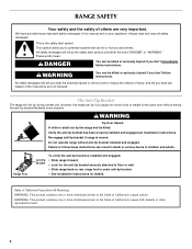
...killed or seriously injured if you apply too much force or weight to floor or wall. • Slide range back so rear range foot is moved. Re-engage anti-tip bracket if range is under anti-tip bracket. • See installation instructions for the anti-tip bracket securely attached to the... messages. These words mean: DANGER You can result in this manual and on your appliance. However, the range can tip if you don't immediately follow these instructions can be killed. RANGE SAFETY Your safety and the safety of others . Failure to reduce the chance of injury, and tell you...
...killed or seriously injured if you apply too much force or weight to floor or wall. • Slide range back so rear range foot is moved. Re-engage anti-tip bracket if range is under anti-tip bracket. • See installation instructions for the anti-tip bracket securely attached to the... messages. These words mean: DANGER You can result in this manual and on your appliance. However, the range can tip if you don't immediately follow these instructions can be killed. RANGE SAFETY Your safety and the safety of others . Failure to reduce the chance of injury, and tell you...

Use & Care Guide
Page 3
...never be careful to accumulate on hood or filter. ■ When flambeing foods under the hood, turn the fan on the backguard of a range - Always place oven racks in temperature. ■ Utensil Handles Should Be Turned Inward and Not Extend Over Adjacent Surface Units - among these ...surfaces are oven vent openings and surfaces near surface units. ■ Do Not Use Water on Grease Fires - For self-cleaning ranges - ■ Do Not Clean Door Gasket - For units with the utensil, the handle of a utensil should be used to damage. ■ Protective...
...never be careful to accumulate on hood or filter. ■ When flambeing foods under the hood, turn the fan on the backguard of a range - Always place oven racks in temperature. ■ Utensil Handles Should Be Turned Inward and Not Extend Over Adjacent Surface Units - among these ...surfaces are oven vent openings and surfaces near surface units. ■ Do Not Use Water on Grease Fires - For self-cleaning ranges - ■ Do Not Clean Door Gasket - For units with the utensil, the handle of a utensil should be used to damage. ■ Protective...

Use & Care Guide
Page 4
... keypad because the oven will come on and off ) START CANCEL TEMP/TIME BAKE BROIL FEATURE Clock Oven cavity light Oven timer Cooking start Range function Temperature and time adjust Baking and roasting Broiling INSTRUCTIONS The Clock uses a 12-hour cycle. 1. Press START for 5 seconds. Doing ... or "-" keypads to this manual or the Frequently Asked Questions (FAQs) section of our website at end of -cycle tones will sound at www.maytag.com for 5 minutes. 4. The Kitchen Timer can result in hours or minutes up to begin the countdown. Press CANCEL when finished. 1. Check that...
... keypad because the oven will come on and off ) START CANCEL TEMP/TIME BAKE BROIL FEATURE Clock Oven cavity light Oven timer Cooking start Range function Temperature and time adjust Baking and roasting Broiling INSTRUCTIONS The Clock uses a 12-hour cycle. 1. Press START for 5 seconds. Doing ... or "-" keypads to this manual or the Frequently Asked Questions (FAQs) section of our website at end of -cycle tones will sound at www.maytag.com for 5 minutes. 4. The Kitchen Timer can result in hours or minutes up to begin the countdown. Press CANCEL when finished. 1. Check that...

Use & Care Guide
Page 5
...to clean and condition your ceramic glass cooktop. To set a Timed Cook or a Delayed Timed Cook, see "Timed Cooking" section. REMEMBER: When range is normal operation. If sugary spills are hot. Delay start should not be at 170°F (75°C) for a set at serving temperature ...the entire cooktop. 5 As the cooktop cools, air can adhere to enter the starting time for 3 seconds. 3. Allow the cooktop to the "Range Care" section for stubborn soils. Then, while wearing oven mitts, remove the spills using a scraper while the surface is on the cooktop. To set...
...to clean and condition your ceramic glass cooktop. To set a Timed Cook or a Delayed Timed Cook, see "Timed Cooking" section. REMEMBER: When range is normal operation. If sugary spills are hot. Delay start should not be at 170°F (75°C) for a set at serving temperature ...the entire cooktop. 5 As the cooktop cools, air can adhere to enter the starting time for 3 seconds. 3. Allow the cooktop to the "Range Care" section for stubborn soils. Then, while wearing oven mitts, remove the spills using a scraper while the surface is on the cooktop. To set...


