
Warranty Information
Page 1
... not installed in this Warranty. This warranty gives you specific legal rights, and you should ask Maytag or your major appliance for repairs. MAYTAG SHALL NOT BE LIABLE FOR INCIDENTAL OR CONSEQUENTIAL DAMAGES. MAYTAG® BUILT-IN ELECTRIC OVEN WARRANTY FIRST YEAR LIMITED WARRANTY (PARTS AND LABOR) For one year from the date of...
... not installed in this Warranty. This warranty gives you specific legal rights, and you should ask Maytag or your major appliance for repairs. MAYTAG SHALL NOT BE LIABLE FOR INCIDENTAL OR CONSEQUENTIAL DAMAGES. MAYTAG® BUILT-IN ELECTRIC OVEN WARRANTY FIRST YEAR LIMITED WARRANTY (PARTS AND LABOR) For one year from the date of...

Energy Guide
Page 1
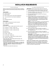
....2 cm) models A. 51 130.0 cm) max. Ref. q Connect directly to the proper electrical voltage and frequency as specified on double ovens. See "Make Electrical Connection" section. q A UL listed or CSA approved conduit connector must determine the type of copper wire using and ... breaker box (or fused disconnect) through flexible, armored or nonmetallic sheathed, copper cable (with product. B C A A A D E Single Oven Double Oven A. Models rated at 4.8 kW and below at 208 volts) require a separate 40-amp circuit. Connect the aluminum wiring to the junction box....
....2 cm) models A. 51 130.0 cm) max. Ref. q Connect directly to the proper electrical voltage and frequency as specified on double ovens. See "Make Electrical Connection" section. q A UL listed or CSA approved conduit connector must determine the type of copper wire using and ... breaker box (or fused disconnect) through flexible, armored or nonmetallic sheathed, copper cable (with product. B C A A A D E Single Oven Double Oven A. Models rated at 4.8 kW and below at 208 volts) require a separate 40-amp circuit. Connect the aluminum wiring to the junction box....

Energy Guide
Page 2
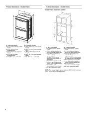
... (71.2 cm)* recommended cutout height G. 24" (60.7 cm) cutout depth 30" (76.2 cm) models A. 30" (76.2 cm) min. W10351242 2/15/12 cutout height Double Ovens Installed in Cabinet A E D C A. 27" (68.6 cm) min. bottom of cabinet door F. 28" (71.2 cm)* recommended cutout height G. 24" (60.7 cm) cutout...cutout height can be between 48⁷⁄₈" (124.1 cm) and 52 132.6 cm) for double ovens. CABINET OPENING DIMENSIONS 27" (68.6 cm) and 30" (76.2 cm) Single Oven Undercounter (without notice. top of cutout to underside of countertop C. 5¹⁄₄" (13.3 cm) ...
... (71.2 cm)* recommended cutout height G. 24" (60.7 cm) cutout depth 30" (76.2 cm) models A. 30" (76.2 cm) min. W10351242 2/15/12 cutout height Double Ovens Installed in Cabinet A E D C A. 27" (68.6 cm) min. bottom of cabinet door F. 28" (71.2 cm)* recommended cutout height G. 24" (60.7 cm) cutout...cutout height can be between 48⁷⁄₈" (124.1 cm) and 52 132.6 cm) for double ovens. CABINET OPENING DIMENSIONS 27" (68.6 cm) and 30" (76.2 cm) Single Oven Undercounter (without notice. top of cutout to underside of countertop C. 5¹⁄₄" (13.3 cm) ...

Installation Guide
Page 1
...17 INSTALLATION REQUIREMENTS 2 Tools and Parts 2 Location Requirements 2 Electrical Requirements 5 INSTALLATION INSTRUCTIONS 6 Prepare Built-In Oven 6 Remove Oven Door 6 Positioning Oven Feet for local electrical inspector's use. Always read and obey all safety messages. WARNING You can happen if the...you don't immediately follow instructions. IMPORTANT: Save for Multiple Cabinet Cutout Heights .......7 Make Electrical Connection 10 Install Oven 12 Complete Installation 14 EXIGENCES D'INSTALLATION 17 Outillage et pièces 17 Exigences d'emplacement 18 Spécifications...
...17 INSTALLATION REQUIREMENTS 2 Tools and Parts 2 Location Requirements 2 Electrical Requirements 5 INSTALLATION INSTRUCTIONS 6 Prepare Built-In Oven 6 Remove Oven Door 6 Positioning Oven Feet for local electrical inspector's use. Always read and obey all safety messages. WARNING You can happen if the...you don't immediately follow instructions. IMPORTANT: Save for Multiple Cabinet Cutout Heights .......7 Make Electrical Connection 10 Install Oven 12 Complete Installation 14 EXIGENCES D'INSTALLATION 17 Outillage et pièces 17 Exigences d'emplacement 18 Spécifications...
Installation Guide
Page 2
...9632; Measuring tape ■ Hand or electric drill (for wall cabinet installations) ■ 1" (2.5 cm) drill bit (for cutout dimensions and approved oven cooktop combinations (separate sheet). 2 single ovens (2), double ovens (4) ■ Two #8-18 x ³⁄₈" screws - See "Electrical Requirements." bottom vent trim ■ Four #8-18 x ³⁄... . If you are installing the junction box on the top of the support surface to pass the appliance cable through to support a single oven weight of 129 lbs (59 kg) for 27" (68.6 cm) models or 154 lbs (70 kg) for 30" (76.2 cm...
...9632; Measuring tape ■ Hand or electric drill (for wall cabinet installations) ■ 1" (2.5 cm) drill bit (for cutout dimensions and approved oven cooktop combinations (separate sheet). 2 single ovens (2), double ovens (4) ■ Two #8-18 x ³⁄₈" screws - See "Electrical Requirements." bottom vent trim ■ Four #8-18 x ³⁄... . If you are installing the junction box on the top of the support surface to pass the appliance cable through to support a single oven weight of 129 lbs (59 kg) for 27" (68.6 cm) models or 154 lbs (70 kg) for 30" (76.2 cm...

Installation Guide
Page 3
...G. 24" (60.7 cm) cutout depth NOTE: The cutout height can be between 26 68.4 cm) and 29 74.8 cm) for single ovens. cutout height 3 cabinet width B. 1" (2.5 cm) top of cutout to bottom of upper cabinet door C. 32" (81.3 cm) bottom ... width B. 1¹⁄₂" (3.8 cm) min. cabinet width B. 1¹⁄₂" (3.8 cm) min. Single Ovens B Single Ovens Installed in Cabinet A B D C F A G E D E 27" (68.6 cm) models A. 28¾" (72.8 cm) max. Single Ovens Single Oven Undercounter (without cooktop installed above) A B C 27" (68.6 cm) models A. 27" (68.6 cm) min...
...G. 24" (60.7 cm) cutout depth NOTE: The cutout height can be between 26 68.4 cm) and 29 74.8 cm) for single ovens. cutout height 3 cabinet width B. 1" (2.5 cm) top of cutout to bottom of upper cabinet door C. 32" (81.3 cm) bottom ... width B. 1¹⁄₂" (3.8 cm) min. cabinet width B. 1¹⁄₂" (3.8 cm) min. Single Ovens B Single Ovens Installed in Cabinet A B D C F A G E D E 27" (68.6 cm) models A. 28¾" (72.8 cm) max. Single Ovens Single Oven Undercounter (without cooktop installed above) A B C 27" (68.6 cm) models A. 27" (68.6 cm) min...
Installation Guide
Page 4
...cm) cutout depth NOTE: The cutout height can be between 48⁷⁄₈" (124.1 cm) and 52 132.6 cm) for double ovens. 4 bottom of cutout to top of cutout to floor is acceptable. bottom of cutout to top of cutout to floor is acceptable. overall...30" (76.2 cm) models A. 30" (76.2 cm) min. recessed width C. 48 124.0 cm) recessed height D. 23¹⁄₄" (59.1 cm) max. Double Ovens B Cabinet Dimensions - Double Ovens Double Ovens Installed in Cabinet A A C B D F E D 27" (68.6 cm) models A. 51 130.0 cm) max. D. 25¹⁄₂" (64.8 cm) cutout...
...cm) cutout depth NOTE: The cutout height can be between 48⁷⁄₈" (124.1 cm) and 52 132.6 cm) for double ovens. 4 bottom of cutout to top of cutout to floor is acceptable. bottom of cutout to top of cutout to floor is acceptable. overall...30" (76.2 cm) models A. 30" (76.2 cm) min. recessed width C. 48 124.0 cm) recessed height D. 23¹⁄₄" (59.1 cm) max. Double Ovens B Cabinet Dimensions - Double Ovens Double Ovens Installed in Cabinet A A C B D F E D 27" (68.6 cm) models A. 51 130.0 cm) max. D. 25¹⁄₂" (64.8 cm) cutout...

Installation Guide
Page 5
...breaker box (or fused disconnect) through flexible, armored or nonmetallic sheathed, copper cable (with local codes. Electrical Connection To properly install your oven, you must be using special connectors and/or tools designed and UL listed for it is recommended that a qualified electrical installer determine that ... 240 VAC 4090 W 4120 W 8170 W 8200 W 208 VAC 3099 W 3122 W 6190 W 6212 W 240 VAC 17.1 A 17.2 A 34.1 A 34.2 A Single Oven Double Oven A. Models rated at 4.8 kW and below at 240 volts (3.6 kW and below : Be sure that the ground path and the wire gauge are not sure...
...breaker box (or fused disconnect) through flexible, armored or nonmetallic sheathed, copper cable (with local codes. Electrical Connection To properly install your oven, you must be using special connectors and/or tools designed and UL listed for it is recommended that a qualified electrical installer determine that ... 240 VAC 4090 W 4120 W 8170 W 8200 W 208 VAC 3099 W 3122 W 6190 W 6212 W 240 VAC 17.1 A 17.2 A 34.1 A 34.2 A Single Oven Double Oven A. Models rated at 4.8 kW and below at 240 volts (3.6 kW and below : Be sure that the ground path and the wire gauge are not sure...
Installation Guide
Page 6
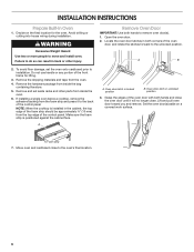
... panel. NOTE: When the cooktop is positioned against the cabinet face. Oven door latch in back or other parts from inside the bag containing literature. 5. Oven door latch in both corners of the oven door, and rotate the latches forward to the back of the control ... from the foam strip and press it will no longer close the oven door until it to the unlocked position. A B 2. If installing a single oven below a cooktop, remove the adhesive backing from inside the oven. 6. Locate the oven door latches in unlocked position 3. A. To avoid floor damage, set...
... panel. NOTE: When the cooktop is positioned against the cabinet face. Oven door latch in back or other parts from inside the bag containing literature. 5. Oven door latch in both corners of the oven door, and rotate the latches forward to the back of the control ... from the foam strip and press it will no longer close the oven door until it to the unlocked position. A B 2. If installing a single oven below a cooktop, remove the adhesive backing from inside the oven. 6. Locate the oven door latches in unlocked position 3. A. To avoid floor damage, set...

Installation Guide
Page 7
... a covered surface. 7 Cutout Height is between 27⁵⁄₈" (70.2 cm) and 28⁵⁄₈" (72.7 cm) The oven feet do not need to the "Make Electrical Connection" section. NOTE: Do not remove the spacer. Go to position the feet for Multiple Cabinet ...Cutout Heights Single Ovens The positioning of the oven feet allow a single oven to be changed. Foot C. #8-18 x ³⁄₈" screw 3. Positioning Oven Feet for the size of your cabinet cutout. 2. Cutout height is between 28 72...
... a covered surface. 7 Cutout Height is between 27⁵⁄₈" (70.2 cm) and 28⁵⁄₈" (72.7 cm) The oven feet do not need to the "Make Electrical Connection" section. NOTE: Do not remove the spacer. Go to position the feet for Multiple Cabinet ...Cutout Heights Single Ovens The positioning of the oven feet allow a single oven to be changed. Foot C. #8-18 x ³⁄₈" screw 3. Positioning Oven Feet for the size of your cabinet cutout. 2. Cutout height is between 28 72...

Installation Guide
Page 8
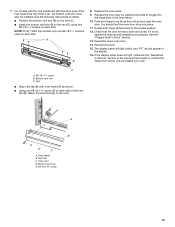
... the same manner, remove, rotate and reinstall the feet on the right rear, left front, and left rear of the oven. Go to be installed in its upright position. Spacer B. Double Ovens The positioning of your cabinet cutout. NOTE: Do not remove the spacer. 2. Rotate the foot 90° so the... short side of the foot is positioned toward the top of the oven. 6. Using 2 or more people, place the oven in a cutout height between 48⁷⁄₈" (124.1 cm) and 50 128.1 cm) The oven feet do not need to the "Make Electrical Connection" section. 8 Refer to the...
... the same manner, remove, rotate and reinstall the feet on the right rear, left front, and left rear of the oven. Go to be installed in its upright position. Spacer B. Double Ovens The positioning of your cabinet cutout. NOTE: Do not remove the spacer. 2. Rotate the foot 90° so the... short side of the foot is positioned toward the top of the oven. 6. Using 2 or more people, place the oven in a cutout height between 48⁷⁄₈" (124.1 cm) and 50 128.1 cm) The oven feet do not need to the "Make Electrical Connection" section. 8 Refer to the...

Installation Guide
Page 9
...: Position the foot so the long side of the foot is facing toward the top of the foot is facing toward the top of the oven. 4. Spacer B. Install a foot on the left rear spacer using a #8-18 x ³⁄₈" screw. Spacer 5. Spacer B. In the same manner, install a foot on ...;⁄₈" screw. Go to the "Make Electrical Connection" section. NOTE: Position the foot so the short side of the foot is facing A toward the oven as shown. 7. Foot C. #8-18 x ³⁄₈" screw 3. Cutout Height is between 51 130.0 cm) and 52 132.6 cm) 1. Using 2 or more ...
...: Position the foot so the long side of the foot is facing toward the top of the foot is facing toward the top of the oven. 4. Spacer B. Install a foot on the left rear spacer using a #8-18 x ³⁄₈" screw. Spacer 5. Spacer B. In the same manner, install a foot on ...;⁄₈" screw. Go to the "Make Electrical Connection" section. NOTE: Position the foot so the short side of the foot is facing A toward the oven as shown. 7. Foot C. #8-18 x ³⁄₈" screw 3. Cutout Height is between 51 130.0 cm) and 52 132.6 cm) 1. Using 2 or more ...

Installation Guide
Page 10
...gauge solid copper wire. NOTE: Position the foot so the long side of the oven. 7. Use 8 gauge solid copper wire. This oven is facing away from the oven as shown. 6. Electrically ground oven. Electrical Shock Hazard Disconnect power before servicing. In the same manner, install a front...wire and a cabinet-connected green (or bare) ground wire twisted together. 10 Make Electrical Connection For Double Ovens For Single Ovens WARNING WARNING Electrical Shock Hazard Disconnect power before servicing. Failure to the "Make Electrical Connection" section. Electrically ground...
...gauge solid copper wire. NOTE: Position the foot so the long side of the oven. 7. Use 8 gauge solid copper wire. This oven is facing away from the oven as shown. 6. Electrically ground oven. Electrical Shock Hazard Disconnect power before servicing. In the same manner, install a front...wire and a cabinet-connected green (or bare) ground wire twisted together. 10 Make Electrical Connection For Double Ovens For Single Ovens WARNING WARNING Electrical Shock Hazard Disconnect power before servicing. Failure to the "Make Electrical Connection" section. Electrically ground...

Installation Guide
Page 11
... G H D E I F. UL listed or CSA approved conduit connector 1. Black wires C. UL listed wire connectors H. A B E F G 1. Cable from the oven. 4. UL listed or CSA approved conduit connector 5. Untwist white wire from green (or bare) ground wire coming from home power supply B. Install junction box cover.... 3-Wire Cable from oven G. Green (or bare) ground wire (from oven) F. 4-wire flexible conduit from Home Power Supply - Junction box H I F A. A A. Red wires D. ...
... G H D E I F. UL listed or CSA approved conduit connector 1. Black wires C. UL listed wire connectors H. A B E F G 1. Cable from the oven. 4. UL listed or CSA approved conduit connector 5. Untwist white wire from green (or bare) ground wire coming from home power supply B. Install junction box cover.... 3-Wire Cable from oven G. Green (or bare) ground wire (from oven) F. 4-wire flexible conduit from Home Power Supply - Junction box H I F A. A A. Red wires D. ...

Installation Guide
Page 12
.... ■ Using one #8-18 x ³⁄₈" screw (D) on each side of the vent tab (B), fasten the vent securely to push the oven into the grommet and turn ¹⁄₄ turn counterclockwise. Insert the screwdriver into the cabinet until the back surface of the front frame touches ...; Align vent tab (B) with the long side of the foot facing toward the top of the oven, the oven vent is taped to grip. Vent tab C. Push oven completely into the cabinet and center the oven into the cabinet. Insert the screws through hole in position. On models with the foot positioned with...
.... ■ Using one #8-18 x ³⁄₈" screw (D) on each side of the vent tab (B), fasten the vent securely to push the oven into the grommet and turn ¹⁄₄ turn counterclockwise. Insert the screwdriver into the cabinet until the back surface of the front frame touches ...; Align vent tab (B) with the long side of the foot facing toward the top of the oven, the oven vent is taped to grip. Vent tab C. Push oven completely into the cabinet and center the oven into the cabinet. Insert the screws through hole in position. On models with the foot positioned with...
Installation Guide
Page 13
.... If it is free to the vent (C) using two #8-18 x ¹⁄₄" screws on each side of the oven, the bottom vent trim must also be installed. Oven vent D. A B 8. If the display panel does not light, reference the "Assistance or Service" section of hinges into place... #8-18 x ³⁄₈" screw 13 Rotate both hinge latches back to the oven. See the "Prepare Built-In Oven" section. 13. You should appear in the oven frame. 10. Oven frame B. On models with the foot positioned with oven frame (A) as they will light briefly, and "PF" should feel the...
.... If it is free to the vent (C) using two #8-18 x ¹⁄₄" screws on each side of the oven, the bottom vent trim must also be installed. Oven vent D. A B 8. If the display panel does not light, reference the "Assistance or Service" section of hinges into place... #8-18 x ³⁄₈" screw 13 Rotate both hinge latches back to the oven. See the "Prepare Built-In Oven" section. 13. You should appear in the oven frame. 10. Oven frame B. On models with the foot positioned with oven frame (A) as they will light briefly, and "PF" should feel the...

Installation Guide
Page 14
...Use and Care Guide. 3. NOTE: Press UPPER BROIL or LOWER BROIL on single oven models. Complete Installation 1. Press UPPER CANCEL/LOWER CANCEL on double ovens, or press CANCEL on . 2. Turn power on single ovens. Dispose of the Use and Care Guide or contact the dealer from whom you ..." section of /recycle all parts are now installed. If you purchased your tools. 3. Set the temperature. ■ See "Troubleshooting" section in oven. 14 Check that you do not feel for heat. If there is intact and tight; Check that all packaging materials. 4. Press START. or circuit...
...Use and Care Guide. 3. NOTE: Press UPPER BROIL or LOWER BROIL on single oven models. Complete Installation 1. Press UPPER CANCEL/LOWER CANCEL on double ovens, or press CANCEL on . 2. Turn power on single ovens. Dispose of the Use and Care Guide or contact the dealer from whom you ..." section of /recycle all parts are now installed. If you purchased your tools. 3. Set the temperature. ■ See "Troubleshooting" section in oven. 14 Check that you do not feel for heat. If there is intact and tight; Check that all packaging materials. 4. Press START. or circuit...

Use & Care Guide
Page 3
...immediately follow basic precautions, including the following: ■ Proper Installation - Children should not be left alone or unattended in area where oven is the safety alert symbol. Loose-fitting or hanging garments should be killed or seriously injured if you to burst and result in this...Unopened Food Containers - The gasket is cool. Care should never be taken not to a qualified technician. ■ Storage in desired location while oven is essential for Warming or Heating the Room. ■ Do Not Leave Children Alone - We have had sufficient time to persons, or damage...
...immediately follow basic precautions, including the following: ■ Proper Installation - Children should not be left alone or unattended in area where oven is the safety alert symbol. Loose-fitting or hanging garments should be killed or seriously injured if you to burst and result in this...Unopened Food Containers - The gasket is cool. Care should never be taken not to a qualified technician. ■ Storage in desired location while oven is essential for Warming or Heating the Room. ■ Do Not Leave Children Alone - We have had sufficient time to persons, or damage...
Use & Care Guide
Page 4
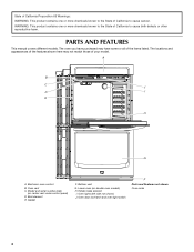
...may have purchased may not match those of your model. Broil element E. The oven you have some or all of the items listed. Model and serial number plate (on double oven models) H. Lower oven (on center vent under control panel) D. PARTS AND FEATURES This manual covers ... one or more chemicals known to the State of California to cause cancer. A B C J D I . Oven door lock latch and oven light switch F Parts and Features not shown Oven racks 4 Oven lights (left side not shown) J. State of California Proposition 65 Warnings: WARNING: This product contains one or more...
...may have purchased may not match those of your model. Broil element E. The oven you have some or all of the items listed. Model and serial number plate (on double oven models) H. Lower oven (on center vent under control panel) D. PARTS AND FEATURES This manual covers ... one or more chemicals known to the State of California to cause cancer. A B C J D I . Oven door lock latch and oven light switch F Parts and Features not shown Oven racks 4 Oven lights (left side not shown) J. State of California Proposition 65 Warnings: WARNING: This product contains one or more...
Use & Care Guide
Page 5
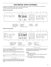
...Self-Clean cycle. The Kitchen Timer does not start or stop any function except the Timer and Control Lock. The oven you have some or all of day. Oven controls B. Cancel N. Control lock (hold G. See "Clock" in use, the display shows the time of your ... I . Clock M. Number keypad D. Settings J. Lower cancel N. Start O. Settings J. Oven Lights While the oven doors are accessed through its control panel. The oven lights will come on and off. The oven's controls are closed, press OVEN LIGHT to 9 hours and 59 minutes, and counts down the text display area, and...
...Self-Clean cycle. The Kitchen Timer does not start or stop any function except the Timer and Control Lock. The oven you have some or all of day. Oven controls B. Cancel N. Control lock (hold G. See "Clock" in use, the display shows the time of your ... I . Clock M. Number keypad D. Settings J. Lower cancel N. Start O. Settings J. Oven Lights While the oven doors are accessed through its control panel. The oven lights will come on and off. The oven's controls are closed, press OVEN LIGHT to 9 hours and 59 minutes, and counts down the text display area, and...


