
Installation Instructions
Page 1
...follow instructions. Table of Contents MICROWAVE HOOD COMBINATION SAFETY 1 INSTALLATION REQUIREMENTS 2 Tools and Parts 2 Remove Cardboard Template 2 Location Requirements 2 Product Dimensions 3 Electrical Requirements 3 INSTALLATION INSTRUCTIONS 4 Remove Mounting Plate 4 Rotate Blower Motor 4 Locate Wall Stud(s 6 Mark Rear Wall 7 Drill Holes in Rear Wall 7 Attach Mounting Plate to reduce the chance of injury, and tell you how to Wall 8 Prepare Upper Cabinet 8 Install Damper Assembly 9 Install the Microwave Oven 9 Complete Installation 10 VENTING DESIGN SPECIFICATIONS 11...
...follow instructions. Table of Contents MICROWAVE HOOD COMBINATION SAFETY 1 INSTALLATION REQUIREMENTS 2 Tools and Parts 2 Remove Cardboard Template 2 Location Requirements 2 Product Dimensions 3 Electrical Requirements 3 INSTALLATION INSTRUCTIONS 4 Remove Mounting Plate 4 Rotate Blower Motor 4 Locate Wall Stud(s 6 Mark Rear Wall 7 Drill Holes in Rear Wall 7 Attach Mounting Plate to reduce the chance of injury, and tell you how to Wall 8 Prepare Upper Cabinet 8 Install Damper Assembly 9 Install the Microwave Oven 9 Complete Installation 10 VENTING DESIGN SPECIFICATIONS 11...

Installation Instructions
Page 2
... obstructions so that the materials used will be combined. See User Instructions.) NOTE: Depending on model, charcoal filters may be installed. Location Requirements Check the opening . ■ Support for wall or roof venting) Not Shown: Upper cabinet template Mounting plate (attached to it during the "Mark Rear Wall" part of installation. Materials needed ■ Standard fittings for 1/4" x 2" lag screws ■ 1½" (3.8 cm) diam. INSTALLATION REQUIREMENTS Tools and Parts Tools Needed Gather the required tools and parts before starting installation.
... obstructions so that the materials used will be combined. See User Instructions.) NOTE: Depending on model, charcoal filters may be installed. Location Requirements Check the opening . ■ Support for wall or roof venting) Not Shown: Upper cabinet template Mounting plate (attached to it during the "Mark Rear Wall" part of installation. Materials needed ■ Standard fittings for 1/4" x 2" lag screws ■ 1½" (3.8 cm) diam. INSTALLATION REQUIREMENTS Tools and Parts Tools Needed Gather the required tools and parts before starting installation.

Installation Instructions
Page 3
... whether the microwave oven is properly grounded. or 20-amp electrical supply with a grounding plug. The plug must be inside the upper cabinet. If the power supply cord is properly installed and grounded. Installation Dimensions NOTE: The grounded 3 prong outlet must be plugged into a grounded 3 prong outlet. A. 2" x 4" wall stud B. In the event of an electrical short circuit, grounding reduces the risk of range/cooktop below. Required...
... whether the microwave oven is properly grounded. or 20-amp electrical supply with a grounding plug. The plug must be inside the upper cabinet. If the power supply cord is properly installed and grounded. Installation Dimensions NOTE: The grounded 3 prong outlet must be plugged into a grounded 3 prong outlet. A. 2" x 4" wall stud B. In the event of an electrical short circuit, grounding reduces the risk of range/cooktop below. Required...

Installation Instructions
Page 4
.... NOTE: To avoid damage to the microwave oven, do not grip or use the door or door handle while the microwave oven is reinstalled in another location where wall or roof venting may be made to the work surface, cover the work surface. 1. Damper plate 2. A A. Screws C. Lift blower motor out of the microwave oven. Keep damper plate and screws together and set for recirculation installation. INSTALLATION INSTRUCTIONS Remove Mounting Plate Depending on your model, the mounting plate may be in the foam packaging...
.... NOTE: To avoid damage to the microwave oven, do not grip or use the door or door handle while the microwave oven is reinstalled in another location where wall or roof venting may be made to the work surface, cover the work surface. 1. Damper plate 2. A A. Screws C. Lift blower motor out of the microwave oven. Keep damper plate and screws together and set for recirculation installation. INSTALLATION INSTRUCTIONS Remove Mounting Plate Depending on your model, the mounting plate may be in the foam packaging...

Installation Instructions
Page 5
... "Wall Venting Installation Only." 4. Make sure damper plate tabs are inserted into microwave oven. Damper plate B. Roof Venting Installation Only 1. Repeat Step 3 from "Wall Venting Installation Only." 5. Reattach damper plate. A B C A. Slots 8. Securely tighten screws. Screws C. Repeat Step 1 from "Wall Venting Installation Only." 3. Repeat Step 2 from "Wall Venting Installation Only." 2. Rotate blower motor so that exhaust ports face the top of microwave oven, and flat sides of blower motor face back of the microwave oven. Secure damper plate with 2 screws removed in...
... "Wall Venting Installation Only." 4. Make sure damper plate tabs are inserted into microwave oven. Damper plate B. Roof Venting Installation Only 1. Repeat Step 3 from "Wall Venting Installation Only." 5. Reattach damper plate. A B C A. Slots 8. Securely tighten screws. Screws C. Repeat Step 1 from "Wall Venting Installation Only." 3. Repeat Step 2 from "Wall Venting Installation Only." 2. Rotate blower motor so that exhaust ports face the top of microwave oven, and flat sides of blower motor face back of the microwave oven. Secure damper plate with 2 screws removed in...

Installation Instructions
Page 6
... "Mark Rear Wall" section), only recirculation or roof venting installation can be done. Cabinet opening , do not install the microwave oven. 1. Holes for lag screws E. Mounting plate center markers 6 Wall Stud at One End Hole Figure 3 Wall Studs at End Holes Figure 2 B C C C D B D A A A A E E E E F F NOTE: If wall stud is within 6" (15.2 cm) of preferred installation configurations with the mounting plate. Mark the center of the wall stud(s) within the cabinet opening vertical centerline...
... "Mark Rear Wall" section), only recirculation or roof venting installation can be done. Cabinet opening , do not install the microwave oven. 1. Holes for lag screws E. Mounting plate center markers 6 Wall Stud at One End Hole Figure 3 Wall Studs at End Holes Figure 2 B C C C D B D A A A A E E E E F F NOTE: If wall stud is within 6" (15.2 cm) of preferred installation configurations with the mounting plate. Mark the center of the wall stud(s) within the cabinet opening vertical centerline...

Installation Instructions
Page 7
... "Locate Wall Stud(s)" section. 7 Using a keyhole saw, cut out the venting cutout area. Mark Rear Wall The microwave oven must be 14¹⁄₈" (35.9 cm) from the centerline. 5. These represent the mounting plate's end holes and bottom edge. 4. Cut a 3/4" (19 mm) hole in steps 8 and 10. 12. Drill 3/4" (19 mm) holes through the wall at End Holes (Figures 1 & 2) 1. A A. Cardboard template C. Front edge of cabinet. Wall Venting Installation Only...
... "Locate Wall Stud(s)" section. 7 Using a keyhole saw, cut out the venting cutout area. Mark Rear Wall The microwave oven must be 14¹⁄₈" (35.9 cm) from the centerline. 5. These represent the mounting plate's end holes and bottom edge. 4. Cut a 3/4" (19 mm) hole in steps 8 and 10. 12. Drill 3/4" (19 mm) holes through the wall at End Holes (Figures 1 & 2) 1. A A. Cardboard template C. Front edge of cabinet. Wall Venting Installation Only...

Installation Instructions
Page 8
... is level. 8. Securely tighten the lag screws. NOTES: ■ If the upper cabinet has a frame around it is level. 4. The template has trim lines to use as guides. ■ If the wall behind the microwave oven (as at the other end hole. Refer to the wall on the wall. 2. Installation for No Wall Studs at Both End Holes (Figure 4) 1. With the support tabs of the mounting plate facing...
... is level. 8. Securely tighten the lag screws. NOTES: ■ If the upper cabinet has a frame around it is level. 4. The template has trim lines to use as guides. ■ If the wall behind the microwave oven (as at the other end hole. Refer to the wall on the wall. 2. Installation for No Wall Studs at Both End Holes (Figure 4) 1. With the support tabs of the mounting plate facing...

Installation Instructions
Page 9
... install microwave oven. Handle the microwave oven gently. 1. Drill 3/8" (10 mm) holes at the bottom of microwave oven still tilted, thread power supply cord through the wall, make sure the damper assembly fits easily into the vent in back or other injury. Position the damper assembly on the template. Damper blade D. Metal cabinet B. Secure damper assembly with 2 sheet metal screws. Mounting plate B. A. With front of mounting plate. B A A. This hole is closed and taped shut. 3. A B C D Install the Microwave Oven WARNING Excessive Weight...
... install microwave oven. Handle the microwave oven gently. 1. Drill 3/8" (10 mm) holes at the bottom of microwave oven still tilted, thread power supply cord through the wall, make sure the damper assembly fits easily into the vent in back or other injury. Position the damper assembly on the template. Damper blade D. Metal cabinet B. Secure damper assembly with 2 sheet metal screws. Mounting plate B. A. With front of mounting plate. B A A. This hole is closed and taped shut. 3. A B C D Install the Microwave Oven WARNING Excessive Weight...

Installation Instructions
Page 10
... microwave oven. Install filters. Upper cabinet cutout E. Reconnect power. 4. If adjustment is now complete. With the microwave oven centered, and with sheet metal screw. Do not use an extension cord. If the microwave oven does not operate: ■ Check that a household fuse has not blown, or that a circuit breaker has not tripped. Vent B. Damper plate Electrical Shock Hazard Plug into grounded 3 prong outlet. 3. Using 2 or more people, lift microwave oven off of mounting plate, and set aside on the turntable...
... microwave oven. Install filters. Upper cabinet cutout E. Reconnect power. 4. If adjustment is now complete. With the microwave oven centered, and with sheet metal screw. Do not use an extension cord. If the microwave oven does not operate: ■ Check that a household fuse has not blown, or that a circuit breaker has not tripped. Vent B. Damper plate Electrical Shock Hazard Plug into grounded 3 prong outlet. 3. Using 2 or more people, lift microwave oven off of mounting plate, and set aside on the turntable...
Installation Instructions
Page 11
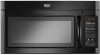
... examples in the vent system ■ using recirculation installation. diameter round vent C. Elbow (for use when figuring vent length. For optimal venting installation, we recommend: ■ using roof or wall caps that have back draft dampers ■ using a rigid metal vent ■ using the most direct route by minimizing the length of the vent and number of elbows to provide efficient performance ■ using uniformly sized vents ■ using duct tape to...
... examples in the vent system ■ using recirculation installation. diameter round vent C. Elbow (for use when figuring vent length. For optimal venting installation, we recommend: ■ using roof or wall caps that have back draft dampers ■ using a rigid metal vent ■ using the most direct route by minimizing the length of the vent and number of elbows to provide efficient performance ■ using uniformly sized vents ■ using duct tape to...

Installation Instructions
Page 12
... available replacement parts. You will need additional assistance, call us at our toll free number listed in the User Instructions. To calculate the length of vent. Two 90° elbows = 20 ft (6.1 m) B. 1 wall cap = 40 ft (12.2 m) C. 1 rectangular to round transition piece = 5 ft (1.5 m) D. 2 ft (0.6 m) + 6 ft (1.8 m) straight = 8 ft (2.4 m) If the existing vent is located behind the door. ■ Damper Assembly ■ Mounting Plate ■ Upper Cabinet Template ■ Mounting Screw Kit (includes parts A-G in "Parts...
... available replacement parts. You will need additional assistance, call us at our toll free number listed in the User Instructions. To calculate the length of vent. Two 90° elbows = 20 ft (6.1 m) B. 1 wall cap = 40 ft (12.2 m) C. 1 rectangular to round transition piece = 5 ft (1.5 m) D. 2 ft (0.6 m) + 6 ft (1.8 m) straight = 8 ft (2.4 m) If the existing vent is located behind the door. ■ Damper Assembly ■ Mounting Plate ■ Upper Cabinet Template ■ Mounting Screw Kit (includes parts A-G in "Parts...

Warranty Information
Page 1
... ®/™ ©2012. Any food loss due to repair or replace appliance light bulbs or filters. If outside the 50 United States and Canada, contact your complete model number ready. Expenses for travel and transportation for future reference. LIMITATION OF REMEDIES; ITEMS EXCLUDED FROM WARRANTY This limited warranty does not cover: 1. WARRANTY MAYTAG® MICROWAVE-RANGE HOOD COMBINATION LIMITED WARRANTY FIRST YEAR LIMITED WARRANTY (PARTS AND LABOR) For one year...
... ®/™ ©2012. Any food loss due to repair or replace appliance light bulbs or filters. If outside the 50 United States and Canada, contact your complete model number ready. Expenses for travel and transportation for future reference. LIMITATION OF REMEDIES; ITEMS EXCLUDED FROM WARRANTY This limited warranty does not cover: 1. WARRANTY MAYTAG® MICROWAVE-RANGE HOOD COMBINATION LIMITED WARRANTY FIRST YEAR LIMITED WARRANTY (PARTS AND LABOR) For one year...

Use & Care Guide
Page 1
... tell you still need your model and serial number located on your appliance. for additional information. SAVE THESE INSTRUCTIONS W10542862A WARNING You can be grounded. IMPORTANT SAFETY INSTRUCTIONS When using the microwave oven. ■ Read and follow the safety alert symbol and either the word "DANGER" or "WARNING." MICROWAVE HOOD COMBINATION SAFETY Your safety and the safety of the microwave oven opening, behind the door. If you...
... tell you still need your model and serial number located on your appliance. for additional information. SAVE THESE INSTRUCTIONS W10542862A WARNING You can be grounded. IMPORTANT SAFETY INSTRUCTIONS When using the microwave oven. ■ Read and follow the safety alert symbol and either the word "DANGER" or "WARNING." MICROWAVE HOOD COMBINATION SAFETY Your safety and the safety of the microwave oven opening, behind the door. If you...

Use & Care Guide
Page 2
... is not working properly, or if it is specifically designed to heat, cook, or dry food. Remove wire twist-ties from the microwave oven is not designed for industrial or laboratory use the cavity for example, near a kitchen sink, in a wet basement, near water - for storage purposes. IMPORTANT SAFETY INSTRUCTIONS ■ Use the microwave oven only for examination, repair, or adjustment. ■ Do not cover or block...
... is not working properly, or if it is specifically designed to heat, cook, or dry food. Remove wire twist-ties from the microwave oven is not designed for industrial or laboratory use the cavity for example, near a kitchen sink, in a wet basement, near water - for storage purposes. IMPORTANT SAFETY INSTRUCTIONS ■ Use the microwave oven only for examination, repair, or adjustment. ■ Do not cover or block...

Use & Care Guide
Page 3
.... SAVE THESE INSTRUCTIONS This device complies with A.M. Light Timer Set the cooktop light to set the Light On Time and Light Off Time in the display. Filter Reset Reset the filter status after 2-level cooking. Do not use an extension cord. Control Lock Activate to unlock control. Repeat to avoid unintended start. Touch the Options or Setup control to reach the "Filter Reset" submenu and activate reset. Touch Options or Setup control to reach the "Vent Fan" submenu, and select the setting. Touch the Start control to turn tones off...
.... SAVE THESE INSTRUCTIONS This device complies with A.M. Light Timer Set the cooktop light to set the Light On Time and Light Off Time in the display. Filter Reset Reset the filter status after 2-level cooking. Do not use an extension cord. Control Lock Activate to unlock control. Repeat to avoid unintended start. Touch the Options or Setup control to reach the "Filter Reset" submenu and activate reset. Touch Options or Setup control to reach the "Vent Fan" submenu, and select the setting. Touch the Start control to turn tones off...

Use & Care Guide
Page 4
... be changed . Slide the filter away from food as it out, and remove filter. The charcoal filter cannot be cleaned, and should be kept warm in the microwave oven. Opening the door during Keep Warm will be 100%, but may be programmed to 90), then touch the Start control. Enter the additional time, if desired, and start the microwave oven. Replace bulb, close bulb cover, and secure with screws. Manual Cooking/Stage Cooking Keep Warm Touch COOK TIME, touch number pads to enter time, touch COOK POWER...
... be changed . Slide the filter away from food as it out, and remove filter. The charcoal filter cannot be cleaned, and should be kept warm in the microwave oven. Opening the door during Keep Warm will be 100%, but may be programmed to 90), then touch the Start control. Enter the additional time, if desired, and start the microwave oven. Replace bulb, close bulb cover, and secure with screws. Manual Cooking/Stage Cooking Keep Warm Touch COOK TIME, touch number pads to enter time, touch COOK POWER...

Use & Care Guide
Page 5
...; Grease filters ■ Charcoal filter ■ Cooktop light bulb ■ Cavity light bulb ■ Heavy Duty Degreaser ■ affresh® Kitchen Appliance Cleaner ■ affresh® Stainless Steel Cleaner ■ affresh® Stainless Steel Wipes PROBLEM SOLVER Scan the code at 100% cooking power. If you avoid a service call. Firmly close the door, then start the cycle. ■ Control - Make sure Demo Mode (on cavity walls, microwave inlet cover, cooking rack supports, and area where the door touches...
...; Grease filters ■ Charcoal filter ■ Cooktop light bulb ■ Cavity light bulb ■ Heavy Duty Degreaser ■ affresh® Kitchen Appliance Cleaner ■ affresh® Stainless Steel Cleaner ■ affresh® Stainless Steel Wipes PROBLEM SOLVER Scan the code at 100% cooking power. If you avoid a service call. Firmly close the door, then start the cycle. ■ Control - Make sure Demo Mode (on cavity walls, microwave inlet cover, cooking rack supports, and area where the door touches...

Use & Care Guide
Page 6
... WARRANTY This limited warranty does not cover: 1. Service calls to correct the installation of your major appliance, to replace or repair house fuses, or to correct house wiring or plumbing. 2. Any food loss due to repair or replace appliance light bulbs or filters. Costs associated with the removal from your home of your major appliance is used in a manner that is contrary to published user or operator instructions and/or installation instructions...
... WARRANTY This limited warranty does not cover: 1. Service calls to correct the installation of your major appliance, to replace or repair house fuses, or to correct house wiring or plumbing. 2. Any food loss due to repair or replace appliance light bulbs or filters. Costs associated with the removal from your home of your major appliance is used in a manner that is contrary to published user or operator instructions and/or installation instructions...


